Table of Contents
Advertisement
Advertisement
Table of Contents

Related Manuals for SAMES KREMLIN Cyclomix Evo


Summary of Contents for SAMES KREMLIN Cyclomix Evo
- Page 1 ® Cyclomix Instruction manual DRT582165110 A - 2023/03...
- Page 2 No part of this document may be communicated or reproduced in any form, nor may its contents be used or communicated, without the express written permission of Sames. The descriptions and characteristics contained in this document are subject to change without notice. ©...
- Page 3 Services Certification and referencing Sames is certified as a training centre by the DIRRECTE of the Auvergne Rhône Alpes region under the number 84 38 06768 38. Throughout the year, our company provides training courses that enable you to acquire the know-how required for the implementation and maintenance of your equipment in order to guarantee its long-term performance.
-
Page 4: Table Of Contents
Cyclomix® Evo 1. Health and safety instructions - - - - - - - - - - - - - - - - - - - - - - - - - - - - - - - - - - - - 7 1.1. - Page 5 2.5.10............Use the Batch function 70 2.5.11.
- Page 6 5.2.15. 3K gun overview complete option ..........123 5.2.16.
-
Page 7: Health And Safety Instructions
1. Health and safety instructions 1.1. Configuration of the certified equipment This manual defines the configuration of the certified equipment. 1.2. Marking 1.2.1. Marking of ATEX and non-ATEX boxes Each device is marked with the name of the manufacturer, the reference of the device and the important information for the use of the device: air pressure, electrical power. - Page 8 1.2.1.1. Marking main box - ATEX nameplate The main box is not an ATEX box. It is an associated box that can be connected to an ATEX board installed in an ATEX zone. There are therefore ATEX and non-ATEX versions. Description Sames Code Manufacturer's brand...
- Page 9 1.2.1.2. Marking of main box - non ATEX nameplate The main box is not an ATEX box. It is an associated box that can be connected to an ATEX board installed in an ATEX zone. There are therefore ATEX and non-ATEX versions. Description Sames Code Manufacturer's brand...
- Page 10 1.2.1.3. Additional box Evo+ marking - ATEX nameplate The additional box Evo+ is not an ATEX box. It is an associated box that can be connected to an ATEX board installed in an ATEX zone. There are therefore ATEX and non-ATEX versions. Description Sames Code Manufacturer's brand...
- Page 11 1.2.1.4. Additional box Evo+ marking - non ATEX nameplate The additional box Evo+ is not an ATEX box. It is an associated box that can be connected to an ATEX board installed in an ATEX zone. There are therefore ATEX and non-ATEX versions. Description Sames Code Manufacturer's brand...
- Page 12 1.2.1.5. Marking remote box - non ATEX nameplate Description Sames Code Manufacturer's brand STAINS FRANCE Place of production of the equipment. Product name ® Cyclomix Evo box CE: European conformity II (2) G : Use in explosive areas II: Group II (2): Category 2 Surface equipment intended for use in environments where explosive atmospheres due to gases, vapors, mists are likely to occur occasionally during normal operation.
-
Page 13: Standards And Guidelines Applied
1.2.2. Standards and guidelines applied European Standards and Directives - EU UK Standards and Guidelines - UKCA • 2006/42/CE Machinery • 2008 No. 1597 The Supply of Machinery (Safety) • / Partly completed machinery. Regulations 2008 • 2014/34/UE Potentially Explosive •... -
Page 14: Glossary
1.2.3. Glossary Base Component A Catalyst Component B, may also be referred to as hardener. Thinner Component C Product ratio For a product made of 2 components, a base (A) and a catalyst (B) are used. The ratio R corresponds to the ratio B / A. If R = 10% it will be necessary that the mixture consists of 10 volumes of B for 100 volumes of A. -
Page 15: Meaning Of The Pictograms
1.3. Meaning of the pictograms Electrical Hazard Danger Danger Hot parts Danger General Automatic start or hot surfaces Risk of explosion Danger Danger Danger Pinching Danger Danger Danger High pressure and/or crushing Atex Area Risks Corrosive products of flammability Danger Danger Prohibition Obligation... -
Page 16: Precautions For Use
1.4. Precautions for use 1.4.1. Safety of persons Technical manuals, labels Before putting the equipment into operation, read carefully: • All operating instructions, • The labels on the equipment before putting the equipment into operation. Training Personnel using this equipment must be trained in its use. Points of vigilance: instructions, safety. - Page 17 Qualification of the staff ® Interventions on the Cyclomix Evo must only be carried out in accordance with the rules and regulations in force, by trained and qualified personnel. The following conditions must be met: • The personnel must have special skills and experience in the relevant technical field. This applies in particular ®...
- Page 18 Sames declines all responsibility in case of:: • Physical or psychological injuries. • Direct or indirect material damage due to the use of chemical substances. • Recommendations and responsibilities of the operator of the Cyclomix® Evo on the use of the applied products. •...
-
Page 19: Integrity Of The Equipment
1.4.2. Integrity of the equipment • Engine cover. • Coupling protector. • Carters. Protection device Protectors allow safe use of the equipment. 1.5. Warnings It is imperative that anyone with a pacemaker not use the equipment or enter the projection area. -
Page 20: Installation Rules
1.5.1. Installation rules The installation of any system that does not comply with the rules specified below is strictly prohibited. Environment Environmental risks must be controlled in the following manner: • Have a qualified electrician check for ground continuity. If ground continuity is not assured, check the terminal, wire and grounding point. -
Page 21: Important Recommendations
1.6. Important recommendations 1.6.1. Limits of use and/or improper use Any use other than that described in this document and the operating instructions, as well as any use beyond that, is considered improper. The manufacturer accepts no liability for any resulting damage. The user bears the sole risk. The following points describe incorrect or prohibited use: •... -
Page 22: Safety Recommendations During Maintenance
Equipment generalities It is prohibited to: • Carrying products that do not meet specifications. ® • Use, maintenance, repair, installation or commissioning of the Cyclomix Evo by unauthorized, untrained personnel or by a private user. ® • Use the Cyclomix Evo without grounding. -
Page 23: Check The Delivered Items
1.6.4. Check the delivered items ® • Remove the Cyclomix Evo from its packaging. • Dispose of packaging properly. Comply with your local regulations.. ® • Check that the Cyclomix Evo has not been damaged during transport. • Immediately notify the carrier and Sames in writing of transportation damage. ®... -
Page 24: Warranty
1.7. Warranty Sames provides a contractual warranty for a period of twelve (12) months from the date of delivery to the to the customer, provided that the conditions of use indicated in this technical manual are respected. In order to be implemented, the warranty request must precisely define in writing the malfunction in question, must be accompanied by the defective material and/or component and must be informed of the conditions of the equip- ment purchased by the customer from Sames. -
Page 25: Description
2. Description 2.1. Generalities ® 2.1.1. Property of the Cyclomix ® The Cyclomix Evois designed to: • Mixing and dosing up to 3 products, • Supply of 1 or 2 guns by managing independently the Potlife (product life time), the rise in color and the flushing of each circuit. -
Page 26: Function Of The Different Components
2.2. Function of the different components Component Function ® Cyclomix Evo 2K A 2K dosing system is a system that mixes two liquid components (usually bases and hardeners) in a precise ratio to form a solid film. 2K dosing systems can be manual or automatic. 2K dosing systems are often used for applications that require high precision in dosing and mixing of components to ensure the quality of the final product. - Page 27 Component Function Air regulation An air control box is used to regulate and control the spray air pressure of the gun. air pressure of the spray gun. The box also allows the spray air to be cut off during the priming and flushing phases. Flushbox gun The gun flushing box has the following function •...
-
Page 28: Cyclomix® Evo Presentation - 2K Configuration
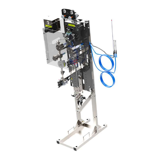
® 2.2.1. Cyclomix Evo presentation - 2K configuration Control kit for 2 regulators Spray air control module 2K injection block assembly Flowmeter assembly Manometer assembly 0-6 Bar Regulator Assembly T-filter Static mixer Color changer module 2-gun block management ® 2.2.2. Cyclomix Evo presentation - 3K configuration 3K injection block assembly Mass flowmeter assembly... -
Page 29: Presentation Of The Main Box
2.2.3. Presentation of the main box 2.2.3.1. Exterior of the box 8 EV BLOCK ASSEMBLY WITH T-FITTING 2 POSITION SWITCH 8 EV BLOCK ASSEMBLY WITH ANGLE FITTING 2.2.4. Présentation of the main box 2.2.4.1. Inside the box TRAVERSE JUNCTION BLOCK 24V INTERFACE RELAY ZDK 1.5 MM²... -
Page 30: Presentation Of The Additional Box Evo
2.2.5. Presentation of the additional box EVO+ 2.2.5.1. Exterior of the box LOCK CABLE GLAND CORDON CABLE 2.2.6. Presentation of the additional box EVO+ 2.2.6.1. Inside the box DIOB CARD SET SET OF SQUARE DIOB CARD AND RJ45 CABLE LG 5M SET X6 SET X3 PROPORTIONNALS VALVES INTRINSEQUES BARRIERS... -
Page 31: Presentation Of The Remote Box
2.2.7. Presentation of the remote box 2.2.7.1. Exterior of the box CABLE GLAND 2.3. Presentation of the remote box 2.3.1. Inside the box NIOB CARD KIT WITH CABLE CARD TERMINAL BLOCKS Member of Exel group DRT582165110 A - 2023/03... -
Page 32: Presentation Of The Electronic Cards
2.3.2. Presentation of the electronic cards 2.3.2.1. Presentation of the CCB card The CCB (Common Control Board) is the motherboard. The CCB board manages the machine process and collects information from the daughter boards. LED description LED status Description When ON it signals that the main chip is running. red LED •... - Page 33 LED status Description LED RUN - When ON or blinking it indicates the EtherCAT chip is not running • User should check that both switches (cf. 6) are set to OFF and reboot the orange LED cabinet. Position of the connectors Description Connector to robot board Boot jumpers...
- Page 34 Screen jumpers visualization Position of the display cables and Ethernet cables Boot jumpers Member of Exel group DRT582165110 A - 2023/03...
- Page 35 2.3.2.2. Presentation of the ANAB card The ANAB (Analog Board) is a daughter board, it allows the control of analog device (proportional valve…) and the reading of analog value (temperature sensor, pressure sensor…). LED description LED status Description When ON it signals that the program is running. red LED It blinks when 3 times slowly during the board boot.
- Page 36 LED status Description This LED indicates the status of the EtherCAT network. Extract from the documentation ETG.1300 S (R) V1.1.1 When it is green (see below) Indicator states Slave state Description Initialization The device is in the INIT state. The device is in Blinking Pre-operational pre-operational state...
- Page 37 Position of connectors Description Main chip reset button EtherCAT switches. EtherCAT chip (netx90) reset button EtherCAT input port (port 0, on the left) Power connector (24V) Member of Exel group DRT582165110 A - 2023/03...
- Page 38 The NIOB (New Input Output Board) is a board with 10 digital inputs (24V) and 10 digital outputs (24V). On the Cyclomix Evo the board can be found in the deported cabinet. It is used to capture the input signal received when the user select a button (using the magnet).
- Page 39 LED status Description OUT8 (green) OUT8 is driven to 24V OUT9 (green) OUT9 is driven to 24V OUT10 (green) OUT10 is driven to 24V IN1 (green) IN1 is driven to 24V IN2 (green) IN2 is driven to 24V IN3 (green) IN3 is driven to 24V IN4 (green) IN4 is driven to 24V...
- Page 40 2.3.2.4. Presentation of the DIOB card The DIOB (Digital Input Output Board) is a daughter board. The DIOB card can drive up to 32 outputs and read 10 digital inputs. The DIOB card is used to read data from flowmeter and control elecrovalves. Member of Exel group DRT582165110 A - 2023/03...
- Page 41 LED status Description When ON it signals that the program is running. red LED It blinks when 3 times slowly during the board boot. It blinks fast during the board identification (cf. Identify in Maintenance on CCB). This LED indicates the state of the EtherCAT chip. When ON it signals that the chip LED RUN (green) is operational to run.
- Page 42 Position of the connectors Connectors status Description Main chip reset button EtherCAT switches EtherCAT chip (netx90) reset button EtherCAT input port Board switches: • All set to OFF for the main DIOB. • At least one set to ON for DIOB extension board (DIOB_T). Member of Exel group DRT582165110 A - 2023/03...
-
Page 43: Principle Of Designation And Codification
2.4. Principle of designation and codification ® A Cyclomix Evo is made up of a product board and a control box that allows all the elements on the product board to be controlled. These 2 elements constitute a set with a commercial reference and which is described by a significant designation. ®... - Page 44 Component blocks (Comp. A / Comp. B / Comp. C) The ''component'' blocks are composed of 6 characters: • The first 2 characters concern the number of products that can be connected to this component (products and solvents included). • The 3 character indicates the presence or not of a filter on the component.
- Page 45 Injection and mixing block The block ''injection and mixture'' is composed of 8 characters: • The first character indicates the size of the product B injector. • The second character indicates the type of injection valve for product B. • The third character indicates the size of the product injector C. •...
- Page 46 Painting circuit block ® The paint circuit block allows you to define the characteristics of the circuit(s) downstream of the Cyclomix Evo. • The first character is used to define the number of circuits (gun). • The second character is used to define the number and type of fast purge valve. •...
- Page 47 Control box block The last block is for information about the control box. • The first character identifies the type of communication present in the box and allowing to communicate with another equipment. • The second character indicates the number of flowmeters present in the box. These flowmeters, connected to the gun's atomization air, allow the Cyclomix®...
- Page 48 Number of Type of Number of Distribution of the Number of Directive Type of flowmeters gun(s) communication I/O cards blocks solenoid valves debistats Without 1 card Module 2 Gear Aucun 1 gun 10100000 communication (11 products) 1 & 3 flowmeters débistat 2 cards Module...
-
Page 49: Commercial Designation Principle Of The Cyclomix® Evo
® 2.4.2. Commercial designation principle of the Cyclomix Evo. The commercial designation of a Cyclomix® Evo does not allow for a complete definition of the dosing unit, but it does allow you to know the main characteristics.Example of codification for a 2 component machine: ®... - Page 50 • The fifth set, sixth and seventh in the case of a Cyclomix® Evo 3 components, allowing to identify the configuration of each component. This includes the number of color changers, the presence or absence of a filter and the type of flow meter. The first letter of this set indicates the component.
- Page 51 • The seventh group indicates the type and position of the flow meters that can be connected to the panel. • The eighth and last group indicates the number of flow meters present in the cabinet. Example of configuration: • Coffret Evo CE 2G ET 6P X R GGX 2F Number Number of Type of...
-
Page 52: Human/Machine Interface And Operation
2.5. Human/Machine Interface and operation 2.5.1. Cutting into 6 worlds The home screen offers 6 basic features. • Production menu: set of screens used during the production phases. • Recipes menu: set of screens allowing the setting of the different recipes. •... -
Page 53: Configuring The Cyclomix® Evo - General Settings
® 2.5.2. Configuring the Cyclomix Evo - General settings ® The Configuration mode technically defines the Cyclomix Evo according to the user's choices. Access to the Configuration mode according to the screens below. Information Explications provided Traceability of information and identity of the equipment in the user's language. These parameters must be filled in for the first start-up. - Page 54 Information Explanations Example(s) of screen(s) provided The user has the choice of the following units: Data Choice 1 Choice 2 Pressure Temperature °C °F Volume cc/liter/ oz/gallons & Length /inches Depending on the screens and fields, the units displayed will be the following: Data Choice 1 Choice 2...
- Page 55 Information Explanations Example(s) of screen(s) provided • Allows you to define if the Cyclomix® Evo will prepare mono and bi-component products (choice = 2K) or mono, two or three component products (choice = 3K). • Si If 2K, then a certain number of parameters present in the configuration or confi- guration or recipe screens will be grayed out or absent.
- Page 56 Information Explanations Example(s) of screen(s) provided • The FLUSHBOX positions the gun so that the rising and flushing phases occur automatically without the user having to pull the FLUSHBOX gun trigger. • The user uses this FLUSHBOX (check box) during the priming and flushing phases. •...
- Page 57 Information Explanations Example(s) of screen(s) provided • Define the management of the product pressure inside the Cyclomix® Evo. Pressure regulator • This option corresponds to the addition of pressure regulators positioned between the product feed color changers and the flow meters.
- Page 58 Information Explanations Example(s) of screen(s) provided • This parameter defines a time of This parameter defines a time for not monitoring the paint flow while the gun is open. This avoids an error due to the debistat detecting a gun ope- ning when the gun opening while the flowme- Gun trigger time ters are not running.
-
Page 59: Calibrate A Product
2.5.3. Calibrate a product In order to allow a good dosage of the Test valve B different products, it is imperative that the volumes measured by the flowmeters are very precise. Depending on the viscosity, the volume per pulse may vary slightly, so it is necessary to calibrate each product. - Page 60 For each phase, follow the instructions on the screen: Priming phase Calibration phase ® During the calibration phase, the Cyclomix Evo will flow approximately 1000 pulses of product. This means, for example, that with a 0.24cc flow meter, the volume obtained will be 240cc. This product must be delivered in a container in order to measure this volume.
-
Page 61: Manage Recipes
Circuit flushing phase The flushing phase is imperative before leaving the calibration mode. It will not be possible to leave the calibration mode without having performed a flushing. 2.5.4. Manage recipes A recipe includes information about the dosage and mixing of products A, B and C in the case of a 3 component mixture. - Page 62 2.5.4.1. Edit a recipe The access to a recipe is done from the main menu and by selecting the Recipes icon. When several recipes have been declared, horizontal arrows allow you to navigate from one recipe to another. If page 2 of a recipe is displayed then pressing the horizontal arrow will also access page 2 of the new recipe. This allows you to quickly compare the information between each recipe.
- Page 63 It happens that on the technical data sheets of the products the ratio is declared in shares. By pressing the button ''Parts'', it is possible to enter this information directly via a specific screen. To define by yourself the injection frequency, uncheck the box ''Autonomous injection'' to allow access to the configuration page.
-
Page 64: Put In Product
Pressing this button opens the following screen: • The New recipe button allows you to create a new recipe. You will have to fill in all the parameters. • To simplify the creation of a recipe, it is possible to duplicate an existing recipe and have only a few parameters to modify. -
Page 65: Priming
2.5.6. Priming The priming is the phase that consists in filling the supply circuits of the sprayers with mixed paint ready to be applied. Ready to apply means at the right ratio and the right mix. ® The priming phase is managed automatically by Cyclomix Evo. -
Page 66: Production Flushing
2.5.7. Production flushing The production flushing is a flushing phase that can be configured for each recipe. This flushing phase consists of a number of configurable steps. Up to 20 flushing steps can be configured per recipe. Each flushing step will be defined by a strategy and parameters inherent to each strategy. The production flushing can be started in 2 ways: •... - Page 67 The circuit 2 or 3 possible choices depending on the configuration: • Machine and mixer. • Gun hose 1. • Gun hose 2. If... Then... Therefore, this flushing step will be systematically performed If the circuit is defined as Machine and regardless of the gun(s) used during the production phase.
- Page 68 The product ® The Cyclomix Evo allows the selection of all connected products. It is therefore possible to choose a product connected to the A, B or C color changer, whether this product is a solvent, a color or a catalyst. Volume or time It is possible to choose a volume of product to be circulated or to define a time during which the product valve will remain open.
-
Page 69: Machine Flushing
2.5.8. Machine flushing The machine flushing is a rinsing phase that can be set from the configuration menu, this flushing will be identical whatever the recipe used. Like the production flushing, this flushing consists of a number of configurable steps. Up to 4 flushing steps can be configured. -
Page 70: Use The Batch Function
2.5.10. Use the Batch function Test valve B Test valve A In order to allow a good dosage of the various products, it is imperative that the volumes measured by the flowmeters are very precise. It is therefore necessary to be able to regularly check the accuracy of the flowmeters. -
Page 71: Manage Users
Priming phase Sampling phase In order to start a sampling, it is necessary to have previously indicated the total volume of paint desired. If this is not the case, an alarm message appears on the screen and the function will not start. This volume corresponds to the total volume desired, depending on the ratio of the selected recipe the expected volumes of each product are displayed. - Page 72 On this screen, it is possible either to disconnect the current user or to connect a new user. To do this, enter the user name and the associated password. If the user has a ''personalized'' profile then after validation of his information the menu screen will appear and the menus where the user cannot access will be grayed out.
- Page 73 ® The default user is the user who will be automatically connected when the Cyclomix Evo is started or when another user is disconnected. When the custom profile is defined then an Access Rights button appears at the bottom of the screen. This Access Rights button takes you to a new screen to define specific user rights.
-
Page 74: Manage Consumption
2.5.12. Manage consumption ® The Cyclomix Evo records the volumes of all products flowing through the flowmeters. All volumes are divided into 3 categories: volumes by product, volumes by recipe and volumes by lot number. The access to the consumptions is done from the main menu. When opening this menu, the interface displays the consumption volumes by recipe. -
Page 75: Exploiting The Production Screens
2.5.13. Exploiting the Production screens Putting a recipe into production 2.5.13.1. The production of a recipe is very intuitive and is done very quickly from the touch screen. Then it is necessary to select the desired recipe by pressing the corresponding button.. - Page 76 If the machine is equipped with a 2-gun module, then following the selection of the recipe it will be necessary to select the gun or guns that will be used. If both guns are selected then the priming will be done on both circuits starting with circuit 1 and if not the priming will be done only on the selected circuit.
-
Page 77: Paint Optimization Function
2.5.13.2. Production screen The production screen contains a number of production-related information. Reference points Designation Indicates the name of the current recipe Bar graph indicating the evolution of the Potlife per gun Indicates the ratio requested in the recipe Indicates the actual ratio during production Indicates the total flow delivered by the machine Indicates the Potlife count per gun Indicates pressure and temperature information - value mentioned in the recipe on... -
Page 78: Zoom Function On Ratio And Flow Rate
2.5.15. Zoom function on ratio and flow rate ® The Cyclomix Evo allows you to zoom in on the actual ratio or the current flow rate while being a few meters away from the cabinet. To do this, simply press the value you wish to display. 2.5.16. -
Page 79: Register A Batch Number
By selecting the box on the right, a keyboard appears allowing you to enter the new desired ratio. When a ratio correction is requested then the target ratio displayed on the production page is in orange. 2.5.17. Register a batch number In order to have a traceability on the painted parts: •... -
Page 80: Mobile Application
2.6. Mobile application The H.M.I. system is also deployed in mobile application mode. Member of Exel group DRT582165110 A - 2023/03... -
Page 81: Technical Features
3. Technical features ® 3.1. Technical features of the Cyclomix Type of machine 2K, 3K & (1K) Type of paint Water or solvent based, acid catalyst, PU, Epoxy Number of product A Number of product B Number of product C Number of recipes Ratio 100:1 to 1:2 (1% to 200%) -
Page 82: Dimensions (Cm)
3.2. Dimensions (cm) ® 3.2.1. Dimensions Cyclomix Member of Exel group DRT582165110 A - 2023/03... -
Page 83: Main Box Dimensions
3.2.2. Main box dimensions Member of Exel group DRT582165110 A - 2023/03... -
Page 84: Additional Box Evo+ Dimensions
3.2.3. Additional box Evo+ dimensions 3.2.4. Remote box dimensions Member of Exel group DRT582165110 A - 2023/03... -
Page 85: Operating Principle
3.3. Operating principle 3.3.1. File and communicate in network mode Introduction This section contains the information necessary to easily use the optional communication module to display and ® control the Cyclomix Evo via a network link. Description ® In auto mode (network), a PLC manages the display of data and/or the control of data from the Cyclomix Evo. - Page 86 Features IP Ethernet Module Front view of the RJ45 module Network status port 2 yellow (4B) Network status port 2 green (4A) Network status port 1 yellow (3B) Network status port 1 green (3A) Module status red (2B) Module status green (2A) Module status red (1B) Module status green (1A) The Ethernet cable can be connected to both ports.
- Page 87 LED module status LED status Description No power Controlled by a working scanner and, if CIP Sync is enabled, the time is synchronized with a Grand- Green master clock. Not configured, Scanner in standby state, or, if CIP Sync is enabled, the time is synchronized with the Green, flashing Grandmaster clock.
- Page 88 Profinet module Front view of the RJ45 module Network status port 2 yellow (4B) Network status port 2 green (4A) Network status port 1 yellow (3B) Network status port 1 green (3A) Module status red (2B) Module status green (2A) Network status red (1B) Network status green (1A) The Ethernet cable can be connected to both ports.
- Page 89 LED network status LED status Description Comments • No power Offline No connection to the I/O controller • • Connection with the I/O controller established Green Online (OPERATION) • Input/Output controller in working order • Connection with the I/O controller established •...
- Page 90 Profinet parameters The module must receive a station name and an IP address in order to participate in PROFINET. ® These parameters can be set on page 17 of the Configuration menu on the Cyclomix Evo. Profinet On PROFINET, the characteristics of a device are stored in an XML data file. This file, called "GSD", is used by the PROFINET engineering tools when setting up the network configuration.
- Page 91 CC-linkModule Front view of the CC-link module Not used Not used Not used Not used Module status red (2B) [Operating LED] Module status green (2A) [Operating LED] network status red (1B) [Error LED] LED CC-link Operating LED LED status Indication / Description No participation in the network, shutdown state (no power) Green Participant, normal operation..
- Page 92 Error LED LED status Description No error detected (no power) Major defect (Exception or FATAL event) Red, flickering CRC error (temporary flickering) Red, flashing Station number or baud rate has changed since startup (flashing) CC-Link connector LED status Description Comments RS485 RxD/TxD Positive RS485 RxD/TxD Négative Signal mass...
- Page 93 Modbus module Front view of the RJ45 module Network status port 2 yellow (4B) Network status port 2 green (4A) Network status port 1 yellow (3B) Network status port 1 green (3A) Module status red (2B) Module status green (2A) Network status red (1B) Network status green (1A) The Ethernet cable can be connected to both ports.
- Page 94 Module status LED LED status Description No power Green Normal operation Major fault (including Anybus exception), FATAL Red, flashing Minor defect Alternance rouge/vert Firmware update from the current file system LED de liaison/activité 3/4 LED status Description No link, no activity Green Link (100 Mbit/s) established Green, flashing...
- Page 95 Data exchange Exchanging data flags for CC-Link only. The location of the system area is at the very end of the bit area. 16 bits are reserved for this use. Description Description (Reserved) (Reserved) Normal operation if high (for initial set- ting, at the rising edge of the PLC «Ini- tial Data Processing complete»...
- Page 96 ® From the PLC to the Cyclomix Evo module ® 2 words are exchanged from PLC to the Cyclomix Evo. Label Parameter description PLC_Command_1 Commands requested by the PLC (see description hereafter) PLC_Command_2 Commands requested by the PLC (see description hereafter) PLC_Command_1 Détail de la commande PLC mot 0 en bit Push color gun 2...
- Page 97 ® 25 words are exchanged from Cyclomix Evo to PLC. Label Parameter description Unit Flag_1 Status information 1 (see description hereafter) Flag_2 Status information 2 (see description hereafter) 11 = Stop production, 12 = Prime ongoing, 13 = Production, 14 = Production flush ongoing, 15 = Machine flush ongoing, 16 = Regeneration État de la machine ongoing,...
- Page 98 Flag_1 Detail of status 1 information word 0 in bit ® Machine flush ongoing The Cyclomix Evo is in machine flush Potlife alarm gun 2 The potlife time has been reached on gun 2 Potlife alarm gun 1 The potlife time has been reached on gun 1 Error Presence of a fault Idle potlife...
- Page 99 set, when the robot should open its gun only the Gun x in use will be set. Faults_1 Detail of fault 1 information word 17 in bit Low flow alarm The minimum flow rate has been reached High flow alarm The maximum flow rate has been reached Ratio deviation The average ratio has been outside the limits.
- Page 100 Data mapping for Modbus only Write/Read Address Description Type Size Unité 30002 Machine state 16 bits unsigned word 30003 Production flow 16 bits cc * 10/min unsigned word 30004 Ratio A/B 16 bits ratio * 100 unsigned word 30005 Current recipe 16 bits unsigned word unsigned...
-
Page 101: Schematics
4. Schematics 4.1. Fluid schematics Not applicable. 4.2. Electrical schematic 4.2.1. Main box Member of Exel group DRT582165110 A - 2023/03... -
Page 102: Network Overview
4.2.2. Network overview 4.3. Additional box EVO+ 4.3.1. Implantation Member of Exel group DRT582165110 A - 2023/03... - Page 103 Member of Exel group DRT582165110 A - 2023/03...
-
Page 104: Network Overview
4.3.2. Network overview Member of Exel group DRT582165110 A - 2023/03... -
Page 105: Remote Box
4.4. Remote box 4.4.1. Implantation 4.4.2. Network overview Member of Exel group DRT582165110 A - 2023/03... -
Page 106: Installation Of Boxes
4.4.3. Installation of boxes Member of Exel group DRT582165110 A - 2023/03... -
Page 107: Start-Up
5. Start-up 5.1. Tools Tools and accessories required: The tools listed below are recommended for installation and maintenance of the equipment. • A cross-headed screwdriver. • A flat screwdriver (small, medium, large). • A 17 mm flat wrench. • An Allen key (2,5 mm; 4 mm; 5 mm; 10 mm). •... -
Page 108: Installation
5.2. Installation Note: The equipments are tested in air and water to check the correct operation and the tightness of all components. For installation rules: see § 1.5.1 page 20 5.2.1. Configuration of the product part in and out of the cabin Inside the cabin Area1 Outside the... -
Page 109: Install The Feet When Unpacking The Cyclomix® Evo With Frame
® 5.2.2. Install the feet when unpacking the Cyclomix Evo with frame. Refer to the foot mounting sheet provided with the equipment or the procedure below. • Step 1: In the received packing box: ® • Identify the box (A) containing the Cyclomix 2 possible positions for the box containing the frame frame. - Page 110 • Step 2: ® On the Cyclomix Evo (horizontal position), visual A opposite, insert and slide to the stop the components of the foot as shown in visual B opposite. • Step 3: Take from the bag: screws and nuts. Fix by screwing and tightening the interlocking elements of the foot. •...
- Page 111 • Step 5: Once the elements have been tightened, 2 participants are tilted into a vertical position on a flat ® Cyclomix Evo floor. Member of Exel group DRT582165110 A - 2023/03...
-
Page 112: Electrical Connection
5.2.3. Electrical connection ® The Cyclomix Evo an be powered by 220V or 110V.. ® The electrical connection of the Cyclomix Evo must be made according to the wiring diagram on the N and L terminal blocks located inside the cabinet and provided for this purpose. A 3-wire cable (2 phases + ground) of 1.5mm²... -
Page 113: Air Supply To The Box
5.2.5. Air supply to the box The air supply of the box is done with a hose of diameter 8x10 at the level of the snap-in connection located under the box. If the box is not equipped with debistats (AIRLESS or automatic mode) then the supply will be made directly at item 3 of the picture below. -
Page 114: Location Of Cable Outlets In The Main Box
5.2.6. Location of cable outlets in the main box 5.2.7. Location of the additional box cable outlets Member of Exel group DRT582165110 A - 2023/03... -
Page 115: Equipotential Bonding Of The Main Box
5.2.8. Equipotential bonding of the main box 5.2.9. Equipotential bonding of the main box Member of Exel group DRT582165110 A - 2023/03... -
Page 116: Equipotential Bonding Of The Remote Box
5.2.10. Equipotential bonding of the remote box 5.2.11. Air supply to the product plate The air connection of the product plate is necessary to supply the electrovalve of the injection valve as well as the AIRCHOP valve. The air connection must therefore be made at the Y connection located on the side of the support plate as shown in the image below. -
Page 117: Air Supply To The Spray Box
5.2.12. Air supply to the spray box The spray box is used to supply or cut off the spray air that reaches the gun. The air consumption also allows the machine to know if the gun is open or closed thanks to the debistats located in the box. This means that this box must be fed from the outlet of the debistats on the box and then the air supply to the gun will be from this box. -
Page 118: Connection Of The Flowmeters
5.2.13. Connection of the flowmeters Gear flowmeters - Non ATEX version On the flowmeter side, the sensors are screwed in and locked with the locknut. The sensor must be screwed in order to be in contact with the flowmeter and then it is necessary to lock the locknut in order to avoid that the sensor unscrews in time. - Page 119 The flowmeter cables are connected to the 053X1 terminal block assembly. For the flowmeter of component A (base): • Wire 1 is connected to terminal block 1 • Wire 2 is connected to terminal block 7 • Wire 3 is connected to terminal block 4 For the flowmeter of component B (catalyst): •...
- Page 120 • The cable of the flowmeter A (base) is connected to the intrinsic barrier 053V1. • The cable of the flowmeter B (catalyst) is connected to the intrinsic barrier 053V2. • The cable of the flowmeter C (diluent) is connected to the intrinsic barrier 053V3. For each cable, wire 1 of the cable connects to terminal 1 of the barrier, wire 2 connects to terminal 3 and wire 3 connects to terminal 4.
- Page 121 The cable of the flowmeter A (base) is connected by screwing on the one hand to the FOP sensor and on the other hand to the fiber optic receiver RFO1. The cable of the flowmeter B (catalyst) is connected by screwing on the one hand to the FOP sensor and on the other hand to the fiber optic receiver RFO2.
-
Page 122: Gun Overview Complete Option
5.2.14. 2K gun overview complete option Member of Exel group DRT582165110 A - 2023/03... -
Page 123: Gun Overview Complete Option
5.2.15. 3K gun overview complete option Member of Exel group DRT582165110 A - 2023/03... -
Page 124: Connection Of The Mixing Block
5.2.16. Connection of the mixing block The 2K mixing block consists of 4 valves which are controlled from the main control panel. The 4 valves are: • The injection valve, • The sampling valve on the catalyst side, • The AIRCHOP valve, •... -
Page 125: Test Valves And Airchop Connections
5.2.18. Test valves and AIRCHOP connections The test valves A and B are controlled via the outputs n° 17 and n°18 on the DIOB 1 card and then the solenoid valves 3 and 4 of block n°3. The AIRCHOP valve is controlled via output 22 on the DIOB 1 card and then the solenoid valve 7 of block n°1. The connection between the valves and the solenoid control valves is made with a 4mm diameter pneumatic hose. - Page 126 Connection on the mixing block side Test B Test A AIRCHOP Connection on the cabinet side AIRCHOP Test A Test B Member of Exel group DRT582165110 A - 2023/03...
-
Page 127: Connection Of The Product Valves
5.2.19. Connection of the product valves As with the mixing block valves, the connection of the product valves is made with a 4 mm diameter hose. As the distribution of the products is configurable, the connection of the control hoses can only be carried out once the configuration of the products has been completed. -
Page 128: Connection Of An Electrostatic Box
The various elements must be connected to the solenoid valves according to the table below: Functions Block 1 Block 3 EV block number Position of the solenoid valve Number of product output Block 4 EV block number Position of the solenoid valve 5.2.21. -
Page 129: Waterproofing Tests
In this configuration, it is necessary to take the 220V downstream of the disconnecting switch of the box in order to avoid the maintenance of the power supply of the electrostatic box during a cut of the box. It will also be necessary to connect the neutral of the electrostatic box to the power supply terminal of the box. 5.2.22. - Page 130 Base circuit test • Step 1: Open the 2-gun block (activate the 2 outputs of the block). • Open the guns. • Fluid can flow out while the pressure drops and then it should stop. If this is not the case, then it means that a color changer is not waterproof. •...
-
Page 131: Compatibility - Hoses - Product -Pressure
Step 2: • Leave the 2-gun block open. • Open a valve on the color changer cata side. • A pressure build-up occurs between the color changer and the injection valve that can cause momentary pulses. • Opens the guns. •... -
Page 132: Maintenance
6. Maintenance Preventive maintenance is an inherent part of production and ensures the reliability of the installation. As a reminder, the performance of the equipment can only be guaranteed if a minimum of control and cleaning operations are performed on this equipment. Soling and wear of the equipment depends on the operating and application conditions as well as on the production rate. -
Page 133: Maintenance Summary Table
6.1. Maintenance summary table The frequency of maintenance indicated in the procedures below is only indicative. The user will have to create his own maintenance range as he uses the Sames equipment. Procedure Detail Duration Frequency Maintenance of the concerned sub-assembly screen filter - screen seals Replacement Remove the screen filter. -
Page 134: Maintenance Video
6.1.1. Maintenance video Please refer to the oline maintenance video on the product page. The assembly and disassembly operations are specified. 6.1.2. Additional maintenance Please refer to the following documentations: • 582.071.110-EN - 2105 COLOR CHANGERS ® • DRT7115 E - 2022/11 Nanogun+ Airmix - GNM 6080 LR- HR- MR Versions •... -
Page 135: Preventive Maintenance Plan - Pmp 582165110
6.2. Preventive Maintenance Plan - PMP 582165110 see § 9.1 page 146 The proposed preventive maintenance plan aims to define in an exhaustive way, the actions of checking, replacement and cleaning of the installed Sames equipment. In order to anticipate breakdowns and malfunctions that may be due to technical deviations of the installation, the preventive maintenance plan annexed to the user's manual recalls the routine maintenance operations necessary for a better comfort in the use of the production tool. -
Page 136: Servicing
6.3. Servicing These maintenance operations can be performed online. Before any intervention, refer to the health and safety instructions (see § 1.5 page 19). Member of Exel group DRT582165110 A - 2023/03... -
Page 137: Replacement
6.4. Replacement The following maintenance operations must be performed in the workshop. 6.4.1. Starting up the EtherCAT bus 6.4.1.1. Introduction The main network of the machine is the EtherCAT protocol. It is essential because it allows the inter-card communication and especially the control of the valves. Therefore, it is important to check that the recorded bus configuration is correct. - Page 138 • Step 2: Later, if the user needs a temperature sensor, he will have to add an analog card (ANAB). • After wiring this new card, the user will be able to restart his box. • At start-up, this is the message that should be displayed.
- Page 139 • Step 5: Wait for the end of the scan. • Result: the detected topology is displayed (see below). • If a topology is not valid, the card name will be displayed in red. Example on the right. Member of Exel group DRT582165110 A - 2023/03...
- Page 140 • Step 6: When there are several cards of the same type, it can be difficult to differentiate between them. To overcome this difficulty, it is possible to «identify» the cards. To do this, the user selects the line of the card he wants to locate: a LED will flash for 20 seconds on the selected card.
- Page 141 • Step 9: If everything goes well, the bus starts (see Bus status) and it will be possible to produce. 6.4.1.4. .Replace a card • Step 1: Wait for the end of the scan. If a card is defective, it can be replaced without reconfiguring the bus.
-
Page 142: Troubleshooting
7. Troubleshooting Default Automatic Expected Action following Trigger Causes Remedies wording action validation to validation B/A ratio error - Closing of all valves Validation Switching to the regene- The B/A ratio mini- Incorrect setting Check the B/A Low limit (CTM, Injection, by the user ration mode and then pro- mum tolerance has... - Page 143 Default Automatic Expected Action following Trigger Causes Remedies wording action validation to validation Minimum flow error Display of an alarm 1 or 2 guns are Nozzle clogged Check the tip. message opened and the Fluid supply Check that the flow rate is lower pressure too low pressures are than the minimum...
- Page 144 Default Automatic Expected Action following Trigger Causes Remedies wording action validation to validation B flow / trigger Closing of all valves Validation Swiching to regeneration The dispenser or No supply to the Check the supply error (CTM, Injection, by the user mode if the machine was the robot sends the B product...
- Page 145 Default Automatic Expected Action following Trigger Causes Remedies wording action validation to validation A solvent flow / Closing of all valves Validation Repeat the flushing cycle The solvent supply The circuit is Check the com- Trigger error (CTM, Injection, by the user valve is piloted, the blocked.
- Page 146 Default Automatic Expected Action following Trigger Causes Remedies wording action validation to validation B solvent flow / Closing of all valves Validation Repeat the flushing cycle The current The circuit is Check the com- Trigger error (CTM, Injection, by the user flushing cycle cor- blocked.
- Page 147 Default Automatic Expected Action following Trigger Causes Remedies wording action validation to validation Potlife Switching to rege- Potlife monitoring The ''Potlife'' time The machine neration or flushing time has reached counter has automatically mode depending on the time defined in reached the value starts a regene- the ''successive...
-
Page 148: History Of Revision Indices
8. History of revision indices Created by: Verified by: Approved by: Date Indice Purpose of the modification and location 03/2023 Member of Exel group DRT582165110 A - 2023/03... -
Page 149: Appendixes
9. Appendixes 9.1. Preventive Maintenance Plan Member of Exel group DRT582165110 A - 2023/03... -
Page 150: Eu Declaration Of Conformity And Ukca Declaration
/ The given periodicities are averages based on Sames experience. It is the responsibility of the operators to adapt them to the conditions of their installation, in particular with respect to the nature of the products being used, the work speeds, etc. - Page 151 Equipment Flowmeters Check the calibration (2 fois/an) Equipment status (In Operation - In Production) Sames 13, chemin de Malacher PMP582165110-Cyclomix-Evo, Cyclomix Evo 38240 Meylan - France Page 2/8 Updated on 01,03,23 L. Demesy Tel. 33 (0)4 76 41 60 60...
- Page 152 Control of the absence of hot Equipment status (On and Off) les 2 ans) spots by IR thermography. Sames 13, chemin de Malacher PMP582165110-Cyclomix-Evo, Cyclomix Evo 38240 Meylan - France Page 3/8 Updated on 01,03,23 L. Demesy Tel. 33 (0)4 76 41 60 60...
- Page 153 Control of the presence of (1 fois/an) Equipment status ( On ) updated electrical diagrams. Sames 13, chemin de Malacher PMP582165110-Cyclomix-Evo, Cyclomix Evo 38240 Meylan - France Page 4/8 Updated on 01,03,23 L. Demesy Tel. 33 (0)4 76 41 60 60...
- Page 154 16,66 Equipment Additional box (1 fois/an) Before each production start Exterior and interior dusting. Sames 13, chemin de Malacher PMP582165110-Cyclomix-Evo, Cyclomix Evo 38240 Meylan - France Page 5/8 Updated on 01,03,23 L. Demesy Tel. 33 (0)4 76 41 60 60...
- Page 155 Relay Control of the set value Once a year Equipment status ( On ) Sames 13, chemin de Malacher PMP582165110-Cyclomix-Evo, Cyclomix Evo 38240 Meylan - France Page 6/8 Updated on 01,03,23 L. Demesy Tel. 33 (0)4 76 41 60 60...
- Page 156 150 or Equipment status ( On ) NUMERIQUES power cables and ground Monthly connections. Sames 13, chemin de Malacher PMP582165110-Cyclomix-Evo, Cyclomix Evo 38240 Meylan - France Page 7/8 Updated on 01,03,23 L. Demesy Tel. 33 (0)4 76 41 60 60...
- Page 157 8,33 Spare parts Stock Spare parts Checking availability of spare Twice a year parts Sames 13, chemin de Malacher PMP582165110-Cyclomix-Evo, Cyclomix Evo 38240 Meylan - France Page 8/8 Updated on 01,03,23 L. Demesy Tel. 33 (0)4 76 41 60 60...
- Page 158 9.2. EU declaration of conformity and UKCA declaration Member of Exel group DRT582165110 A - 2023/03...
- Page 159 DocuSign Envelope ID: CAABFD13-50FF-4086-B5E0-EC6357CBAD11 DECLARATION OF INCORPORATION OF PARTLY COMPLETED MACHINERY EU DECLARATION OF CONFORMITY The manufacturer declares herewith declares that the equipment is in conformity with the relevant Union harmonization legislation. Equipment type Electronic Dosing System Cyclomix® Evo The relevant technical documentation was compiled as specified in annex VII, part B.
- Page 160 DocuSign Envelope ID: CAABFD13-50FF-4086-B5E0-EC6357CBAD11 Le Fabricant déclare que le matériel désigné ci-après est conforme à la législation d’harmonisation de l’Union applicable suivante/ Der Hersteller erklärt, dass das nachfolgend bezeichnete Material den folgenden anwendbaren Harmonisierungsrechtsvorschriften der Union entspricht / El fabricante declara que el equipo designado a continuación es conforme con la siguiente legislación de armonización de la UE aplicable / Il fabbricante dichiara che l’attrezzatura designata di seguito è...
- Page 161 DocuSign Envelope ID: 16440D20-99A5-4EF7-83D5-9F3A222A4046 DECLARATION OF INCORPORATION OF PARTLY COMPLETED MACHINERY EU DECLARATION OF CONFORMITY The manufacturer declares herewith declares that the equipment is in conformity with the relevant Union harmonization legislation. Equipment type Electronic Dosing System Cyclomix® Evo The relevant technical documentation was compiled as specified in annex VII, part B.
- Page 162 DocuSign Envelope ID: 16440D20-99A5-4EF7-83D5-9F3A222A4046 Le Fabricant déclare que le matériel désigné ci-après est conforme à la législation d’harmonisation de l’Union applicable suivante/ Der Hersteller erklärt, dass das nachfolgend bezeichnete Material den folgenden anwendbaren Harmonisierungsrechtsvorschriften der Union entspricht / El fabricante declara que el equipo designado a continuación es conforme con la siguiente legislación de armonización de la UE aplicable / Il fabbricante dichiara che l’attrezzatura designata di seguito è...
- Page 163 Supply of Machinery (Safety) Regulations 2008. SAMES KREMLIN is allowed to compil the technical documentation. SAMES KREMLIN undertakes to transmit, in response to a reasoned request by the national authorities, relevant information on the partly completed machinery in the most appropriate form.
- Page 164 Cette quasi-machine ne doit pas être mise en service avant que la machine finale dans laquelle elle doit être incorporée n'ait été déclarée conforme à la réglementation de 2008 sur la fourniture de machines (sécurité). SAMES KREMLIN est autorisé à...
- Page 165 Supply of Machinery (Safety) Regulations 2008. SAMES KREMLIN is allowed to compil the technical documentation. SAMES KREMLIN undertakes to transmit, in response to a reasoned request by the national authorities, relevant information on the partly completed machinery in the most appropriate form.
- Page 166 Cette quasi-machine ne doit pas être mise en service avant que la machine finale dans laquelle elle doit être incorporée n'ait été déclarée conforme à la réglementation de 2008 sur la fourniture de machines (sécurité). SAMES KREMLIN est autorisé à...
- Page 167 Member of Exel group DRT582165110 A - 2023/03...
- Page 168 Member of Exel group DRT582165110 A - 2023/03...
- Page 169 For almost a century, Sames has provided services and equipment for the application of liquid and powder paints, adhesives and sealants to bond, protect and beautify all types of surfaces. We design, produce and market complete solutions - manual guns, automatic and robotic applicators, pumps and dosing machines...
Need help?
Do you have a question about the Cyclomix Evo and is the answer not in the manual?
Questions and answers