Crestron UPX-2 Operation Manual
Crestron upx-2 universal presentation processor: operations guide
Hide thumbs
Also See for UPX-2:
- Operation manual (106 pages) ,
- Reference manual (46 pages) ,
- Installation manual (8 pages)
Table of Contents
Advertisement
Quick Links
Advertisement
Table of Contents
Troubleshooting

Related Manuals for Crestron UPX-2


Summary of Contents for Crestron UPX-2
- Page 1 Crestron UPX-2 Universal Presentation Processor Operations Guide...
- Page 2 Rockleigh, NJ 07647 1-888-CRESTRON All brand names, product names and trademarks are the property of their respective owners. ® ® Windows and Windows XP are registered trademarks of Microsoft Corporation in the United States and other countries. ©2006 Crestron Electronics, Inc...
-
Page 3: Table Of Contents
Hardware Hookup... 52 Setting Up a Projector for the UPX-2...57 Programming ...58 Uploading and Upgrading...59 Establishing Communications Between the PC and the UPX-2 ... 59 Troubleshooting Communications... 68 Uploading a VT Pro-e Project ... 69 Firmware Upgrade... 70 Operation ...72 Embedded Applications... - Page 4 RGB and Video ... 77 Video Standards... 78 Progressive and Interlaced Video ... 79 Aspect Ratios... 81 Software License Agreement...84 Return and Warranty Policies...86 Merchandise Returns / Repair Service... 86 CRESTRON Limited Warranty... 86 Microsoft INDEX...89 ii ¥ Contents Universal Presentation Processor ® ®...
-
Page 5: Universal Presentation Processor Crestron Upx
UPX-2 to the 2-Series control system (not included) 1. You must connect a PS/2 keyboard and mouse to the UPX-2 to establish communication for the first time. After the initial setup, the mouse and keyboard will not be required except for troubleshooting. - Page 6 Crestron UPX-2 Universal Presentation Processor NOTE: If using a UPX-2 containing a 512MB operating system, the USB cable should be connected to the bottom-left USB port. NOTE: Refer to the latest version of the DTT-15V2 (Doc. 6342) or DTT-17 (Doc. 6343) Operations Guide for additional details. These guides are available from the Crestron website (http://www.crestron.com/manuals).
-
Page 7: Universal Presentation Processor Crestron Upx
Universal Presentation Processor Crestron UPX-2 DTT-17 Hookup NOTE: One or two touchpanels may be connected. 3. Use the following diagram to make the rest of the required connections. Setup Connections Operations Guide – DOC. 6276B Universal Presentation Processor: UPX-2 ¥ v... -
Page 8: Accessing The Setup Menu
NOTE: Sending project files via Cresnet is not recommended. 5. Connect the 2-Series control system using a Cresnet cable. NOTE: The UPX-2 does not supply power to, or use power from, the 24 VDC Cresnet connection. NOTE: The UPX-2 defaults to Cresnet ID 03. - Page 9 Press the screen to return to the “Display Output” window and then press Close to return to the SETUP MENU. The display will be adjusted and the SETUP MENU will be centered on the display. Universal Presentation Processor: UPX-2 ¥ vii Crestron UPX-2...
-
Page 10: Establish Communications
Communications Between the PC and the UPX-2” on page 59 for detailed communications information. NOTE: This procedure requires Crestron Toolbox. The minimum version of Crestron Toolbox required to operate with the UPX-2 is version 1.2.10 or later. For more information, refer to “Crestron Toolbox” on page 21. Serial Communication viii ¥... - Page 11 (UPX2 in our example). 6. Select RS232 as the Connection Type and select the serial settings specified in step 2. This sets the PC to the same serial settings as the UPX-2. Enter the settings and click OK.
- Page 12 Crestron UPX-2 Universal Presentation Processor Crestron Toolbox Address Book Setup for Serial Connection 7. Click the System Info icon and select UPX2 from the drop-down list if it is not already selected. If communication is successful, the “System Info” window displays the firmware version number, Cresnet ID, connection parameters, memory usage, and hardware information.
-
Page 13: Ethernet Communications
Universal Presentation Processor Ethernet Communications For complete instructions for establishing Ethernet communications, refer to “Establishing Communications Between the PC and the UPX-2” on page 59. Operations Guide – DOC. 6276B The Functions menu may now be used to upload a project, update firmware, and reset the network ID. -
Page 14: Calibrate The Output Display Device
Click Display Output, select the appropriate Output Resolution, and click Apply. If the screen resolution is not acceptable, choose another resolution setting. If the controls are not visible due to the change in resolution, use Crestron Toolbox to change the resolution. Refer to “Display Output” on page 33 for instructions. -
Page 15: Calibrate The Touchpanel
Crestron logo screen for approximately 2.5 minutes prior to displaying the progress bar. This is a normal part of the boot up process. Do not turn off power to the UPX-2 while it is rebooting. Damage may occur. NOTE: Touchpanel calibration is required after a firmware upgrade. -
Page 16: Download The Required Files From Crestron
On the Crestron website, browse to Tools & Resources| Product Resources | Software & Firmware Updates and select the appropriate file for the 2-Series control system that is to be connected to the UPX-2. Files are also available on the FTP site. - Page 17 Operations Guide – DOC. 6276B Crestron Toolbox – Tools | System Info 5. When the “System Info” window appears, select the UPX-2 from the drop- down list on the bottom of the screen. The Functions option becomes available from the menu bar.
- Page 18 Selecting Send Modified Files Only will only send files that are different from those that are currently stored in the UPX-2. Note that if any pages in the UPX-2 are not present in the project, those pages will be deleted from the touchpanel.
-
Page 19: Troubleshooting The Demo Program
When the system is initially started after loading the demo project, the five source selection buttons are not assigned. Place and hold a finger on the Crestron logo at the bottom left corner of the screen for approximately five seconds. -
Page 20: Connect The Rgb And Video Sources
Appendix on page 77 for basic video and RGB information. Calibrate the RGB/Video Inputs Click RGB Video on the UPX-2 SETUP MENU. Select each of the RGB and video inputs and adjust them using this window. Click on an input tab and adjust the settings (resolution, horizontal and vertical frequency) for the selected input. -
Page 21: Storage Devices
USB interface. When a device is inserted (for example, a PC-Card in the front ports of the UPX-2), a drive letter is assigned by the UPX-2 for access to that storage. The first device is assigned the drive letter G. - Page 22 This is a normal part of the boot up process. Do not turn off power to the UPX- 2. Damage may occur. NOTE: Certain USB flash drives may not be recognized by the UPX-2 if they are left connected during a reboot or when power is cycled. To recognize a USB flash drive that is not recognized by the UPX-2, disconnect and reconnect the drive after the UPX-2 has completed rebooting.
-
Page 23: Introduction
UPX-2 series of Universal Presentation Processors. For Crestron VisionTools Pro-e project, SIMPL Windows programming instructions and related information, refer to the latest version of the UPX-2 Reference Guide (Doc. 6286) which is available from the Crestron Features and Functions The UPX-2 series of multi-window digital video processors integrate a full-featured video annotator and multimedia PC with Crestron’s DualTouch™... - Page 24 A version of the UPX-2 with a 512MB compact flash operating system was produced until January 2006. The 512MB models of the UPX-2 are replaced by the UPX-2-1GB. If you have a 512MB version of the UPX-2, you can upgrade to the UPX-2-1GB or UPX-2-MSO by ordering a firmware upgrade.
- Page 25 RGB outputs provide separately controlled signals for the DTT touchpanel graphical user interface (Output A) and the audience display (Output B). Other third party touchpanels can be used with the UPX-2 as well. Refer to “Touch Screen” on page 30 or contact Crestron for more information.
- Page 26 NOTE: PNG image support and dynamic graphics requires the 1GB compact flash operating system. The UPX-2-1GB and UPX-2-MSO include 1GB compact flash cards. Other UPX-2 models with 512MB compact flash can be upgraded to the 1GB compact flash with either Crestron part number UPX-OS1GB or part number UPX- OS1GB-MSO which are available from Crestron.
-
Page 27: Demonstration Program
Universal Presentation Processor Demonstration Program The UPX-2 is shipped with a pre-programmed demonstration program that can be configured and used as an “out-of-the-box” presentation system with a 2-Series control system. Pre-Programmed User Interface For information on running the demonstration program, refer to “UPX-2 Quick Start”... - Page 28 Crestron UPX-2 Universal Presentation Processor UPX-2 Universal Presentation Processor and DTT-17 DualTouch Technology Touchpanel – Typical Application Diagram 6 ¥ Universal Presentation Processor: UPX-2 Operations Guide – DOC. 6276B...
-
Page 29: Specifications
Universal Presentation Processor Specifications The following table provides a summary of specifications for the UPX-2. UPX-2 Specifications Processor Memory Operating System Power Requirements Default Net ID Firmware 2-Series Control System Update File Ethernet Support Graphics Engine Video Processor Video Switcher Specifications continued on following page Operations Guide –... - Page 30 Crestron UPX-2 UPX-2 Specifications (Continued) Specifications continued on following page 8 ¥ Universal Presentation Processor: UPX-2 Universal Presentation Processor SPECIFICATION Connectors VIDEO INPUT 2 Three BNC female connectors Configurable as one of the following: - One component input (Y/Pb/Pr: 480i/576i) video input, or...
- Page 31 DTT-17: 17-inch DualTouch Technology Touchpanel DTT-15V2: 15-inch DualTouch Technology Touchpanel Found on UPX-2-1GB and UPX-2-MSO only. Other UPX-2 models with 512MB compact flash can be upgraded to the 1GB compact flash with either Crestron part number UPX-OS1GB or part number UPX-OS1GB-MSO which are available from Crestron. Part number UPX-OS1GB-MSO adds Microsoft Office manual.
-
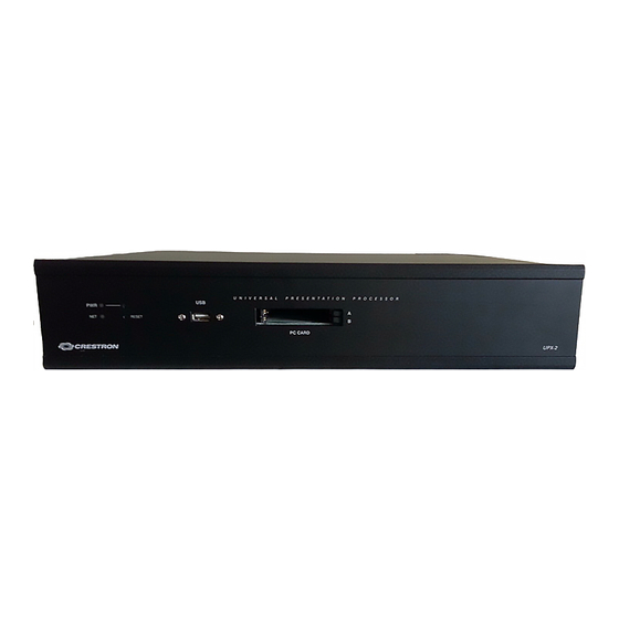
Page 32: Physical Description
FTP site). Physical Description The UPX-2, shown in the following illustrations, is housed in a black metal enclosure. The rear panel has RS-232, video, LAN, USB, 1394b, and Cresnet connectors. The front panel has a PWR (green) LED and a NET (yellow) LED. The PWR LED illuminates when power is applied to the unit. -
Page 33: Ports – Rear Panel
For additional details, refer to “Network Wiring” on page 20. Pins 24 and G provide 24 VDC and ground. Pins Y and Z provide communications (data). NOTE: The UPX-2 does not use, or supply power to the 24 VDC Cresnet connection. Operations Guide – DOC. 6276B Universal Presentation Processor: UPX-2 ¥... -
Page 34: Rgb Output A And B
Crestron UPX-2 NOTE: The UPX-2 is only compatible with 2-Series control systems. DB9 male connector provides hardware and software handshaking bidirectional Pin 1 support for RS-232, RS-422, and RS-485. This connector can be used for the touch out command (Touch the PC application) as well as local serial device control. -
Page 35: Rgb Input A And B
DESCRIPTION Red video input Green video input Blue video input , and must use the same group of A, B, and C connectors. HDTV Component Universal Presentation Processor: UPX-2 ¥ 13 Crestron UPX-2 DESCRIPTION Not Connected Not Connected DOC Clock... - Page 36 Pin 1 USB 2.0 Three Universal Serial Bus (USB) “A” connectors on the rear of the UPX-2 provide a communications link to the DualTouch Technology touchpanels (DTT) and third- party peripherals. USB is a connectivity specification developed by the USB Implementers Forum that provides a single, simple, standardized way to connect up to 127 devices to a computer.
-
Page 37: Audio Mic
100 meters over CAT5. Many peripheral devices now come equipped to meet IEEE 1394b. Implementations of IEEE 1394b, which include FireWire™ and i.Link™, are not supported in the first release of the UPX-2. Additional functionality/compatibility will be available in future firmware releases. 1394 Connector Pinout AUDIO MIC The Audio Mic (Microphone) input is one simplex powered 3.5 mm TRS mini... -
Page 38: Audio Line In And Out
NOTE: The UPX-2-1GB and UPX-2-MSO include 1GB compact flash cards. Other UPX-2 models with 512MB compact flash can be upgraded to the 1GB compact flash with either Crestron part number UPX-OS1GB or part number UPX-OS1GB- MSO which are available from Crestron. For ordering information, contact Crestron. -
Page 39: Ports, Indicators And Buttons – Front Panel
USB interface. When a device is inserted (for example, a PC-Card in the front ports of the UPX-2), a drive letter is assigned by the UPX-2 for access to that storage. The first device is assigned the drive letter G. -
Page 40: Industry Compliance
Crestron UPX-2 A front panel Power LED indicates when power is applied to the UPX-2 via the AC power cord connection. Press and hold the momentary power on/off button for five seconds to shut down the system (overrides the main off switch on the rear). Press momentarily to restart. -
Page 41: Setup
Apply the feet near the corner edges on the underside of the unit. Two rack “ears” are provided with the UPX-2 so that the unit can be rack mounted. These ears must be installed prior to mounting. Complete the following procedure to attach ears to the unit. -
Page 42: Network Wiring
Cresnet power usage of the entire chain. If the unit is a home-run from a Crestron system power supply network port, the Cresnet power usage of that unit is the Cresnet power usage of the entire run. The wire gauge and the Cresnet power usage of the run should be used in the following equation to calculate the cable length value on the equation’s left side. -
Page 43: Crestron Toolbox
ID of each unit must match an ID code specified in the SIMPL Windows program. Refer to “Setting the Net ID in Device Settings” in the latest version of the UPX-2 Reference Guide (Doc. 6286) for details of the SIMPL Windows procedure. - Page 44 Crestron UPX-2 The Net ID of the UPX-2 has been factory set to 03. The Net IDs of multiple UPX-2s in the same system must be unique. Net IDs are changed from a personal computer (PC) via Crestron Toolbox. NOTE: For detailed information on establishing communication between the PC, control system, and the UPX-2, refer to “Establishing Communications Between the...
-
Page 45: Configuring The Upx-2
Repeat this procedure for each additional network device requiring a Net ID change. Crestron Toolbox can also be used to set Net IDs with the SETUP button on the rear panel. For instructions, refer to the Crestron Toolbox help file. - Page 46 If a project is running, the SETUP MENU can be accessed using one of three methods: Via Touch Screen Via USB Keyboard 24 ¥ Universal Presentation Processor: UPX-2 Universal Presentation Processor 1. At unit startup, when the “Project Loading” progress bar and time countdown is displayed, press and hold your finger on the touchpanel display until the text “Loading Setup Screen”...
- Page 47 NOTE: If the SETUP MENU is not displayed in the center of the screen, refer to the note on page 26 for instructions on adjusting the display. 1. Establish communication with the UPX-2 as described in “Establishing Communications Between the PC and the UPX-2” on page 59.
- Page 48 CAUTION: At power up or reboot, the touchpanel will cycle through colors and the Crestron logo screen for approximately 2.5 minutes prior to displaying the progress bar. This is a normal part of the boot up process. Do not turn off power to the UPX-2 while is rebooting. Damage may occur.
- Page 49 Universal Presentation Processor SETUP MENU Details The SETUP MENU allows configuration of the UPX-2’s settings for security, Cresnet, RS-232 communications, display, runtime project, video, audio, annotation, and embedded applications. Security The Security button opens the “Security Setup” window, which allows the user to...
- Page 50 Internet access. A proxy server acts as an intermediary between your internal network (intranet) and the Internet, retrieving files from remote Web servers. 28 ¥ Universal Presentation Processor: UPX-2 Universal Presentation Processor to browse for the new network connection.
- Page 51 Cresnet communications. The communication mode is factory set to Enable. Operations Guide – DOC. 6276B 1. Enter the IP address or name of the proxy server. 2. If desired, specify addresses that should not use the proxy server (i.e. intranet addresses). Universal Presentation Processor: UPX-2 ¥ 29 Crestron UPX-2...
-
Page 52: Touch Screen
SIMPL Windows program of the Cresnet system. Matching IDs between touchpanel and SIMPL Windows program is required if data is to be successfully transferred. The Net ID for the UPX-2 is factory set to 03. No two devices in the same system can have the same Net ID. - Page 53 CAUTION: At power up or reboot, the touchpanel will cycle through colors and the Crestron logo screen for approximately 2.5 minutes prior to displaying the progress bar. This is a normal part of the boot up process. Do not turn off power to the UPX-2 while it is rebooting. Damage may occur.
- Page 54 If a device’s configuration requires changes to be made, select the device and click Modify… to open the device’s “Configure Device” window. NOTE: Only one third party touchpanel can be connected to the UPX-2 at a time. Before adding a new third party touchpanel, the existing touchpanel entry must be removed by clicking Remove….
-
Page 55: Display Output
Type drop-down list. If applicable, the Port field will indicate which of the UPX-2’s serial ports should be connected to the device. USB devices can be enabled or disabled by checking or unchecking the Enable box. - Page 56 NOTE: If the screen does not fit properly, adjust the resolution. Select Project Permits the selection of the UPX-2 program, a .vtz file. The default file location is the internal flash. To select a project from the internal flash, select Browse and select the compiled project to be loaded.
-
Page 57: Rgb Video
The selected input is shown on output B. The “RGB/Video Setup” window can be brought up and hidden using reserved joins from within a project. Refer to the latest version of the UPX-2 Reference Guide (Doc. 6286) which is available from the Crestron website. - Page 58 All inputs are adjusted for brightness and contrast. Red, green and blue are individually adjusted for an RGB input. Hue and saturation are adjusted for composite, S-video and component video inputs. 36 ¥ Universal Presentation Processor: UPX-2 Universal Presentation Processor Operations Guide – DOC. 6276B...
- Page 59 If a matching preset is not found, the UPX-2 will automatically calibrate for the RGB source. These settings will be stored as the last-recalled settings.
- Page 60 (frames per second), and whether the signal is interlaced or deinterlaced. The UPX-2 will search through all of the presets that are defined for the detected settings. If a matching preset is found, the preset will be 38 ¥...
- Page 61 If a matching preset is not found, the UPX-2 will automatically set the default settings for a video signal (brightness = 0, contrast = 0, hue = 0, and saturation = 0).
- Page 62 Defaults are +25 for volume and zero for balance. “Audio Setup” Window Annotation The Annotation button displays the “MediaMarker Session Information” window. “MediaMarker Session Information” Window 40 ¥ Universal Presentation Processor: UPX-2 Operations Guide – DOC. 6276B...
- Page 63 Each new frame title will contain the frame prefix followed by a sequential frame number. The frame template serves as a starting point for each new frame. Crestron supplies some ready-made templates, or you can use one of your own.
- Page 64 NOTE: To use effects, annotation animation must be enabled by the control system program or a control on a UPX-2 touchpanel project. When using a DTT touchpanel or a mouse, the functions of the buttons on the stylus or mouse can be defined in the Pen/Mouse Functions section of the “Preferences”...
- Page 65 “Embedded Apps” Window (UPX-2-MSO shown) NOTE: UPX-2-MSO models will have a button labeled Activate Microsoft Office. For more information, refer to “Office Activation (UPX-2-MSO only)” on page 45. Internet Explorer Security Settings Three security levels, high, medium, and low can be selected for each of the three zones, Internet, intranet, and trusted sites.
- Page 66 CAUTION: At power up or reboot, the touchpanel will cycle through colors and the Crestron logo screen for approximately 2.5 minutes prior to displaying the progress bar. This is a normal part of the boot up process. Do not turn off power to the UPX-2 while it is rebooting. Damage may occur.
- Page 67 NOTE: Save & Reboot on the SETUP MENU must be selected for Embedded Apps changes to take effect. NOTE: While browsing the Internet with the UPX-2, clicking on a link may cause a message box titled "Restrictions" to appear that contains the text "This operation has been cancelled due to restrictions in effect on this computer.
-
Page 68: Ethernet Details
Crestron UPX-2 ETHERNET Details The ETHERNET MENU allows configuration of the UPX-2’s settings for Ethernet communications. Ethernet Press the Ethernet button to access the “Ethernet Setup” window. Changes are made in real time and there is typically no need to reboot. The Ethernet address and mask are displayed on this screen. - Page 69 TCP monitors and ensures correct transfer of data. IP receives the data from TCP, breaks it up into packets, and Operations Guide – DOC. 6276B Crestron UPX-2 Universal Presentation Processor: UPX-2 ¥ 47...
- Page 70 (Doc. 6256) for more information on IP tables. “IP Table Setup” Window The IP ID is the ID number that is used to identify the UPX-2 in a control system’s IP table. The IP ID should match the IP ID set in the control system’s SIMPL Windows program.
- Page 71 Warning: An event occurred that may affect the normal operation of the unit. • Error: An operation has failed. • Fatal: An event occurred which will require the unit to be reset. Universal Presentation Processor: UPX-2 ¥ 49 Crestron UPX-2...
- Page 72 Exit the on-screen keyboard by selecting File | Exit. On-Screen Keyboard NOTE: If Ctrl+Alt+Shift is selected from the onscreen keyboard, user accounts and passwords can no longer be typed from the onscreen keyboard or an external keyboard. 50 ¥ Universal Presentation Processor: UPX-2 Operations Guide – DOC. 6276B...
- Page 73 CAUTION: At power up or reboot, the touchpanel will cycle through colors and the Crestron logo screen for approximately 2.5 minutes prior to displaying the progress bar. This is a normal part of the boot up process. Do not turn off power to the UPX-2 while it is rebooting. Damage may occur.
-
Page 74: Hardware Hookup
The ratings on the connecting unit's supply input should be considered to prevent overloading the wiring. NOTE: The UPX-2 occupies two rack spaces. Rear Side Connectors COM:... -
Page 75: Extending The Vga And Usb Cables
Universal Presentation Processor NOTE: Certain USB flash drives may not be recognized by the UPX-2 if they are left connected during a reboot or when power is cycled. To recognize a USB flash drive that is not recognized by the UPX-2, disconnect and reconnect the drive after the UPX-2 has completed rebooting. -
Page 76: Composite Video Connections
NOTE: Do not use a hub with a USB extender. Extending RGB & USB Cables Composite Video Connections The UPX-2 has six composite video inputs available. All six connectors may be used as composite video inputs. Refer to the following diagram. 54 ¥ Universal Presentation Processor: UPX-2... -
Page 77: S-Video Connections
NOTE: If you are using a 4-pin DIN S-video cable, you will need to use a 4-pin (female) DIN to BNC adapter (adaptor not included). S-Video Connections Operations Guide – DOC. 6276B VIDEO INPUT 1/HDTV VIDEO INPUT 1/HDTV VIDEO INPUT 2 S-Video 1 Universal Presentation Processor: UPX-2 ¥ 55 Crestron UPX-2 VIDEO INPUT 2 S-Video 2... -
Page 78: Component Video Connections
1 Component, 1 S-Video & Composite 1 1 Composite 56 ¥ Universal Presentation Processor: UPX-2 Universal Presentation Processor Component Video Connections When connecting Component video, connect one set of Y, P connectors. Only VIDEO INPUT 1 supports HDTV. Refer to the following diagram. -
Page 79: Setting Up A Projector For The Upx-2
3. Set the resolution to the projector’s native resolution. 4. Select the “Grid” test pattern on the UPX-2 and adjust the vertical & horizontal position on the projector. Do not adjust the size if the UPX-2 is set to the projector’s native resolution. -
Page 80: Programming
Crestron UPX-2 Programming For programming tips and reference information, refer to the latest revision of the UPX-2 Reference Guide (Doc. 6286) which is available from the Crestron website. 58 ¥ Universal Presentation Processor: UPX-2 Universal Presentation Processor Operations Guide – DOC. 6276B... -
Page 81: Uploading And Upgrading
1GB compact flash operating system with the procedures described in this section. For instructions or upgrading a compact flash operating system, refer to the latest version of the UPX-2 1GB Memory & Operating System Upgrade Installation Guide (Doc. 6443). -
Page 82: Serial Communication Setup
Communications Connections Serial Communication Setup A PC can be directly connected to the AUX COM port of the UPX-2 using a null- modem cable. NOTE: You must connect a PS/2 keyboard and mouse to the UPX-2 to establish communication for the first time. - Page 83 Console to establish communications and upload programming via the serial connection. In the Console Settings box, select the Baud Rate (115200), select Parity (None), select Data Bits (Eight), select Stop Bits (One), and enable RTS/CTS. Universal Presentation Processor: UPX-2 ¥ 61 Crestron UPX-2...
- Page 84 This is a normal part of the boot up process. Do not turn off power to the UPX-2 while it is rebooting. Damage may occur. NOTE: If you are going to use the serial port (AUX COM) for a touchpanel, you must return to this window, choose 3 Screen / Tablet, and Save &...
- Page 85 Select RS232 as the Connection Type and select the serial settings specified in step 5. This sets the PC to the same serial settings. Enter the settings and click OK. Crestron Toolbox Address Book Setup for Serial Connection Click the System Info icon and select UPX2 from the drop-down list if it is not already selected.
-
Page 86: Tcp/Ip Communication
Crestron UPX-2 TCP/IP Communication This section explains how to configure a UPX-2 to communicate over Ethernet using TCP/IP. These procedures assume that the UPX-2 has been powered up and connected as shown on page 60. 64 ¥ Universal Presentation Processor: UPX-2... - Page 87 CAT5 straight through cables with 8-pin RJ-45 connectors to connect the LAN port on the UPX-2 and the LAN port on the PC to the Ethernet hub. Alternatively, you can use a CAT5 crossover cable to connect the two LAN ports directly, without using a hub.
- Page 88 1. Select Functions | IP Table Setup from the Crestron Toolbox menu bar. “IP Table” Window 2. If the UPX-2 already has an IP table, it is displayed at the top of the window. 3. Click Add Entry to add a new IP table entry or select an existing IP entry from the list and click Modify Entry.
- Page 89 6. Repeat this procedure for all of the control systems that will control the UPX-2. 7. Click Save To File… on the “IP Table” window to save this IP table to the Universal Presentation Processor: UPX-2 ¥ 67 Crestron UPX-2...
-
Page 90: Troubleshooting Communications
8. Once all of the control systems have been listed, click Send to Device on the “IP Table” window to upload the IP table to the UPX-2. The UPX-2 will reboot and all of the table entries will be listed in black. -
Page 91: Uploading A Vt Pro-E Project
The compiled VT Pro-e project file is uploaded to the UPX-2 with Crestron Toolbox. While the UPX-2 can use project files that are located on a removable drive or a network drive, projects loaded with Crestron Toolbox become the default UPX-2 project. -
Page 92: Firmware Upgrade
Crestron UPX-2 Firmware Upgrade To take advantage of all the UPX-2 features, it is important that the unit contains the latest firmware available. Please check the Crestron website for the latest version of firmware. Not every product has a firmware upgrade, but as Crestron improves functions, adds new features, and extends the capabilities of its products, firmware upgrades are posted. - Page 93 (i.e. greater than 15-20 minutes). NOTE: UPX-2 firmware can only be downgraded to similar version numbers (i.e., the first three digits must match). For example, 2.08.009 can be downgraded to 2.08.006. However, 2.10 cannot be downgraded to 2.09.
-
Page 94: Operation
You can use the Crestron MediaMarker Notebook software with the UPX-2 and DTT products or on your own personal computer. In addition to containing the tools required for object creation, Crestron Notebook software can import graphics and text from many other applications. -
Page 95: Security Infrastructure
Crestron website. Security Infrastructure Since the UPX-2 does not use a traditional hard drive, but rather an image that gets restored every time the UPX-2 is rebooted, any virus infection is cleared immediately after a reboot. However, using the currently available tools and techniques, Crestron has provided an infrastructure that protects against possible virus infections. -
Page 96: Problem Solving
Crestron UPX-2 Problem Solving Troubleshooting The following table provides corrective action for possible trouble situations. If further assistance is required, please contact a Crestron customer service representative. UPX-2 Troubleshooting UPX-2 does not respond to ping command. Mouse or touchpanel does not work. -
Page 97: Restoring Upx-2 Default Settings
Hostname and Workgroup name: The hostname and workgroup name of the touchpanel will reset to their factory defaults. CAUTION: Do not turn off power to the UPX-2 while it is restoring the default settings. Damage may occur. Universal Presentation Processor: UPX-2 ¥ 75... -
Page 98: Further Inquiries
For assistance in your local time zone, refer to the Crestron website (www.crestron.com) for a listing of Crestron worldwide offices. You can also log onto the online help section of the Crestron website to ask questions about Crestron products. First-time users will need to establish a user account to fully benefit from all available features. -
Page 99: Appendix: Video Definitions
Input synchronization for the UPX-2 can be horizontal and vertical (H&V), composite sync, or sync on G. Output sync of the UPX-2 is always H&V. Composite (480i) and S-Video Compression of all of the video information (luminance and chrominance) into one signal was devised in the early days of color television to permit transmission over the airwaves. -
Page 100: Sdtv (Standard Definition Television)
"painted" by an electron beam every 1/60 of a second. ). To use a 720p resolution with the UPX-2 it must be first converted to RGB. Crestron recommends a converter made by Key Digital Systems, model number KD-CTCAL (www.keydigital.com) for this... -
Page 101: Composite Video
EDTV (Enhanced Definition Television). It is recommend that you use the 480i signal from the DVD (or other device) that has 480p and allow the UPX-2 to line-double the signal. The UPX-2 has a better line-doubler than most others. - Page 102 Some de-interlacers simply rearrange fields by creating an even-line output frame and an odd-line output frame every 60th of a second. Any motion occurring in the time between the odd and even fields results in undesirable motion artifacts. 80 ¥ Universal Presentation Processor: UPX-2 Universal Presentation Processor second...
-
Page 103: Aspect Ratios
16 mm Film 1.33 35 mm Film (before 1953) 1.33 35 mm Film (USA) 1.85 35 mm Film (Anamorphic) 2.35 70 mm Film 1.85 NTSC Video 1.33 PAL Video 1.33 HDTV 1.78 Universal Presentation Processor: UPX-2 ¥ 81 Crestron UPX-2... -
Page 104: Letterbox Display
Figure 3. 4:3 Aspect Ratio Displayed on a 16:9 Display 4:3 Aspect Ratio on a 16:9 Display The UPX-2 displays a true 16:9 aspect ratio. The 16:9 aspect ratio is full screen; the image fills the screen from edge to edge. Letterbox Display A letterbox image is scaled to fit within another aspect ratio, usually the standard television format of 4:3, and has reduced vertical resolution. -
Page 105: Dvd Disks
To display a full screen image, the DVD disk must be formatted as HDTV (16:9 aspect ratio). Camcorders The normal mode for camcorders is a 4:3 aspect ratio. Most new models have a wide mode setting for 16:9. Operations Guide – DOC. 6276B Letterbox (4:3) Universal Presentation Processor: UPX-2 ¥ 83 Crestron UPX-2... -
Page 106: Software License Agreement
This Agreement may only be modified by a writing signed by an authorized officer of Crestron. Updates may be licensed to You by Crestron with additional or different terms. This is the entire agreement between Crestron and You relating to the Software and it supersedes any prior representations, discussions, undertakings, communications or advertising relating to the Software. - Page 107 “applets” incorporated into the Software), the accompanying media and printed materials, and any copies of the Software are owned by Crestron or its suppliers. The Software is protected by copyright laws and international treaty provisions. Therefore, you must treat the Software like any other copyrighted material, subject to the provisions of this Agreement.
-
Page 108: Return And Warranty Policies
CRESTRON shall not be liable to honor the terms of this warranty if the product has been used in any application other than that for which it was intended, or if it has been subjected to misuse, accidental damage, modification, or improper installation procedures. -
Page 109: Microsoft ® Windows ® Xp Embedded End User License Agreement
Restricted Functionality. You are licensed to use the SOFTWARE to provide only the limited functionality (specific tasks or processes) for which the DEVICE has been designed and marketed by Crestron. This license specifically prohibits any other use of the SOFTWARE, or inclusion of additional software programs or functions, on the DEVICE. Subject to the terms of the “Limited Use of Particular Services”... - Page 110 SOFTWARE after the date you obtain your initial copy of the SOFTWARE (“Supplemental Components”). o If Crestron provides or makes available to you Supplemental Components and no other EULA terms are provided along with the Supplemental Components, then the terms of this EULA shall apply.
-
Page 111: Index
RGB ...77 RGB INPUT A and B ...13 RGB OUTPUT A and B ...12 SDTV (Standard Definition Television) ...78 Serial Communication... viii Setting the Net ID ...22 Software License Agreement ...84 Specifications...7 S-Video Connections ...55 Universal Presentation Processor: UPX-2 ¥ 89... - Page 112 Crestron UPX-2 Troubleshooting... 74 UPX-2 Quick Start...iii USB 2.0 ... 14 90 ¥ Universal Presentation Processor: UPX-2 Universal Presentation Processor VIDEO INPUT 1 ...13 Y, P Component Video ...77 Operations Guide – DOC. 6276B...
- Page 113 Universal Presentation Processor Crestron UPX-2 This page is intentionally left blank. Operations Guide – DOC. 6276B Universal Presentation Processor: UPX-2 ¥ 91...
- Page 114 Crestron Electronics, Inc. Operations Guide – DOC. 6276B 15 Volvo Drive Rockleigh, NJ 07647 (2010761) Tel: 888.CRESTRON 06.06 Fax: 201.767.7576 Specifications subject to www.crestron.com change without notice.
Need help?
Do you have a question about the UPX-2 and is the answer not in the manual?
Questions and answers