
Related Manuals for Crestron DIN Rail Control Processor DIN-AP2


Summary of Contents for Crestron DIN Rail Control Processor DIN-AP2
- Page 1 Crestron Green Light™ DIN-AP2 DIN Rail Control Processor Operations & Installation Guide...
- Page 2 This document was prepared and written by the Technical Documentation department at: Crestron Electronics, Inc. 15 Volvo Drive Rockleigh, NJ 07647 1-888-CRESTRON All brand names, product names and trademarks are the property of their respective owners. ©2008 Crestron Electronics, Inc.
-
Page 3: Table Of Contents
Crestron DIN-AP2 Contents Crestron Green Light™ DIN Rail Control Processor: DIN-AP2 Introduction ... 1 Features and Functions ... 1 Applications... 4 Specifications ... 5 Physical Description... 7 Industry Compliance ... 12 Setup ... 13 Network Wiring... 13 Installation ... 13 Hardware Hookup ... -
Page 5: Crestron Green Light™ Din Rail Control Processor: Din-Ap2
Crestron DIN-AP2 Crestron Green Light™ DIN Rail Control Processor: DIN-AP2 Introduction The DIN-AP2 is a 2-Series control processor designed for small to medium-sized lighting and automation applications. DIN rail mounting enables modular installation alongside Crestron automation control modules and other third-party DIN rail mountable devices. -
Page 6: Din Rail Installation
DIN Rail Control Processor 2-Series Processor Built upon Crestron’s reliable 2-Series control engine, the DIN-AP2 is extensively programmable using Crestron’s suite of powerful development software and vast database of drivers and software modules. The DIN-AP2 works seamlessly with Crestron’s entire line of lighting dimmers and shade controls, keypads and touchpanels, thermostats, wireless gateways, and expansion modules. - Page 7 Crestron DIN-AP2 Cresnet Power Supply is required to power the DIN-AP2 and any connected Cresnet devices. Ethernet and e-Control Built-in 10/100 Ethernet facilitates secure high-speed network connectivity, enabling extensive capabilities for remote system maintenance and control, and providing an interface to other Crestron control systems.
-
Page 8: Applications
DIN Rail Control Processor Applications The following diagram shows a DIN-AP2 in a typical application. DIN-AP2 in a Typical Application 4 • DIN Rail Control Processor: DIN-AP2 Crestron DIN-AP2 Operations & Installation Guide – DOC. 6662A... -
Page 9: Specifications
Crestron DIN-AP2 Specifications Specifications for the DIN-AP2 are listed in the following table. DIN-AP2 Specifications SPECIFICATION Memory SDRAM NVRAM Flash Removable Storage Operating System Ethernet Power Requirements Cresnet Power Usage Environmental Temperature Humidity Heat Dissipation (Continued on following page) Operations & Installation Guide – DOC. 6662A DIN Rail Control Processor DETAILS 32-bit Freescale ColdFire... -
Page 10: Specification
DIN Rail Control Processor DIN-AP2 Specifications (Continued) SPECIFICATION Enclosure Dimensions Height Width Depth Weight Available Accessories DIN-BLOCK DIN-HUB DIN-PWS50 DIN Rail Series IRP2 6 • DIN Rail Control Processor: DIN-AP2 Crestron DIN-AP2 DETAILS Light gray polycarbonate housing with polycarbonate label overlay, UL94 V-0 rated, 35 mm DIN EN 60715 rail mount, DIN 43880 form factor for enclosures with 45 mm... -
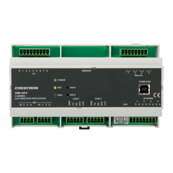
Page 11: Physical Description
Crestron DIN-AP2 Physical Description This section provides information on the connections, controls and indicators available on your DIN-AP2. DIN-AP2 Physical View DIN-AP2 Overall Dimensions Operations & Installation Guide – DOC. 6662A DIN Rail Control Processor 159 mm (6.26 in) DIN Rail Control Processor: DIN-AP2 • 7 58 mm (2.28 in) 94.2 mm... - Page 12 DIN Rail Control Processor Connectors, Controls & Indicators CONNECTORS CONTROLS & INDICATORS I/O VERSIPORTS 1-8 (Continued on following page) 8 • DIN Rail Control Processor: DIN-AP2 (1) 9-pin 3.5mm detachable terminal block comprising (8) digital input/output or analog input ports (referenced to GND) Max Wire Size: 1.5 mm (16 AWG) Digital Input:...
- Page 13 Crestron DIN-AP2 Connectors, Controls & Indicators (Continued) CONNECTORS CONTROLS & INDICATORS (Continued on following page) Operations & Installation Guide – DOC. 6662A DIN Rail Control Processor MSG LED (1) Red LED, illuminates when a message is present in the message log. To view the contents of the message log, use Crestron Toolbox™.
- Page 14 DIN Rail Control Processor Connectors, Controls & Indicators (Continued) CONNECTORS CONTROLS & INDICATORS COM1 & COM 2 (Continued on following page) 10 • DIN Rail Control Processor: DIN-AP2 (2) 5-pin 3.5 mm detachable terminal blocks, bidirectional comprising (2) RS-232 ports Max Wire Size: 1.5 mm (16 AWG) Up to 115.2k baud...
- Page 15 Crestron DIN-AP2 Connectors, Controls & Indicators (Continued) CONNECTORS CONTROLS & INDICATORS Pin 4 Pin 1 1. Interface connectors for NET, IR/SERIAL, COM 1, COM 2, I/O and RELAYS ports are provided with the unit. 2. The DIN-AP2 can only be powered via the NET port. Be sure to use a Crestron approved power supply as another may cause damage.
-
Page 16: Industry Compliance
DIN Rail Control Processor Industry Compliance This unit has been manufactured to comply with UL’s Standards for Safety in Canada and the United States. Formal approval is pending. As of the date of manufacture, the DIN-AP2 has been tested and found to comply with specifications for CE marking and standards per EMC and Radiocommunications Compliance Labelling. -
Page 17: Setup
Crestron DIN-AP2 Setup Network Wiring When wiring the Cresnet and Ethernet network, consider the following: • Use Crestron Certified Wire. NOTE: Cresnet-HP wire cannot be used. • Use Crestron power supplies for Crestron equipment. • Provide sufficient power to the system. CAUTION: Insufficient power can lead to unpredictable results or damage to the equipment. - Page 18 DIN Rail Control Processor The DIN-AP2 is designed for installation on a DIN rail. Refer to the following diagram when installing. Installing the DIN-AP2 DIN RAIL RELEASE 1. Place the top of the DIN-AP2’s rail mount over the top of the DIN rail.
-
Page 19: Hardware Hookup
Crestron DIN-AP2 Hardware Hookup Connect the Make the necessary connections as called out in the illustration that Device follows this paragraph. Refer to “Network Wiring” on page 13 before attaching the 4-position terminal block connector. Apply power after all connections have been made. WARNING: Prior to connecting the device, turn off power at the circuit breaker. - Page 20 DIN Rail Control Processor Hardware Connections for the DIN-AP2 I/O: TO CONTROLLABLE FOR OPTIONAL MMC DEVICES & FROM DEVICE OUTPUTS NET: POWER FROM BI-DIRECTIONAL RS-232 DIN-PWS50 OR OTHER WITH HARDWARE & CRESNET POWER SUPPLY . SOFTWARE HANDSHAKING PASS-THROUGH TO OTHER CRESNET DEVICES NOTE: Ensure the unit is properly grounded.
- Page 21 Crestron DIN-AP2 Versiport Depending on the application, the DIN-AP2’s Versiports can be wired Connections multiple ways. Refer to the following diagrams when wiring a Versiport. WARNING: Incorrect wiring may damage the DIN-AP2 or the connected device. NOTE: The settings for input/output and the pull-up resistor are specified in the control system program.
- Page 22 DIN Rail Control Processor Versiport Wiring Diagrams—Analog Input Function Reading a voltage from an analog source 10V DC I/O Setup: Analog Input Pull-up Resistor: Disabled Versiport Wiring Diagrams—Digital Output Function Driving a relay 24V DC Max. I/O Setup : Digital Output Pull-up Resistor: Disabled 18 •...
-
Page 23: Programming Software
Crestron DIN-AP2 Programming Software Have a question or comment about Crestron software? Answers to frequently asked questions (FAQs) can be viewed in the Online Help section of the Crestron website. To post a question or view questions you have submitted to Crestron’s True Blue Support, log in at http://support.crestron.com. -
Page 24: Programming With Crestron Systembuilder
DIN Rail Control Processor Programming with Crestron SystemBuilder Crestron SystemBuilder is the easiest method of programming but does not offer as much flexibility as SIMPL Windows. For additional details, download SystemBuilder from the Crestron website and examine the extensive help file. Programming with D3 Pro Crestron’s D3 Pro lighting software provides all the tools necessary to create a complete Crestron lighting system for residential applications. - Page 25 Crestron DIN-AP2 Locating the DIN-AP2 in the Device Library Program Program Manager is the view where programmers “program” a Crestron Manager control system by assigning signals to symbols. The symbol can be viewed by double clicking on the icon or dragging it into Detail View.
-
Page 26: Uploading And Upgrading
DIN Rail Control Processor Uploading and Upgrading Crestron recommends using the latest programming software and that each device contains the latest firmware to take advantage of the most recently released features. However, before attempting to upload or upgrade it is necessary to establish communication. Once communication has been established, files (for example, programs or firmware) can be transferred to the control system (and/or device). - Page 27 Crestron DIN-AP2 marked Ethernet however, communications must be established in order to see this information in the “System Info” window. • Display the DIN-AP2’s “System Info” window (click the icon); communications are confirmed when the device information is displayed. TCP/IP Ethernet Communication PC RUNNING CRESTRON...
-
Page 28: Programs And Firmware
DIN Rail Control Processor Programs and Firmware Program or firmware files may be distributed from programmers to installers or from Crestron to dealers. Firmware upgrades are available from the Crestron website as new features are developed after product releases. One has the option to upload programs via the programming software or to upload and upgrade via the Crestron Toolbox. -
Page 29: Problem Solving
Crestron DIN-AP2 Problem Solving Troubleshooting The following table provides corrective action for possible trouble situations. If further assistance is required, please contact a Crestron customer service representative. DIN-AP2 Troubleshooting TROUBLE Unexpected response from control system. PWR LED does not illuminate. (Continued on following page) Operations &... - Page 30 DIN Rail Control Processor DIN-AP2 Troubleshooting (Continued) TROUBLE MSG LED illuminates. System locks up. Various. (Continued on following page) 26 • DIN Rail Control Processor: DIN-AP2 POSSIBLE CAUSE(S) Hardware or Verify that hardware software failure, configuration matches hardware software configuration. incompatibility with Use Crestron Toolbox software...
- Page 31 Crestron DIN-AP2 DIN-AP2 Troubleshooting (Continued) TROUBLE Cresnet device does not respond. System Monitor The System Monitor allows you to reload firmware into the DIN-AP2 in the event that you cannot load the firmware in the normal mode. If the system does not function, perform the following procedure: 1.
- Page 32 DIN Rail Control Processor 6. Once the DIN-AP2 is in Monitor mode, connect to the PC using a USB cable. NOTE: If at any point in the above sequence, one of the timer periods expires without the SW-R button being pressed, the unit will boot normally, first running the firmware, then loading the application.
-
Page 33: Check Network Wiring
Crestron DIN-AP2 12. Find and select the correct firmware file (.CUZ or .zip) and click Open. 13. In the “Firmware” window, click Send. You will see a “Confirmation” window asking if you’ve selected the right file. Click OK and you will see the “File Transfer” window. 14. - Page 34 DIN Rail Control Processor When calculating the length of wire for a particular Cresnet run, the wire gauge and the Cresnet power usage of each network unit to be connected must be taken into consideration. Use Crestron Certified Wire only. If Cresnet units are to be daisy-chained on the run, the Cresnet power usage of each network unit to be daisy-chained must be added together to determine the Cresnet power usage of the entire chain.
-
Page 35: Reference Documents
Crestron DIN-AP2 Reference Documents The latest version of all documents mentioned within the guide can be obtained from the Crestron website (www.crestron.com/manuals). This link will provide a list of product manuals arranged in alphabetical order by model number. List of Related Reference Documents 2-Series Control Systems Reference Guide DIN-PWS50 DIN Rail Power Supply e-Control Reference Guide... -
Page 36: Software License Agreement
DIN Rail Control Processor Software License Agreement This License Agreement (“Agreement”) is a legal contract between you (either an individual or a single business entity) and Crestron Electronics, Inc. (“Crestron”) for software referenced in this guide, which includes computer software and as applicable, associated media, printed materials and “online”... - Page 37 Crestron DIN-AP2 If You are a business or organization, You agree that upon request from Crestron or its authorized agent, You will within thirty (30) days fully document and certify that use of any and all Software at the time of the request is in conformity with Your valid licenses from Crestron of its authorized agent.
-
Page 38: Return And Warranty Policies
DIN Rail Control Processor Return and Warranty Policies Merchandise Returns / Repair Service 1. No merchandise may be returned for credit, exchange or service without prior authorization from CRESTRON. To obtain warranty service for CRESTRON products, contact an authorized CRESTRON dealer. Only authorized CRESTRON dealers may contact the factory and request an RMA (Return Merchandise Authorization) number. - Page 39 Crestron DIN-AP2 DIN Rail Control Processor This page is intentionally left blank. DIN Rail Control Processor: DIN-AP2 • 35 Operations & Installation Guide – DOC. 6662A...
- Page 40 Crestron Electronics, Inc. Operations & Installation Guide – DOC. 6662A 15 Volvo Drive Rockleigh, NJ 07647 (2020744) Tel: 888.CRESTRON 06.08 Fax: 201.767.7576 Specifications subject to www.crestron.com change without notice.
Need help?
Do you have a question about the DIN Rail Control Processor DIN-AP2 and is the answer not in the manual?
Questions and answers