Table of Contents
Advertisement
Advertisement
Table of Contents
Troubleshooting

Subscribe to Our Youtube Channel
Related Manuals for Crestron CP2


Summary of Contents for Crestron CP2
- Page 2 This document was prepared and written by the Technical Documentation department at: Crestron Electronics, Inc. 15 Volvo Drive Rockleigh, NJ 07647 1-888-CRESTRON...
-
Page 3: Table Of Contents
Troubleshooting Communications ................22 Compiling and Uploading a Program to the Control System ........24 Uploading Web pages to the CP2E ................25 Uploading Touchpanel Projects via the CP2/CP2E........... 26 Updating the Operating System................. 26 Advanced Console Commands.................. 27 Troubleshooting........................28 Passthrough Mode ..................... -
Page 5: 2-Series Integrated Control Processor: Cp2/Cp2E
CP2 and CP2E units house the control system software program and provide connectivity for communication and control of all devices on the network. The CP2E is functionally identical to the CP2, with the exception that it also provides LAN and Web access through its built-in 10/100 BaseT Ethernet port, which supports dynamic/static IP addressing and full-duplex TCP/IP and UDP/IP protocols. -
Page 6: Specifications
The enhanced SIMPL+™ instruction set is also fully compatible with existing Crestron SIMPL Windows and SIMPL+ programs. Specifications Specifications for the CP2 and CP2E are given in the following table. CP2/CP2E 2-Series Integrated Control System Specifications SPECIFICATION DETAILS ®... -
Page 7: Physical Description
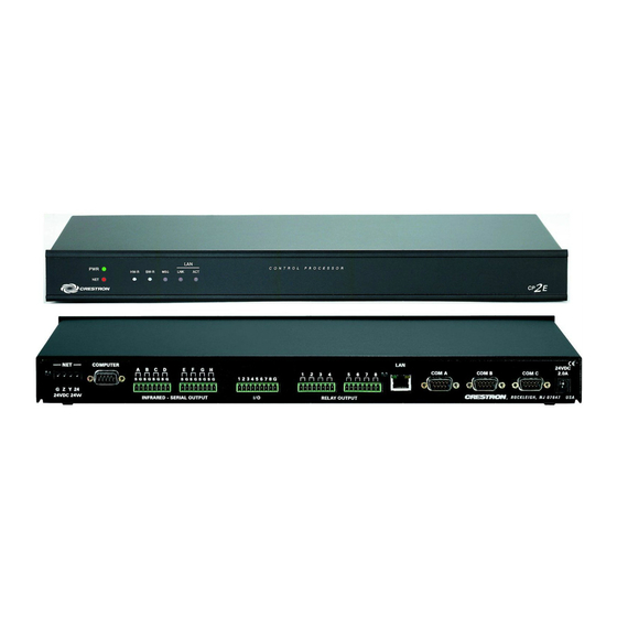
The front panels of both units include standard LEDs and two reset buttons. All connections to the units are made through their rear panels. The front panels of the CP2 and CP2E are shown below. Front and Rear Panels The front panels of the CP2 and CP2E are shown below. -
Page 8: Controls And Indicators
2-Series Integrated Control Processor Crestron CP2/CP2E Controls and Indicators The CP2/CP2E front panel indicators and controls are described below. PWR (Power) This LED illuminates when the unit is connected to and receives 24VDC power from an AC power pack or the Cresnet NET connector. - Page 9 Cresnet cable connector is properly aligned before attempting to insert it, to avoid damage to the CP2/CP2E unit. This connector (typical Crestron network port labeled G Z Y 24) is used for expansion to Cresnet and SmarTouch peripherals. This connector can also serve as a...
- Page 10 These connectors provide eight normally open, isolated relay contact groups. Each relay contact closure is rated 1A, 30 VAC/DC; MOV arc suppression is provided across contacts for use with "real world" loads. 6 • 2-Series Integrated Control Processor: CP2/CP2E Operations Guide - DOC. 5980...
-
Page 11: Memory
24VDC 2.0A This male connector can be used to supply 24VDC power to the CP2/CP2E from an AC power pack purchased separately. (Refer to Optional Power Supply on page 13). When power is supplied to the units through this connector, 24VDC, 24W is also available to other Cresnet system devices through the NET connector. - Page 12 Volatile 1. Digital, analog and serial signal values 2. SIMPL+ Variables (Default if no options are specified, or if "volatile" qualifier is used, or #DEFAULT_VOLATILE is used) 8 • 2-Series Integrated Control Processor: CP2/CP2E Operations Guide - DOC. 5980...
-
Page 13: Industry Compliance
Industry Compliance As of the date of manufacture, the CP2/CP2E integrated control processors have been tested and found to comply with specifications for CE marking and the Australian Compliance Mark. -
Page 14: Bussing Strip Installation
To prevent the possibility of electrical shorts, it is essential that these conductors do not touch any uninsulated portion of the bussing strip. 10 • 2-Series Integrated Control Processor: CP2/CP2E Operations Guide - DOC. 5980... -
Page 15: Network Wiring
Network Interconnect Drawing (Doc. 5411). The document can be obtained from the Downloads section of the Crestron website (www. crestron.com). Search for the CRESNET.PDF files. CAUTION: Exceeding the power output (maximum 24W) of the CP2/CP2E can result in system shutdown or a blown fuse. CAUTION: Possible equipment damage if miswired. -
Page 16: Hardware Hookup
INFRARED - SERIAL OUTPUT RELAY OUTPUT CRESTRON, ROCKLEIGH, NJ 07647 TO CONTROLLABLE DEVICES IRP2 CONTROLLABLE FROM DEVICE DEVICES SERIAL OUTPUTS DEVICES - CONTACT CLOSURES - SOLID STATE CLOSURES 12 • 2-Series Integrated Control Processor: CP2/CP2E Operations Guide - DOC. 5980... -
Page 17: Optional Power Supply
(Optional) DEAL for Windows IR learning software version 2.07 CP2/CP2E Device Library Symbols In Configuration Manager, drag the CP2 or CP2E from the Control Systems folder of the Device Library to System Views. The CP2 and CP2E appear nearly identical, except that the CP2E provides an additional slot for Ethernet devices, as shown below. - Page 18 To add an IR device to the system, drag the device driver from the Crestron or User IR Database to a C2I-IR8 port. To add an RS-232 device, drag the C2IR one-way serial driver from the Serial Drivers folder to a C2I-IR8 port.
- Page 19 2-Series Integrated Control Processor Slot 3: C2I-IO8 The CP2 and CP2E provide eight I/O ports called Versiports, each of which can function as a digital input, a digital output, or an analog input. Each Versiport has a corresponding pullup resistor.
- Page 20 Rather, the <MinChange> signals should be used to specify a "minimum change" value, such that the C2I-IO8 will not propagate the new value until it changes by <MinChange>. (The default minimum change value is 2048.) Example 6: 16 • 2-Series Integrated Control Processor: CP2/CP2E Operations Guide - DOC. 5980...
- Page 21 IP Table. The second method is to use the Crestron Viewport. This method is especially useful on site, if you want to change one or more IP addresses without changing the program.
-
Page 22: Converting Programs And Modules Created For Other Systems
To do this you first open the program, and then replace the existing control system with the CP2 or CP2E. That is, drag the CP2 or CP2E from the Control Systems folder onto the existing control system in System Views, and click Yes when prompted to confirm the replacement. - Page 23 Although X-Series processors support ambiguous signals, the 2-Series processor requires all signal types to be strictly defined. If the program you want to convert contains SIMPL+ or User modules, Crestron recommends that you first convert each module before converting the larger program.
-
Page 24: Establishing Communication With The Cp2/Cp2E
Establishing Communication with the CP2/CP2E Before uploading a program to the CP2/CP2E or performing diagnostic functions, you must connect the control system to the PC. With the CP2, this connection must be serial; with the CP2E the connection can be either serial or TCP/IP. - Page 25 1. Open Viewport and click Functions | Set Control System IP Information. 2. Enter the IP address, IP mask and default router in the text fields. (All of these terms are explained in detail in Crestron’s e-Control Reference Guide, DOC. 6052, available as a PDF on the Crestron website.) 3.
-
Page 26: Troubleshooting Communications
CAT5 crossover cable to connect the two LAN ports directly, without using a hub. Once the cable connections are made, open the Crestron Viewport and click Setup | Communication Settings on the menu to display the “Port Settings” dialog box. - Page 27 (e.g., for a modem). Consult the manufacturer’s documentation for further information about the COM ports on your 3. Check the ERR LED indicator on the front panel of the CP2/CP2E. If this LED is illuminated, unplug the unit and reapply power after a few seconds.
-
Page 28: Compiling And Uploading A Program To The Control System
“Retrieve Current Program before overwriting” check box is selected. You can also click Check Program to display the header information of the currently loaded program. “Send Program” Dialog Box 24 • 2-Series Integrated Control Processor: CP2/CP2E Operations Guide - DOC. 5980... -
Page 29: Uploading Web Pages To The Cp2E
Finally, selecting Transfer Single File can send a single HTML file. Browse to the file and click Open. Then specify the file’s relative path (from the root directory) and click OK. Operations Guide - DOC. 5980 2-Series Integrated Control Processor: CP2/CP2E• 25... -
Page 30: Uploading Touchpanel Projects Via The Cp2/Cp2E
Crestron CP2/CP2E Uploading Touchpanel Projects via the CP2/CP2E You can use a connection to the CP2 or CP2E to upload VisionTools Pro-e projects to any Cresnet touchpanel. Compiled projects for TPS panels are contained in VTZ files; projects for all other touchpanels are contained in HEX files. -
Page 31: Advanced Console Commands
The SIMPL Windows online help file provides a full listing of console commands that are valid for 2-Series control systems. You can access the CP2/CP2E console in a variety of ways: via a serial connection (RS-232) with a PC, over Ethernet via the LAN port, or through Telnet, among many other methods. -
Page 32: Troubleshooting
2-Series Integrated Control Processor Crestron CP2/CP2E Troubleshooting The table below and on the next page provides corrective action for possible trouble situations. If further assistance is required, please contact a Crestron customer service representative. CP2/CP2E Troubleshooting POSSIBLE TROUBLE CORRECTIVE ACTION... -
Page 33: Passthrough Mode
2-Series Integrated Control Processor Battery Replacement A Lithium battery is used to power the system clock within the CP2/CP2E. Under normal conditions, it will last for approximately 10 years. In the event that the clock fails, only an authorized technician should replace it. Refer to caution statement below. - Page 34 The PC will now be communicating directly with the device. To exit Passthrough mode, simply click Functions | Exit Passthrough Mode. A system reboot will also exit Passthrough mode. 30 • 2-Series Integrated Control Processor: CP2/CP2E Operations Guide - DOC. 5980...
-
Page 35: Further Inquiries
These updates are solely electronic and serve as intermediary supplements prior to the release of a complete technical documentation revision. Manual updates are posted in PDF format in the Product Manual area of the Crestron website (www.crestron.com). Operations Guide - DOC. 5980... -
Page 36: Software License Agreement
This Agreement may only be modified by a writing signed by an authorized officer of Crestron. Updates may be licensed to You by Crestron with additional or different terms. This is the entire agreement between Crestron and You relating to the Software and it supersedes any prior representations, discussions, undertakings, communications or advertising relating to the Software. - Page 37 “applets” incorporated into the Software), the accompanying media and printed materials, and any copies of the Software are owned by Crestron or its suppliers. The Software is protected by copyright laws and international treaty provisions. Therefore, you must treat the Software like any other copyrighted material, subject to the provisions of this Agreement.
-
Page 38: Return And Warranty Policies
CRESTRON shall not be liable to honor the terms of this warranty if the product has been used in any application other than that for which it was intended, or if it has been subjected to misuse, accidental damage, modification, or improper installation procedures. - Page 39 Crestron CP2/CP2E 2-Series Integrated Control Processor This page intentionally left blank. Operations Guide - DOC. 5980 2-Series Integrated Control Processor: CP2/CP2E• 35...
- Page 40 Crestron Electronics, Inc. Operations Guide – DOC. 5980 15 Volvo Drive Rockleigh, NJ 07647 02.02 Tel: 888.CRESTRON Fax: 201.767.7576 Specifications subject to www.crestron.com change without notice.
Need help?
Do you have a question about the CP2 and is the answer not in the manual?
Questions and answers