
Related Manuals for Icom IC-M510


Summary of Contents for Icom IC-M510
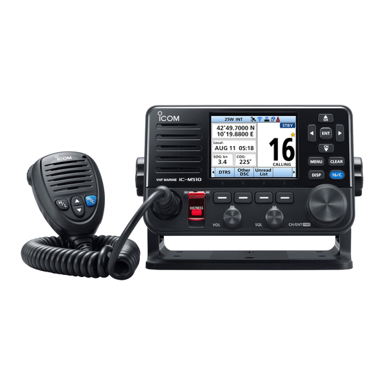
- Page 1 INSTRUCTION MANUAL VHF MARINE TRANSCEIVERS |M510 |M510E This device complies with Part 15 of the FCC Rules. Operation is subject to the condition that this device does not cause harmful interference.
-
Page 2: Important
Thank you for choosing this Icom product. This product was designed and built with Icom’s state of the art technology and craftsmanship. With proper care, this product should provide you with years of trouble- free operation. ■ Important ■ Features... -
Page 3: In Case Of Emergency
■ In Case of Emergency If your vessel requires assistance, contact other vessels and the Coast Guard by sending a distress call on Channel 16 or transmit your Distress call using Digital Selective Calling (DSC) on Channel 70. D Using Channel 16 Push [16/C] to switch to Channel 16. -
Page 4: Radio Operation Warning
ANTENNAS WITH A MAXIMUM GAIN OF 9 dBi ARE USED FOR A SHIP MOUNTED SYSTEM. IC-M510 and CT-M500 RF Safety warning An internal Wireless LAN module and an antenna are supplied with the IC-M510 and CT-M500. To comply with FCC/ISED RF Exposure for the installed Wireless LAN unit, the device should be installed and operated with a minimum distance of 20 cm between the device and all persons. -
Page 5: Avertissement Pour Les Opérateurs Radio
DONT LE GAIN MAXIMAL EST DE 9 dBi. Avertissement de sécurité RF IC-M510 et CT-M500 Un module LAN sans fil interne et une antenne sont fournis avec l’IC-M510 et le CT-M500. Pour se conformer à l’exposition aux RF FCC / ISED pour l’unité LAN sans fil installée, l’appareil doit être installé... -
Page 6: Fcc Information
• Consult the dealer or an experienced radio/TV technician for help. CAUTION: Changes or modifications to this transceiver, not expressly approved by Icom Inc., could void your authority to operate this transceiver under FCC regulations. ■ Information FCC Cet appareil est conforme à la partie 15 de la réglementation FCC. Son fonctionnement est soumis à... -
Page 7: Note
In the cockpi ■ Note A WARNING STICKER is supplied with the USA version transceiver. To comply with FCC regulations, this sticker WARNING must be affixed in such a location as to be STICKER readily seen from the operating controls of the radio as in the diagram to the right. -
Page 8: Précautions
■ Wireless LAN Information ■ Précautions D Precautions on using the R AVERTISSEMENT ! NE JAMAIS relier l’émetteur-récepteur à une prise CA. Cela wireless LAN pourrait provoquer un choc électrique ou un • We recommend that users with incendie. pacemakers take precautions to be sure R AVERTISSEMENT ! NE JAMAIS that this device does not cause them brancher l’émetteur-récepteur sur une... -
Page 9: Information Sur Le Réseau Local Sans Fil
D Lieu d’installation du réseau MISE EN GARDE : La face arrière de la VHF chauffe en cas d’utilisation continue local sans fil sur une longue durée. Tenir compte des conditions d’installation MISE EN GARDE : L’émetteur-récepteur ci-dessous pour ne pas réduire la portée est étanche conformément à... -
Page 10: Installation Note
It is recommended that antenna of a maximum gain of 3 dB is used. If higher gain antenna is required then please contact your Icom distributor for revised installation recommendations. -
Page 11: Recommendation
The transceiver may lose its waterproof protection if the case or microphone is cracked or broken, the microphone connector is not screwed in completely, or the transceiver has been dropped. Contact your Icom distributor or your dealer for advice. ■ Key Icon Description The keys are described in this manual as follows: The keys that have words or letters on them are described with the characters “[ ].”... -
Page 12: Table Of Contents
■ Table of Contents ■ Important ..........i 5 SCAN OPERATION ......16 ■ Explicit Definitions ......i ■ Scan types ........16 ■ Setting Favorite channels....17 ■ Features ..........i ■ In Case of Emergency......ii ■ Starting a scan ■... - Page 13 11 WLAN SETTING ....... 88 ■ Turning the WLAN function ON ..88 ■ Setting up the IC-M510/IC-M510E WLAN mode ........88 ■ Connecting to the CT-M500 .... 92 ■ Using a mobile device as a microphone ........94 ■ Reset the WLAN settings ....95 ■...
-
Page 14: Operating Rules
OPERATING RULES D Priorities • Read all rules and regulations pertaining to priorities and keep an up-to-date copy handy. Safety and distress calls take priority over all others. • You must monitor Channel 16 when you are not operating on another channel. •... -
Page 15: Panel Description
PANEL DESCRIPTION ■ Front panel Function display (p. 4) Speaker P W R 13 12 11 10 1 DISTRESS KEY [DISTRESS] 8 DISPLAY KEY [DISP] Hold down for 3 seconds to transmit a Push to switch the main screen between Distress call. -
Page 16: Speaker Microphone
PANEL DESCRIPTION ■ Speaker Microphone Microphone Speaker 1 PTT SWITCH [PTT] (p. 13) Hold down to transmit, release to receive. 2 UP/DOWN KEYS [▲]/[▼] (p. 13) Push to select the Favorite channels, change scanning direction or manually resume a scan. L When the “FAV on MIC”... -
Page 17: Function Display (Info Screen)
PANEL DESCRIPTION ■ Function Display TIME AREA The current time is displayed when valid (INFO screen) GPS data is received, or manually enter the time. L When you switch the main screen between the INFO, the Plotter, and the Highway Indicator Description screens, push [DISP] . - Page 18 PANEL DESCRIPTION D Information area • Displayed when there are unread DSC messages. The MMSI code* and the following indicators • Blinks when a DSC message are displayed in the Information area. is received. * ATIS code is displayed if only the ATIS Displayed when the “CH Auto code is entered in NLD and FRG version.
-
Page 19: Software Keys
PANEL DESCRIPTION ■ Software Keys D Software key functions Various often-used functions are assigned Compose Distress [DTRS] (p. 22) to the Software Keys for easy access. The functions’ icons are displayed above the Push to display the “Compose Distress” Software Keys, as shown below. screen to select the nature of distress, then to make a call. - Page 20 Push to select regular channels or Weather L To use this function, the external hailer channels. speaker must be connected to the CT-M500 L The Weather channel is for only the USA connected to the IC-M510/IC-510E. versions. [CH] is displayed for other versions. LO/DX (p. 85)
-
Page 21: Preparations
PREPARATIONS For only the European version: When you turn ON the transceiver, “Model” screen is displayed depending on the setting. Select the country where you operate the transceiver. L If no country is selected, “General” is automatically selected. ■ Entering the MMSI code The Maritime Mobile Service Identity (MMSI: DSC self ID) code consists of 9 digits. -
Page 22: Entering The Atis Id (For Nld And Frg Versions)
PREPARATIONS ■ Entering the ATIS ID (For NLD and FRG versions) The Automatic Transmitter Identification System (ATIS) ID consists of 10 digits. You can enter the ID in the “ATIS ID Input” item on the Menu screen. This ID entering can be done only once. After entering, it can be changed only by your dealer or distributor. -
Page 23: Basic Operations
BASIC OPERATIONS ■ Selecting a channel D Regular Channel You can select a channel by pushing [▲] or [▼]. D Channel 16 Channel 16 is the distress and safety channel. It is used to establish the initial contact with a station, and for emergency communications. Channel 16 is monitored during both Dualwatch and Tri-watch. -
Page 24: Weather Channels And Weather Alert (For Only The Usa Versions)
BASIC OPERATIONS ■ Weather channels and Weather Alert (For only the USA versions) The USA version transceiver has 10 preset Weather channels. The transceivers are capable* of monitoring broadcasts from the National Oceanographic and Atmospheric Administration (NOAA). The transceiver automatically detects a Weather alert tone on the selected weather channel, or while scanning. -
Page 25: Adjusting The Volume/Squelch/ Backlight/Display Mode
BASIC OPERATIONS ■ Adjusting the volume/ squelch/backlight/display mode D Adjusting the volume level Rotate [VOL] to adjust the audio volume level. D Adjusting the squelch level Squelch enables the audio to be heard only while receiving a signal that is stronger than the set level. -
Page 26: Setting The Call Channel
BASIC OPERATIONS ■ Setting the Call channel By default, a Call channel is set in each Channel Group. You can set your most often-used channel as your Call channel in each Channel Group for quick recall. Open the “Call Channel” screen. [MENU] >... -
Page 27: Aquaquake
BASIC OPERATIONS ■ AquaQuake Water Draining function Water in the speaker grill may muffl e the sound coming from the speaker. The AquaQuake Water Draining function removes water from the speaker grill by vibrating the speaker cone. CAUTION: DO NOT use the AquaQuake Water Draining function when an external speaker is connected. -
Page 28: Microphone Lock Function
BASIC OPERATIONS ■ Microphone Lock function The Lock function electronically locks all keys on the microphone except [PTT] to prevent accidental channel changes or functions access. Hold down [PWR] for 1 second to turn OFF the transceiver. While holding down [H/L] on the microphone, hold down [PWR] for 1 second to turn the Lock function ON or OFF. -
Page 29: Scan Operation
SCAN OPERATION ■ Scan types You can find ongoing communication by scanning the Favorite channels. Scan is for all the transceiver versions except the NLD version. Before starting a scan : • Set the channels that you want to scan as Favorite channels. (p. 17) L Only the Favorite channels are scanned. -
Page 30: Setting Favorite Channels
SCAN OPERATION ■ Setting Favorite channels You can quickly recall often-used channels by setting them as Favorite channels. You can set Favorite channels in each Channel Group. Select a Channel Group on the Menu screen. (p. 10) [MENU] > Settings > Radio > Channel Group Push [▲] or [▼], or rotate [CH/ENT] to select the channel. -
Page 31: Dualwatch/Tri-Watch
DUALWATCH/TRI-WATCH (Except for the NLD version) ■ Description Dualwatch and Tri-watch are convenient to periodically check Channel 16 while you are operating on another channel. Tri-watch Dualwatch Call channel Operating CH 16 Operating channel channel CH 16 Periodically checks Channel Periodically checks Channel 16 and the Call channel while operating on 16 while operating on another... -
Page 32: Digital Selective Calling (Dsc)
DIGITAL SELECTIVE CALLING (DSC) ■ DSC address ID D Entering an Individual or Group ID You can enter a total of 75 Individual IDs and 25 Group IDs, and assign names to them of up to 10 characters. Open the “Individual ID” or “Group ID” screen. [MENU] >... -
Page 33: Entering The Position And Time
DIGITAL SELECTIVE CALLING (DSC) D Deleting an entered ID (Example: Deleting an Individual ID: STATION 2) Open the “Individual ID” screen. [MENU] > Settings > DSC > Individual ID Select “STATION 2,” and then push Delete • “Delete the ID. Are You Sure?” is displayed. Push to delete. -
Page 34: Sending Dsc Calls (Distress)
DIGITAL SELECTIVE CALLING (DSC) ■ Sending DSC calls (Distress) A Distress call should be sent if, in the opinion of the captain, the ship or a person is in distress and requires immediate assistance. NEVER MAKE A DISTRESS CALL IF YOUR SHIP OR A PERSON IS NOT IN AN EMERGENCY. - Page 35 DIGITAL SELECTIVE CALLING (DSC) D Regular call Select the nature of the Distress call to include in the Regular Distress call. Push DTRS • The “Compose Distress” screen is displayed. Push [ENT] or [CH/ENT] to enter the Nature selection mode. Select the nature of the Distress, and then push [ENT] or [CH/ENT].
- Page 36 DIGITAL SELECTIVE CALLING (DSC) D Distress Cancel call If you have accidentally made a Distress call, or made an incorrect Distress call, send a Distress Cancel call to cancel the call as soon as possible while waiting for an Acknowledgment. Be sure to report the purpose of the cancellation. Cancel While waiting for an Acknowledgment, push •...
- Page 37 DIGITAL SELECTIVE CALLING (DSC) D Sending a Distress Relay acknowledgment (For only the USA version) You can send the Distress Relay acknowledgment only when a Distress Relay call is received. When a Distress Relay call is received: • An alarm sounds. •...
-
Page 38: Sending Dsc Calls (Other)
DIGITAL SELECTIVE CALLING (DSC) ■ Sending DSC calls (other) NOTE: To ensure proper DSC operation, be sure to correctly adjust the “CH 70 SQL Level” item on the Menu screen. (p. 47) D Sending an Individual call An Individual call enables you to send a DSC signal to only a specifi c station. You can communicate after receiving the Acknowledgment “Able to comply.”... - Page 39 DIGITAL SELECTIVE CALLING (DSC) When you receive an Acknowledgment “Able to comply”: • An alarm sounds. • The screen on the right is displayed. Alarm OFF 10. Push to turn OFF the alarm. • The channel assigned in step 7 is automatically selected.
- Page 40 DIGITAL SELECTIVE CALLING (DSC) D Sending an All Ships call All Ships that have DSC transceiver use Channel 70 as their listening channel. When you want to announce a message to these ships, if they are within range, use the All Ships call.
- Page 41 DIGITAL SELECTIVE CALLING (DSC) D Sending a Group call A Group call enables you to send a DSC call to only a specifi c group. L You can send a Group call to a pre-entered group address, or manually enter the address before sending.
- Page 42 DIGITAL SELECTIVE CALLING (DSC) D Sending a Test call You should avoid testing calls on the exclusive DSC Distress channels and safety calling channels. When you cannot avoid testing on a Distress or safety channel, you should indicate that these are test calls. Normally the Test call would require no further communications between the two stations involved.
- Page 43 DIGITAL SELECTIVE CALLING (DSC) D Sending a Test Acknowledgment By default, when you receive a Test call, the Auto ACK function automatically sends an Acknowledgment to the calling station (p. 46). If the function is set to “Manual,” do the following steps to send an Acknowledgment.
- Page 44 DIGITAL SELECTIVE CALLING (DSC) D Sending a Position Request call /Polling Request call (For only the USA version) You can send a Position Request call or Polling request call to a station, depending on the presetting. • Send a Position Request call when you want to know a specifi c ship’s current position. •...
- Page 45 DIGITAL SELECTIVE CALLING (DSC) D Sending a Position Reply call Send a Position Reply call when a Position Request call is received. If the Auto ACK function is set to “Auto,” the Acknowledgment is automatically sent to the calling station. (p. 46) After a Position Request is being received, push Alarm OFF to turn OFF the alarm.
- Page 46 DIGITAL SELECTIVE CALLING (DSC) D Sending a Position Reply call Accepts the call. Accept • Displays the received call’s information. • The call is saved in the DSC Log. ACK Able ACK Unable Push , then push Call to send the Position Reply call. Closes the call, and then STBY : returns to the operating...
- Page 47 DIGITAL SELECTIVE CALLING (DSC) D Sending a Polling Reply call/Position Report Reply call (For only the USA version) • Send a Polling Reply call when a Polling Request call is received. L When “Polling ACK” is set to “Auto,” the transceiver automatically sends the call. •...
-
Page 48: Receiving Dsc Calls (Distress)
DIGITAL SELECTIVE CALLING (DSC) ■ Receiving DSC calls (Distress) The transceiver receives Distress calls, Distress Acknowledgments, and Distress Cancel calls. When you receive a call, an emergency alarm sounds. NOTE: The screens that are displayed when a Distress call or an Acknowledgment is received slightly diff... - Page 49 DIGITAL SELECTIVE CALLING (DSC) When a Distress acknowledgment is received: After a Distress Acknowledgments is being received, Alarm OFF push to turn OFF the alarm. Close Window Push • The received information is displayed. Accept Push • The received information is displayed. Push STBY •...
- Page 50 DIGITAL SELECTIVE CALLING (DSC) D Receiving a Distress Relay call When a Distress Relay call is received: • An alarm sounds. • The following screen is displayed and the backlight blinks. • “ ” blinks. Push any Alarm OFF Push the Software Key below the next operation. Ignore : Returns to the operating screen.
-
Page 51: Receiving Dsc Calls (Other)
DIGITAL SELECTIVE CALLING (DSC) ■ Receiving DSC calls (other) The transceiver receives the following types of DSC calls. • Individual call (p. 38) • Individual Acknowledgment (p. 26) • Group call / All Ships call (p. 39) • Position Request call (p. 40) •... - Page 52 DIGITAL SELECTIVE CALLING (DSC) D Receiving a Group call or All Ships call When a Group call is received: ( Example: when a Group • An alarm sounds. call is received) • “Received Group Call” is displayed. When an All Ships call is received: •...
- Page 53 DIGITAL SELECTIVE CALLING (DSC) D Receiving a Position Request call (May not be used, depending on the presetting) NOTE: Even if the Auto ACK function is set to “Manual,” after receiving a Distress Acknowledgment, or while in the Distress Cancel call procedure, the Position Reply is automatically sent to the calling station.
- Page 54 DIGITAL SELECTIVE CALLING (DSC) D Receiving a Test call/Position Report call Example: Receiving a Test call When a Test call is received: • An alarm sounds. • “Received Test Call” is displayed. Alarm OFF Push to turn OFF the alarm. Push the Software Key below your next operation.
- Page 55 DIGITAL SELECTIVE CALLING (DSC) D Receiving a Test acknowledgment/ Position Reply call* /Polling Reply call For only the USA version) Example: Receiving a Test acknowledgment When a call is received: • An alarm sounds. • The following screen is displayed and the backlight blinks.
-
Page 56: Dsc Log
DIGITAL SELECTIVE CALLING (DSC) ■ DSC Log D Received DSC Log The transceiver saves up to 30 received Distress call messages and 50 received “Others” call messages in your DSC Log. On the operating screen, “ ” is displayed when there is an unread call message. The icon blinks when there is a new received call message. -
Page 57: Multiple-Task Mode
DIGITAL SELECTIVE CALLING (DSC) ■ Multiple-task mode (For only the USA version, depending on the presetting) If the Multiple-task function is enabled, the transceiver can hold up to 7 tasks. You can handle more than 2 DSC tasks simultaneously by switching between the tasks. To use the Multiple-task mode, select “Multiple”... - Page 58 DIGITAL SELECTIVE CALLING (DSC) D Task list You can display the task list screen by pushing Task List The number of tasks is displayed at the top of the screen. The number of tasks On the “Task List” screen, the following Software Keys are displayed. STBY Holds the task and returns to the operating screen.
-
Page 59: Dsc Settings
DIGITAL SELECTIVE CALLING (DSC) ■ DSC Settings CH Auto Switch Select whether or not to automatically On the “DSC” screen, you can make switch to channel 16 or the specifi ed settings of the DSC call related items. channel, or ignore the call. [MENU] >... - Page 60 DIGITAL SELECTIVE CALLING (DSC) ■ DSC Settings Alarm Status Self Check Test Sets the alarm ON or OFF when receiving The Self-Test sends DSC signals to the each type of DSC call. receiving AF circuit to compare the sending z Safety and receiving signals at the AF level.
-
Page 61: Making An Individual Call To An Ais Target
You can compose an Individual call to an AIS target selected on the Plotter screen or the AIS list. NOTE: The IC-M510/IC-M510E can be input AIS information from the built-in AIS receiver (if built in) or an external NMEA 0183 or NMEA 2000 sentence source. - Page 62 DIGITAL SELECTIVE CALLING (DSC) D Using an AIS transponder Transponder operation: Select an AIS target on the plotter display, Target, Danger, or Friends list screen. L See the MA-510TR INSTRUCTION MANUAL for details. Push [ENT] to display the Menu window. •...
-
Page 63: Ais Function
AIS FUNCTION NOTE: The IC-M510/IC-M510E can be input AIS information from the built-in AIS receiver (if built in) or an external NMEA 0183 or NMEA 2000 sentence source. ■ About AIS The Automatic Identification System (AIS) is primarily used for collision-risk management and navigation safety. -
Page 64: Using The Plotter Screen
AIS FUNCTION ■ Using the Plotter screen On the plotter screen, the display range and the icons of the AIS target, waypoint for navigation and MOB are displayed. You can change the display range and type, depending on your operating style. Push [DISP] and then select “Plotter”. - Page 65 AIS FUNCTION D Plotter screen 3 TARGET ICONS Targets whose AIS signal are received are Displays the plotter display and selected displayed with icons. The icon may differ, target’s information. depending on the target type or its status. Icon Description AIS target: Vessel L The tip of the target triangle automatically points in the...
- Page 66 AIS FUNCTION D Plotter screen 5 DISPLAY FILTER INDICATOR Displayed when the type of targets on the plotter screen are fi ltered. (p. 59) [MENU] > Settings > AIS > Target Display Indicator Description Only Danger AIS targets are displayed. Only Friend AIS targets are displayed.
-
Page 67: Using The Ais List Screen
AIS FUNCTION ■ Using the AIS list screen There are 3 types of AIS lists, Target, Danger, and Friends. The target’s information is automatically updated every 5 seconds, and then the AIS target data is sorted. Push [MENU]. • The Menu screen is displayed. Push [▲], [▼], or rotate [CH/ENT] to select “AIS,”... - Page 68 AIS FUNCTION D Target/Friends List screen D Danger list screen The Target List screen displays up to 200 The Danger List screen displays any AIS targets. Danger target whose CPA (Closest Point The Friends List screen displays the AIS of Approach) distance and TCPA (Time to targets of up to 100 targets that you set as CPA) time are less than the set values.
-
Page 69: Setting A Friend
AIS FUNCTION ■ Setting a Friend You can set up to 100 AIS targets as a Friend in the Friends List. An alarm sounds when a Friend is detected, depending on the setting. (p. 60) D Entering an ID D Editing an ID There are 3 ways of setting a Friend, using Open the “Friends List”... -
Page 70: About The Detail Screen
AIS FUNCTION ■ About the Detail screen The Detail screen displays the information about the selected AIS target or waypoint. The contents may diff er, depending on the selected target. L When a Danger target is selected, is displayed.(p. 55) L When a Friend target is selected, is displayed. - Page 71 AIS FUNCTION Starboard side to antenna distance Bearing Length Length Beam Width Type of ship Elapsed time Elapsed time AtoN and AtoN virtual AIS-SART, AIS-MOB, and EPIRB-AIS AIS class AIS class MMSI code MMSI code Target name CPA (Closest Point of Approach) CPA (Closest Point of Approach) TCPA (Time to CPA) TCPA (Time to CPA)
-
Page 72: Ais Settings
AIS FUNCTION ■ AIS settings AIS settings can be customized in “AIS” on the Menu screen. [MENU] > Settings > AIS North up/Course up CPA/TCPA z Alarm You can select the display type for the plotter screen. You can select whether or not to turn the North up: The top of the plotter screen following alarm functions ON or OFF. - Page 73 AIS FUNCTION Friends z Slow Warn The GPS receiver calculated COG data z Friends List of a vessel that is at anchor or drifting Displays all Friend targets that you have is unreliable, and therefore the CPA entered. and TCPA data may not be calculated L “No ID”...
- Page 74 AIS FUNCTION ■ AIS settings ID Blocking The transceiver blocks AIS transponders that are entered into the ID Blocking list. Enter your vessel’s transponder ID or other vessel’s transponder IDs if necessary to prevent the transceiver from detecting them as dangerous targets. L You can enter up to 10 MMSI codes.
-
Page 75: Other Functions
OTHER FUNCTIONS NOTE: For the other functions, the transceiver must be receiving valid GPS signals, or your position must be entered. (p. 20) ■ Waypoint Waypoints are GPS position data points of places you want to go to, the position of your vessel, or a vessel you received a DSC call from. - Page 76 OTHER FUNCTIONS D Entering a waypoint The position information that you want to memorize can be added as a waypoint. NOTE: You can also add your current position as a waypoint by pushing Open the “Waypoint” screen. [MENU] > Navigation > Waypoint Push to add a waypoint.
- Page 77 OTHER FUNCTIONS D Editing a waypoint A waypoint’s name, latitude, longitude data can be edited. L You cannot edit the waypoint that is being used for navigation. Open the “Waypoint” screen. [MENU] > Navigation > Waypoint Push [▲] or [▼], or rotate [CH/ENT] to select a waypoint. L Push Sort to sort the waypoints by Name or Range.
-
Page 78: Mob (Man Overboard)
OTHER FUNCTIONS ■ MOB (Man Overboard) You can enter a Man OverBoard (MOB) waypoint into the transceiver with its GPS position data, as soon as a person has fallen into the water and needs to be rescued. This enables you to reach the MOB location even in the dark, or when you have lost visual contact. -
Page 79: Anchor Watch
OTHER FUNCTIONS ■ Anchor Watch Anchor Watch is the function to sound an alarm when your vessel is at anchor and has drifted. D Starting Anchor Watch Anchor Push to start the Anchor Watch mode. • (a red circle) is displayed as the start position of anchor watch. -
Page 80: Navigation
OTHER FUNCTIONS ■ Navigation The transceiver assists you to navigate to a selected destination. L The function works only when the transceiver is receiving valid GPS signals. L The function cannot work while in the MOB mode. NOTE: The Navigation function is a supplemental aid to navigation only, and is not intended to be a substitute for primary navigation equipment. - Page 81 OTHER FUNCTIONS Selecting in the AIS list: Open the list screen. [MENU] > AIS > Target/Danger/Friend list Push [▲] or [▼] or rotate [CH/ENT] to select an AIS target. Push • “Start navigation. Are you sure?” is displayed. Push to start navigation. •...
- Page 82 OTHER FUNCTIONS D Highway screen Displays the highway information (only for watching). Push [DISP] several times to select Highway screen. L “Navigation OFF” is displayed on the Highway screen when the Navigation mode is not used. 1 STEERING DIRECTION Displayed when the vessel crosses the Cross Track Error (XTE) limit line.
- Page 83 OTHER FUNCTIONS D Navigation settings Navigation settings can be customized in “Navigation” on the Menu screen. [MENU] > Settings > Navigation Track Anchor watch Display Audible Alarm You can select whether or not to display You can select whether or not to sound the vessel track on the plotter display.
-
Page 84: Lost Target
OTHER FUNCTIONS ■ Lost target A vessel is regarded as a “Lost target” after a specified period of time has passed since the vessel last transmitted data, as described below. The “Lost target” icon disappears from the plotter display 6 minutes and 40 seconds after the vessel was regarded as a “Lost target.”... -
Page 85: Using The Intercom
OTHER FUNCTIONS ■ Using the Intercom The optional Intercom function enables you to communicate between the deck and the cabin. The optional HM-195 commandmic , HM-229 commandmic ™, or an Android/ ™ iOS device is required for Intercom operation. L Connect the HM-195 or HM-229 as described on page 101. L Download the RS-M500 when you operate by the Android/iOS device. -
Page 86: Using The Rx Hailer
OTHER FUNCTIONS ■ Using the RX Hailer The RX Hailer function enables you to hear the received audio on the deck or bridge through a Hailer speaker. To use this function, the external hailer speaker must be connected to the CT-M500 connected to the transceiver. -
Page 87: Using The Hailer
OTHER FUNCTIONS ■ Using the Hailer You can talk without leaving the bridge by using the 2 way hailer function. To use this function, the external hailer speaker must be connected to the CT-M500 connected to the transceiver. L See page 92 for details of the connection to the CT-M500. L Connect an external hailer speaker as described on CT-M500 Instruction Manual. -
Page 88: Using The Horn Function
OTHER FUNCTIONS ■ Using the Horn function D Automatic Foghorn function The Automatic Foghorn function sounds a horn repeatedly until the function is turned OFF. The foghorn outputs from the hailer speaker. To use this function, the hailer speaker must be connected to the CT-M500 connected to the transceiver. -
Page 89: Using The Voice Scrambler
OTHER FUNCTIONS D Horn Volume function Open the “Horn Volume” screen. [MENU] > Horn > Horn Volume Push [◄] or [►], or rotate [CH/ENT] to adjust the foghorn level. D Manual Horn function Open the “Manual Horn” screen. [MENU] > Horn > Manual Horn Horn Hold down to sound a horn. -
Page 90: Command Microphone Operation
OTHER FUNCTIONS ■ Command microphone operation You can connect an optional HM-195 or HM-229* command microphone to the transceiver. Push to display the Plotter screen or the Highway screen on the command microphone screen. * Not usable for the USA version. D Highway screen D Plotter screen 1 XTE LIMIT LINE... - Page 91 OTHER FUNCTIONS D Command microphone Menu screen items These items are displayed only on the Command microphone screen. Use the command microphone keys to make the settings. Display Contrast [MENU] > Settings > Configuration > Display Contrast Adjusts the contrast of the Command microphone’s display in 8 steps. (Only in the Day Mode) Soft key/Dial assignment [MENU] >...
-
Page 92: Menu Screen
MENU SCREEN ■ Using the Menu screen The Menu screen is used to set items, select options, and so on for the transceiver’s functions. D Menu screen operation Example: Setting the key beep to “OFF.” Push [MENU]. • The Menu screen is displayed. Push [▲] or [▼], or rotate [CH/ENT] to select “Settings,”... - Page 93 MENU SCREEN D Menu screen items The Menu screen contains the following items. See the referred pages for each items. The displayed menu items may differ, depending on the transceiver version or presetting. Menu Submenu Item Reference – Nature p. 21 Distress Position p.
- Page 94 MENU SCREEN D Menu screen items Menu Submenu Item Reference Backlight p. 82 Display Contrast p. 78 Key Beep p. 82 Key Assignment p. 82, 78 UTC Offset p. 82 Inactivity Timer Configuration p. 83 COMMANDMIC SP p. 78 RX Hailer p.
-
Page 95: Menu Items Description
MENU SCREEN Menu Submenu Item Reference Track Anchor Watch Navigation p. 70 Arrival Alarm XTE Alarm Settings NMEA 0183 NMEA p. 85 NMEA 2000 Function p. 88 WLAN Advanced Setting p. 90 Information p. 95 Radio Info – – p. 87 ■... - Page 96 MENU SCREEN D Settings Inactivity Timer Noise Cancel The transceiver automatically returns to the The Noise Cancel function reduces random operating screen if you push no key for the noise components in the received or set period of time for each mode. transmitted signal.
- Page 97 MENU SCREEN • Radio Call Channel You can change your Call channel. The [MENU] > Settings > Radio default setting may differ, depending on the Scan Type transceiver version. (Except for the NLD version) L See page 13 for details. Selects the scan type.
- Page 98 MENU SCREEN D Settings NMEA 2000 • Radio NMEA 2000 is a communication standard [MENU] > Settings > Radio used to connect various marine devices and display units in the vessel. FAV on MIC The transceiver can easily connect to a Turn the FAV on MIC function ON or OFF.
- Page 99 MENU SCREEN Compatible PGN list Receive Transmit 059392 ISO Acknowledgment 059392 ISO Acknowledgment 059904 ISO Request 059904 ISO Request 060160 ISO Transport Protocol, Data 060416 ISO Transport Protocol, Connection Transfer Management 060416 ISO Transport Protocol, 060928 ISO Address Claim Connection Management 126208 NMEA - Acknowledge Group 060928 ISO Address Claim...
- Page 100 MENU SCREEN D Radio Info [MENU] > Radio Info Displays your transceiver’s information, CT-M500’s information, and command microphone’s information as shown below.
-
Page 101: Wlan Setting
IC-M510/IC-M510e network. Normally use the Access Point mode. /IC-M510e L A maximum of 3 mobile devices and a CT-M500 can be connected to the IC-M510 L “TKIP/AeS” method is automatically applied for the Access Point mode. CT-M500... - Page 102 WLAN SeTTING D Client mode The IC-M510/IC-M510e works as a client device in an existing wireless network. In this case, the IC-M510, CT-M500, and your mobile devices must belong to the same wireless network. L Use the Client mode, if the connection is failed or poor when using the Access Point mode.
- Page 103 WLAN SeTTING D Setting the WLAN in the Access Point mode Open the “Configuration” screen. [MeNU] > Settings > WLAN > Advanced Settings > Confi guration Select “Access Point.” • “Access Point Settings” screen is displayed. L When “Requires reconfi gure the CT-M500/phone. Change setting and reset the CT-M500?”...
- Page 104 WLAN SeTTING D Setting the WLAN in the Client mode Open the “Configuration” screen. [MeNU] > Settings > WLAN > Advanced Settings > Confi guration Select “Client.” L When “Requires reconfi gure the CT-M500/phone. OK . Change setting?” is displayed, Push •...
-
Page 105: Connecting To The Ct-M500
WLAN SeTTING ■ Connecting to the CT-M500 Set the CT-M500 in the “CT-M500 settings” of the IC-M510/IC-M510e. NOTE: Install the transceiver within approximately 15 meters from the CT-M500 or an existing access point, and in a place where there are no obstacles between the transceiver and the CT-M500. - Page 106 WLAN SeTTING D Power Link function You can set whether the CT-M500 is automatically turned ON or OFF when the transceiver is turned ON or OFF. [MeNU] > Settings > WLAN > Advanced Settings > CT-M500 > Power Link D NMEA over WLAN settings You can output the NMeA 0183 (ver.
-
Page 107: Using A Mobile Device As A Microphone
Open the RS-M500 application. • The RS-M500 automatically searches and connects to the IC-M510/IC-M510e. When the screen shown below is displayed, the RS-M500 is ready to operate. NOTE: If an error message is displayed, check that the WLAN is properly set and connected, the transceiver is turned ON, and then touch “Retry.”... -
Page 108: Reset The Wlan Settings
WLAN SeTTING ■ Reset the WLAN settings Open the “Advanced Settings” screen. [MeNU] > Settings > WLAN > Advanced Settings Select “Reset WLAN Settings” and then push [eNT], or [CH/eNT]. • “Requires reconfi gure the CT-M500/phone. Reset WLAN settings and the CT-M500?” is displayed. Push to reset the CT-M500 WLAN Settings and the transceiver’s Advanced Settings. -
Page 109: Connections And Maintenance
CONNECTIONS AND MAINTENANCE ■ Supplied accessories For mounting bracket Mounting bracket DC power cable Knob bolts Flat washers (M5) Screws Spring washers (M5) (5 × 20 mm) Microphone Microphone hanger Warning sticker and screws (3 × 16 mm) (For only the USA version) NOTE: Some accessories may not be supplied, or the shape may be different, depending on the transceiver version. -
Page 110: Connections
CONNECTIONS AND MAINTENANCE ■ Connections 5 GPS ANTENNA CONNECTOR Connects to an optional GPS antenna. NOTE: • The GPS sentences input from this connector takes precedence to over the sentences input from the built-in GPS receiver. • Be sure the GPS antenna is positioned where it has a clear view to receive signals from satellites, and fixed using the double-sided adhesive... -
Page 111: Cleaning
CONNECTIONS AND MAINTENANCE ■ Cleaning White: Talker A (Data-H), Data Out (+) If the transceiver becomes dusty or dirty, Brown: Talker B (Data-L), Data Out (–) wipe it clean with a soft cloth. Connect to NMEA 0183 input lines DO NOT use harsh solvents such of navigation equipment, to receive as Benzine or alcohol, as they position data from other ships. -
Page 112: Mounting The Transceiver
CONNECTIONS AND MAINTENANCE ■ Mounting the transceiver D Using the supplied mounting bracket You can mount the transceiver on a dashboard using the universal mounting bracket supplied with your transceiver. CAUTION: KEEP the transceiver and microphone at least 1 meter (3.3 ft) away from the vessel’s magnetic navigation compass. -
Page 113: Installation
CONNECTIONS AND MAINTENANCE ■ MBF-7 installation The optional MBF-7 FlUsh moUnt kit is for mounting the transceiver to a fl at surface (less than 20 mm thick), such as an instrument panel. NOTE: Install the transceiver and/or microphone more than 1 meter from the vessel’s magnetic navigation compass. -
Page 114: Microphone Installation
CONNECTIONS AND MAINTENANCE ■ MBF-7 installation Tighten the locking nuts (rotate counterclockwise) so that the transceiver is securely mounted in position, as shown on the right. (Torque: 2 N•m) Locking nut Locking nut End bolt Connect the antenna and power cable, and then return the instrument control panel to its original place. - Page 115 CONNECTIONS AND MAINTENANCE 24 to 27 (d) mm 23 (d) mm 50 (d) mm 28 (d) mm 29.5 to 31.5 (d) mm...
-
Page 116: Specifications And Options
SPECIFICATIONS AND OPTIONS ■ Specifications L All stated specifications are subject to change without notice or obligation. L Measurements made without an antenna. IC-M510 D General • Frequency coverage: 156.025 ~ 157.425 MHz 156.050 ~ 162.000 MHz WX CH 161.650 ~ 163.275 MHz DSC (CH 70) 156.525 MHz... - Page 117 SPECIFICATIONS AND OPTIONS D Built-in GPS • Channel: Acquisition, tracking Maximum 24 ch Calculation Maximum 12 ch • Deferential satellites: WAAS, EGNOS, MSAS, GAGAN • Corresponding GNSS: GPS, GLONASS, SBAS • Receiving frequency: GPS, SBAS 1575.42 MHz GLONASS 1602 MHz D Wireless LAN •...
- Page 118 SPECIFICATIONS AND OPTIONS ■ Specifications IC-M510E D General • Frequency coverage: 156.025 ~ 161.425 MHz (Depending on the version) 156.050 ~ 162.000 MHz (Depending on the version) DSC (CH 70) 156.525 MHz AIS (CH A)* 161.975 MHz AIS (CH B)* 162.025 MHz •...
-
Page 119: Dimensions
SPECIFICATIONS AND OPTIONS D Built-in GPS • Channel: Acquisition, tracking Maximum 24 ch Calculation Maximum 12 ch • Deferential satellites: WAAS, EGNOS, MSAS, GAGAN • Corresponding GNSS: GPS, GLONASS, SBAS • Receiving frequency: GPS, SBAS 1575.42 MHz GLONASS 1602.00 MHz D Wireless LAN •... -
Page 120: Options
The external horn speaker. Connect with the AF Out leads for the external speaker. L To use the Hailer function or the Horn function, connect to the CT-M500. L SP-37 has not been tested and Icom does not guarantee its waterproofness. - Page 121 SPECIFICATIONS AND OPTIONS • UT-112A voice scrambler unit Ensures private communications. 32 codes are selectable. Not available in some countries. Ask your service center or technical dealer for installation details. • UX-241 gnss antenna To receive GPS signals. • MBF-7 flush mount kit To mount the transceiver to a panel.
-
Page 122: Troubleshooting
TROUBLESHOOTING The transceiver does not turn ON. z There is a bad connection to the power supply. → Check the connection to the transceiver and power supply. (p.98) z The fuse is blown. → Repair the problem, and then replace the fuse. (p. 96) Little or no sound comes from the speaker. - Page 123 TROUBLESHOOTING The transceiver is locked up, and does not respond. z A software error has occurred. → Turn OFF the transceiver, and then turn it ON again. The transceiver does not work. z The transceiver’s Phase Lock Loop is unlocked. →...
-
Page 124: Channel List
CHANNEL LIST ■ For IC-M510 NOTE: When the “Channel Display” is set to “3 digits” in the Radio setting, the channel number is displayed in 3 digits. See page 85 for details. (For example: “1001” is displayed as “01A.”) Frequency (MHz) Channel Number *1 Low power only. - Page 125 CHANNEL LIST *1 Low power only. Frequency (MHz) Channel Number *2 RX only. Transmit Receive *3 Momentary High Power. 1028 157.400 157.400 RX only 2028 162.000 156.025 160.625 156.075 160.675 1061 156.075 156.075 156.125 160.725 1062 156.125 156.125 156.175 160.775 1063 1063 1063...
-
Page 126: For Ic-M510E
CHANNEL LIST ■ For IC-M510E NOTE: When the “Channel Display” is set to “3 digits” in the Radio setting, the channel number is displayed in 3 digits. See page 85 for details. (For example: “1001” is displayed as “01A.”) D International channels Frequency (MHz) Frequency (MHz) Frequency (MHz) -
Page 127: Template
TEMPLATE 93 (3 ⁄ 110 (4 ⁄ Unit: mm (inch) - Page 129 INDEX Detail screen����������������57 Accessories Call channel Distress call Speaker Microphone �3 Radio settings ���������84 Supplied Selecting �����������������10 Cancel call ��������������23 accessories ��������96 Setting ���������������������13 Receiving ����������������35 Access Point mode ������88 CH 70 SQL Level, DSC Regular call �������������22 Settings ������������47 Sending �������������������21 About AIS ����������������50 Channel...
- Page 130 INDEX Hailer ���������������������������74 MA-510TR Panel Description ����������2 Connecting ��������������98 Highway �����������������69, 77 Plotter Horn �����������������������������75 Man Overboard (MOB) Description ��������������51 Starting ��������������������65 Using �����������������������51 Stopping ������������������65 Polling ID Blocking MBF-7 installation ������100 Reply call, receiving 42 Deleting �������������������61 Menu screen Reply call, sending ��34 Editing ���������������������61 Description ��������������82...
- Page 131 INDEX Scan Waypoint Deleting �������������������64 Priority ���������������������16 Starting ��������������������17 Editing ���������������������64 Types ����������������������16 Entering �������������������63 Scan Timer List ��������������������������62 Radio settings ���������84 Navigating ���������������64 Scan Type Weather Alert ��������������� 11 Radio settings ���������84 Weather channels �������� 11 Self Check Test (DSC WLAN Information �������95 Settings) �����������47 WLAN Reset ����������������95...
- Page 132 A7625D-1EX-3 1-1-32 Kamiminami, Hirano-ku, Printed in Japan Osaka 547-0003, Japan © 2021 Icom Inc. Sep. 2021...
Need help?
Do you have a question about the IC-M510 and is the answer not in the manual?
Questions and answers