Table of Contents
Advertisement
Advertisement
Table of Contents

Related Manuals for Icom IC-M59


Summary of Contents for Icom IC-M59
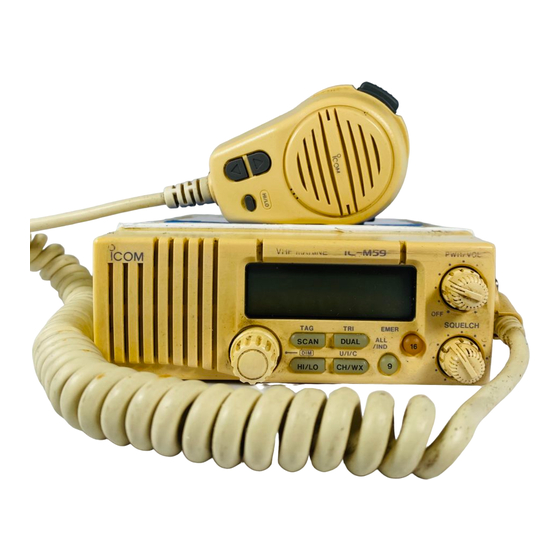
- Page 1 INSTRUCTION MANUAL VHF MARINE TRANSCEIVER iC- m59...
-
Page 2: In Case Of Emergency
IN CASE OF EMERGENCY If your vessel requires assistance, contact other vessels and the Coast Guard by sending a distress call on channel 16. ❍ USING CHANNEL 16 DISTRESS CALL PROCEDURE 1. “MAYDAY MAYDAY MAYDAY” 2. “THIS IS - - - - - - - - - - - - - - ” (name of vessel) 3. -
Page 3: Table Of Contents
TABLE OF CONTENTS IN CASE OF EMERGENCY ...i TABLE OF CONTENTS ... ii IMPORTANT ... iii CAUTIONS... iii 1 OPERATING RULES ... 1 2 PANEL DESCRIPTION ... 2 – 5 I Front panel ... 2 I Microphone ... 3 I Function display ... 4 3 BASIC OPERATION ... -
Page 4: Important
READ ALL INSTRUCTIONS pletely before using the transceiver. SAVE THIS INSTRUCTION MANUAL— struction manual contains important operating instructions for the IC-M59. YOU MUST HAVE a DSC vessel ID in order to oper- ate the optional DSC functions of the transceiver. See your Dealer for details. -
Page 5: Operating Rules
D Priorities • Read all rules and regulations pertaining to priorities and keep an up-to-date copy handy. Safety and distress calls take priority over all others. • You must monitor channel 16 when you are not operating on another channel. •... -
Page 6: Panel Description
PANEL DESCRIPTION I Front panel – CHANNEL SELECTOR [CHANNEL] Selects an operating channel in the selected channel group. — SCAN SWITCH [SCAN• • Starts and stops normal or priority scan when tag chan- nels are programmed. (p. 10) • Push and hold for 1 sec. to toggle the tag setting for the displayed channel. -
Page 7: I Microphone
• Push and hold for 1 sec. to activate tri-watch for checking channel 16 and the call channel. › CALL CHANNEL SWITCH [9• ALL/IND • Selects the call channel—the call channel is programma- ble, channel 9 being the default. (p. 11) •... -
Page 8: I Function Display
PANEL DESCRIPTION I Function display q TRANSMIT INDICATOR Appears while transmitting. (p. 9) w BUSY INDICATOR Appears when receiving a signal or when [SQUELCH] is rotated too far counterclockwise. (p. 8) e CHANNEL INDICATOR Shows the operating channel. (pgs. 6, 7) r TAG CHANNEL INDICATOR Appears when the selected channel is set as a tag chan- nel. -
Page 9: Panel Description ............................................ 2
o DUPLEX INDICATOR Appears when the selected channel is a duplex channel. !0 ACKNOWLEDGEMENT/RECEIVE INDICATORS Appear during optional DSC operation. (pgs. 13–18) • “RCV” appears when a DSC call is received. • “ACK RCV” appears when an acknowledgement is received. •... -
Page 10: Basic Operation
BASIC OPERATION I Power ON ➀ Rotate [PWR/VOL] clockwise to turn power ON. All display indications BUSY TAG DUAL LOW CALL SCAN SCRM appear briefly*. CANUSA DUP ACK RCV *“SCRM” appears only when an optional UT-79 is installed. “dSC” appears only when an optional UX-120 is installed. -
Page 11: Weather Channels
D U.S.A., Canadian and international channels There are 61 U.S.A., 57 Canadian and 57 international chan- nels. These channel groups may be specified for the operat- ing area. ➀ Push [CH/WX] to select a regular channel. • If a weather channel appears, push [CH/WX] again. ➁... -
Page 12: I Receiving
BASIC OPERATION I Receiving ➀ Rotate [PWR/VOL] to turn power ON. ➁ Rotate [SQUELCH] fully counterclockwise. ➂ Adjust [PWR/VOL] to a suitable listening level. ➃ Rotate [SQUELCH] clockwise until the audio noise disap- pears. ➄ Select the desired channel. See pgs. 6–7 for details. •... -
Page 13: I Transmitting
I Transmitting Before transmitting, read the call procedures at right. ➀ Select an operating channel. See pgs. 6, 7 for details. ➁ Push [HI/LO] to select transmit output power. • “LOW” appears when low output power is selected. • High power cannot be selected on some channels. Refer to the channel list on p. -
Page 14: I Scan Function
BASIC OPERATION I Scan function The transceiver has a high speed scan function for standing by on utility signals. The scan speed is 8 channels/sec. (ex- cept when the weather alert function is in use). Two scan types are available: priority scan channels in sequence) and while scanning). -
Page 15: Basic Operation .............................................. 6
I Call channel programming The call channel key, [9], is used to select channel 9, how- ever, you can program your most often-used channels in each channel group for quick recall. ➀ Push [ •U/I/C] for 1 sec. CH/WX one or more times to select the desired channel group (USA, INT, CAN) to be pro- grammed. -
Page 16: Digital Selective Calling
This is used for announcement to all ships in the specified area—when a GPS receiver is Geographical area call connected calls directed to areas other than yours are rejected. Receive only for the IC-M59. In addition, when a GPS receiver (NMEA0183 ver. 1.5, 2.0 or is installed, digital selec- 2.1) is connected, your vessel’s position and the current UTC... -
Page 17: I Distress Call Transmission
I Distress call transmission CAUTION: Distress calls may be transmitted under conditions of emergency only i.e. your vessel is in danger of sinking and/or a person’s life is in danger. ➀ Push and hold [ •EMER] until you hear 4 short beeps change to one long beep. -
Page 18: I All Ships Call Transmission
DIGITAL SELECTIVE CALLING I All ships call transmission Large ships use channel 70 as their “listening channel.” When you want to announce a message to these ships, use the “all ships call” function. ➀ Select a simplex channel for the traffic channel (for voice communication after sending the all ships call). -
Page 19: I Individual Call Transmission
I Individual call transmission The individual call function allows you to transmit a DSC sig- nal to a specific party only. ➀ Set the ID code for the individual you wish to call in ad- vance. • This code is input into the address item in SET mode. (p. 19) ➁... -
Page 20: I Receiving Dsc Calls
DIGITAL SELECTIVE CALLING I Receiving DSC calls Several types of DSC transmissions can be received. The re- quired action depends on the particular DSC type as outlined in the following examples. However, in all examples, you must be monitoring channel 70 in order to receive such signals. NOTE: When channel 70 is set as a tag channel and scan is functioning, DSC calls will not be received. -
Page 21: Receiving An Individual Call
D Receiving a geographical area call While monitoring channel 70 and a geographical area call (for the area you are in) is received: ➥ Emergency alarm or beeps sound depending on the re- ceived category. ➥ “RCV” and “GEO” appear in the display;... -
Page 22: Set Mode
DIGITAL SELECTIVE CALLING • When semi-automatic (SA; default) or manual (SL) is selected in SET mode (p. 21): ➀ Push and hold [9•ALL/IND] until you hear 4 short beeps change into one long beep to send “Able to comply” message. •... -
Page 23: I Entering Set Mode
I Entering SET mode SET mode is used to customize operation of the transceiver to suit your operating needs. D To enter SET mode: ➀ While pushing [16], turn power ON. • Keep pushing [16] until the initial SET mode display appears. •... - Page 24 SET MODE D BEEP TONES This item sets the transceiver's confirmation beep tones (when pushing a switch/rotating [CHANNEL]) ON or OFF. Beep tones ON (default) NOTE: Emergency alarm and beeps for DSC operation cannot be turned OFF. D NORMAL/PRIORITY SCAN This item sets the scan function to normal or priority operation.
- Page 25 D ADDRESS This item sets the other station’s 10-digit ID code for individual calls. Note that your own ID cannot be set in SET mode. ➀ Push [9] to select the digit (1 through 10). ➁ Rotate [CHANNEL] to set the desired value for the selected digit or turn the individual call OFF.
-
Page 26: Connections And Maintenance
CONNECTIONS AND MAINTENANCE I Unpacking q Mounting bracket ... 1 w DC power cable (OPC-632) ... 1 e Microphone hanger (OPC-562) ... 1 r Mounting bracket knobs ... 4 t Mounting screws (5 x 20) ... 4 y Mic hanger screws (3.5 x 30) ... 2 u Flat washers (M4) ... -
Page 27: I Connections
I Connections q DSC CONNECTOR (optional OPC-457; through the UX-120) 7-pin plug connects a GPS receiver for transmission of po- sition data and time. q Test data out + y Test data out _ Acceptable command: GAA Acceptable format: NMEA0183 ver. 1.5, 2.0 or 2.1 CONNECTIONS AND MAINTENANCE w DC POWER CONNECTOR Connects the supplied DC power cable from this connec-... -
Page 28: I Mounting The Transceiver
CONNECTIONS AND MAINTENANCE I Mounting the transceiver The universal mounting bracket supplied with your transceiver allows overhead or dashboard mounting. Please read the fol- lowing instructions carefully. • Mount the transceiver securely with the 4 supplied screws (M5 x 20) to a surface which is more than 10 mm thick and can support more than 5 kg. -
Page 29: I Dimensions
CONNECTIONS AND MAINTENANCE I Dimensions 146 mm 5 ⁄ " 70 mm 2 ⁄ " 54 mm 2 ⁄ " 141 mm 5 ⁄ " 166 mm 5 ⁄ "... -
Page 30: I Antenna
I Optional unit installations In order to add the DSC or voice scrambler functions to the IC-M59, the following optional units must be installed. UX-120: DSC functions OPC-457: GPS connection when UX-120 is installed UT-79: Voice scrambler function ➀... - Page 31 Opening the transceiver case (Fig. 1) Apply 4 to 6 kg torque when replacing screws. UX-120 installation (Fig. 3) Supplied with the UX-120. Be careful not to shift the connector. CONNECTIONS AND MAINTENANCE UT-79 installation (Fig. 2) UT-79 Attach the operating sticker here.
-
Page 32: Troubleshooting
TROUBLESHOOTING PROBLEM No power comes on. No sound comes from the speaker. No beeps sound even when a switch is pushed. Sensitivity is low and only strong signals are audible. Transmitting is impossible or high power cannot be se- lected. Desired channel cannot be selected. -
Page 33: Vhf Marine Channel List
Channel number Frequency (MHz) Channel number Frequency (MHz) CAN Transmit Receive 156.050 160.650 156.050 156.050 156.100 160.700 156.100 156.100 156.150 160.750 156.150 156.150 156.200 160.800 04A 156.200 156.200 156.250 160.850 05A 156.250 156.250 156.300 156.300 156.350 160.950 07A 156.350 156.350 156.400 156.400 156.450 156.450 156.500 156.500... -
Page 34: Specifications
SPECIFICATIONS General • Frequency coverage • Usable channels • Mode • Power supply requirement • Current drain (at 13.8 V DC) • Frequency stability • Usable temp. range • Dimensions (projections not included) • Weight Transmitter : Transmit 156–157.5 MHz •... -
Page 35: Options
MB-28 FLUSH MOUNT SP-5 EXTERNAL For mounting the IC-M59 to a SPEAKER panel. Available in black or A large, external speaker for white. superior audio output. OPC-457 NMEA CABLE Allows you to connect NMEA equipment such as a GPS re- ceiver. - Page 36 Count on us! ➀ A-5384D-1EX- Printed in Japan Copyright © 1996 by Icom Inc. 1-1-32 Kamiminami, Hirano-ku, Osaka 547-0003 Japan...
Need help?
Do you have a question about the IC-M59 and is the answer not in the manual?
Questions and answers