Table of Contents
Advertisement
Quick Links
INSTRUCTION MANUAL
VHF MARINE TRANSCEIVERS
|M410BB
|M510BB
This device complies with Part 15 of the FCC
Rules. Operation is subject to the condition that
this device does not cause harmful interference.
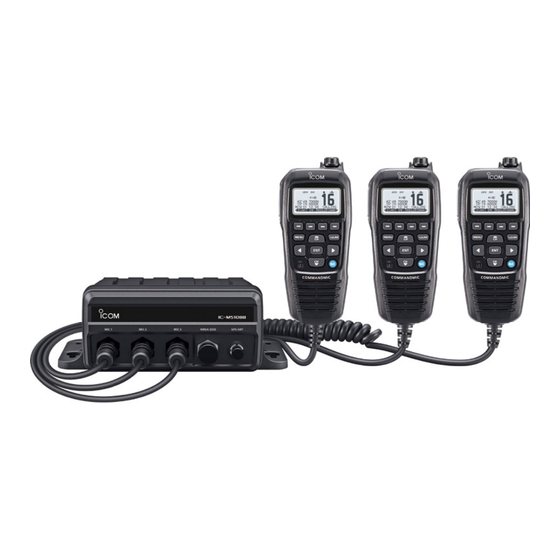
The photo shows the IC-M510BB.
One COMMANDMIC™ comes with the transeciver.
Ihr Partner für Funktechnik
www.fellecs-tech.com
inbox@fellecs-tech.com
Advertisement
Table of Contents

Subscribe to Our Youtube Channel
Related Manuals for Icom IC-M410BB


Summary of Contents for Icom IC-M410BB
- Page 1 INSTRUCTION MANUAL VHF MARINE TRANSCEIVERS |M410BB |M510BB The photo shows the IC-M510BB. One COMMANDMIC™ comes with the transeciver. This device complies with Part 15 of the FCC Rules. Operation is subject to the condition that this device does not cause harmful interference. Ihr Partner für Funktechnik www.fellecs-tech.com inbox@fellecs-tech.com...
-
Page 2: Important
Thank you for choosing this Icom product. This product was designed and built with Icom’s state of the art technology and craftsmanship. With proper care, this product should provide you with years of trouble- free operation. ■ Important ■ Features... -
Page 3: In Case Of Emergency
■ In Case of Emergency If your vessel requires assistance, contact other vessels and the Coast Guard by sending a distress call on Channel 16 or transmit your Distress call using Digital Selective Calling (DSC) on Channel 70. D Using Channel 16 D Using Digital Selective Calling Push [16/C] to switch to Channel 16. -
Page 4: Radio Operation Warning
■ Radio Operation Warning Icom requires the radio operator to meet the FCC Requirements for Radio Frequency Exposure. An omnidirectional antenna with gain not greater than 9 dBi must be mounted a minimum of 5 meters (measured from the lowest point of the antenna) vertically above the main deck and all possible personnel. -
Page 5: Avertissement Pour Les Opérateurs Radio
■ Avertissement Pour Les Opérateurs Radio Icom exige que l’opérateur radio se conforme aux exigences de la FCC en matière d’exposition aux radiofréquences. Une antenne omnidirectionnelle dont le gain ne dépasse pas 9 dBi doit être fixée à une distance minimale de 5 mètres (mesurée depuis le point le plus bas de l’antenne) verticalement au-dessus du pont principal et de tout le... -
Page 6: Fcc Information
• Consult the dealer or an experienced radio/TV technician for help. CAUTION: Changes or modifications to this transceiver, not expressly approved by Icom Inc., could void your authority to operate this transceiver under FCC regulations. ■ Information FCC Cet appareil est conforme à la partie 15 de la réglementation FCC. Son fonctionnement est soumis à... -
Page 7: Note
■ Note CAUTION: DO NOT use harsh solvents such as Benzine or alcohol when cleaning. A WARNING STICKER is supplied with This could damage the equipment the USA version transceiver. surfaces. If the surface becomes dusty or To comply with FCC regulations, this sticker dirty, wipe it clean with a soft, dry cloth. - Page 8 ■ Précautions MISE EN GARDE : La face arrière de la R AVERTISSEMENT ! NE JAMAIS relier l’émetteur-récepteur à une prise CA. Cela VHF chauffe en cas d’utilisation continue pourrait provoquer un choc électrique ou un sur une longue durée. incendie.
-
Page 9: Installation Note
■ About UKCA DOC To obtain the UKCA Declaration of Conformity, please contact Icom UK Limited by email at info@icomuk.co.uk or alternatively call + 44(0) 1227 741741. For the European versions: The following caution is printed on the labels of the transceiver. -
Page 10: Recommendation
The transceiver may lose its waterproof protection if the case or microphone is cracked or broken, the microphone connector is not screwed in completely, or the transceiver has been dropped. Contact your Icom distributor or your dealer for advice. ■ Key Icon Description The keys are described in this manual as follows: The keys that have words or letters on them are described with the characters “[ ].”... -
Page 11: Table Of Contents
■ Table of Contents ■ Important ..........i 1 OPERATING RULES ......1 ■ Explicit Definitions ......i 2 PANEL DESCRIPTION ...... 2 ■ Features ..........i ■ Command microphone ...... 2 ■ In Case of Emergency......ii ■ Function Display (INFO screen) ..3 ■... - Page 12 8 AIS FUNCTION 5 SCAN OPERATION ......14 (For only the IC-M510BB) ....52 ■ Scan types ........14 ■ Setting Favorite channels ■ About AIS ........52 (Except for the NLD version) ... 15 ■ AIS classes ........52 ■...
- Page 13 ■ Specifications ........87 ■ Dimensions ........89 ■ Options ..........90 13 TROUBLESHOOTING ..... 91 14 CHANNEL LIST ........ 93 ■ For IC-M410BB/IC-M510BB USA version ........93 ■ For IC-M410BB/IC-M510BB EUR version ........95 FELLECS-TECH | inbox@fellecs-tech.com | www.fellecs-tech.com...
-
Page 14: Operating Rules
NOTE For the UK version: Even though the IC-M410BB/IC-M510BB is capable of operation on VHF marine channels 1021, 1023, 1081, 1082 and 1083, according to FCC regulations these simplex channels cannot be lawfully used by the general population in USA waters. -
Page 15: Panel Description
PANEL DESCRIPTION ■ Command microphone Front panel: Rear panel: Function display Microphone Speaker 1 PTT SWITCH [PTT] 6 ENTER KEY [ENT] (p. 13) Hold down to transmit, release to receive. Push to set the entered data, selected item, and so on. 2 SOFTWARE KEYS (p. -
Page 16: Function Display (Info Screen)
PANEL DESCRIPTION ■ Function Display (INFO screen) L When you switch the main screen between the INFO, the Plotter, and the MOB screens, push * For only the IC-M510BB. 1 2 34 5 6 7 8 9 10 . 12 20 19... - Page 17 PANEL DESCRIPTION 16 SOFTWARE KEYS (p. 5) 18 POSITION Software key functions are displayed. The current position is displayed when valid GPS data is received, or the 17 TIME ZONE position has been manually entered. The current time is displayed when valid •...
-
Page 18: Software Keys
PANEL DESCRIPTION ■ Software Keys D Software Key functions Various often-used functions are assigned Compose Distress [DTRS] (p. 20) to the Software Keys for easy access. The functions’ icons are displayed above the Push to display the “COMPOSE DISTRESS” Software Keys, as shown below. screen to select the nature of distress, then to make a call. - Page 19 PANEL DESCRIPTION Scan [SCAN] RX Play [PLAY] (p. 14) (p. 67) (Except for the NLD version) (For only the IC-M510BB) Push to start or stop a Normal or Priority Push to play back the recorded audio. scan. RX Hailer [ (p. 69) Dualwatch/Tri-watch [DW]/[TW] (p.
-
Page 20: Preparation
PREPARATION For only the EUR version: When you turn ON the transceiver, “Model” screen is displayed depending on the setting. Select the country where you operate the transceiver. ■ Entering the MMSI code The Maritime Mobile Service Identity (MMSI: DSC self ID) code consists of 9 digits. You can only enter the code when turning ON the transceiver for the first time. -
Page 21: Entering The Atis Id (For The Nld And Frg Versions)
PREPARATION ■ Entering the ATIS ID (For the NLD and FRG versions) The Automatic Transmitter Identification System (ATIS) ID consists of 10 digits. You can enter the ID in the “ATIS ID Input” item on the Menu screen. This ID entering can be done only once. After entering, it can be changed only by your dealer or distributor. -
Page 22: Basic Operations
BASIC OPERATIONS ■ Selecting a channel D Regular Channel You can select a channel by pushing [▲] or [▼]. D Channel 16 Channel 16 is the distress and safety channel. It is used to establish the initial contact with a station, and for emergency communications. Channel 16 is monitored during both Dualwatch and Tri-watch. -
Page 23: Weather Channels And Weather Alert (For Only The Usa Version)
BASIC OPERATIONS ■ Weather channels and Weather Alert (For only the USA version) The USA version transceiver has 10 preset Weather channels. The transceivers are capable* of monitoring broadcasts from the National Oceanographic and Atmospheric Administration (NOAA). The transceiver automatically detects a Weather alert tone on the selected weather channel, or while scanning. -
Page 24: Adjusting The Volume/Squelch/ Backlight/Display Contrast
BASIC OPERATIONS ■ Adjusting the volume/ squelch/backlight/ display contrast D Adjusting the volume level Rotate [VOL] to adjust the audio volume level. D Adjusting the squelch level Squelch enables the audio to be heard only while receiving a signal that is stronger than the set level. -
Page 25: Setting The Call Channel
BASIC OPERATIONS ■ Setting the Call channel By default, a Call channel is set in each Channel Group. You can set your most often-used channel as your Call channel in each Channel Group for quick recall. Open the “CALL CHANNEL” screen. [MENU] >... -
Page 26: Receiving And Transmitting
BASIC OPERATIONS ■ Receiving and transmitting CAUTION: DO NOT transmit without an antenna. Push [▲] or [▼], or push [DIAL] one or more times and rotate [DIAL] to select a channel to call on. • The channel number and name are briefly displayed. is displayed while receiving a signal. -
Page 27: Scan Operation
SCAN OPERATION ■ Scan types You can find ongoing communication by scanning the Favorite channels. Scan is for all the transceiver versions except the NLD version. Before starting a scan : • Set the channels that you want to scan as Favorite channels. (p. 15) L Only the Favorite channels are scanned. -
Page 28: Setting Favorite Channels (Except For The Nld Version)
SCAN OPERATION ■ Setting Favorite channels (Except for the NLD version) You can quickly recall often-used channels by setting them as Favorite channels. You can set Favorite channels in each Channel Group. Select a Channel Group on the Menu screen. (p. 9) [MENU] >... -
Page 29: Dualwatch/Tri-Watch (Except For The Nld Version)
DUALWATCH/TRI-WATCH (Except for the NLD version) ■ Description Dualwatch and Tri-watch are convenient to periodically check Channel 16 while you are operating on another channel. Tri-watch Dualwatch Call channel Operating CH 16 Operating channel channel CH 16 Periodically checks Channel Periodically checks Channel 16 and the Call channel while operating on 16 while operating on another... -
Page 30: Digital Selective Calling (Dsc)
DIGITAL SELECTIVE CALLING (DSC) ■ DSC address ID D Entering an Individual or Group ID You can enter a total of 75 Individual IDs and 25 Group IDs, and assign names to them of up to 10 characters. Open the “INDIVIDUAL ID” or “GROUPID” screen. [MENU] >... -
Page 31: Entering The Position And Time
DIGITAL SELECTIVE CALLING (DSC) D Deleting an entered ID (Example: Deleting an Individual ID: STATION 2) Open the “INDIVIDUAL ID” screen. [MENU] > Settings > DSC > Individual ID Select “STATION 2,” and then push • “Delete the ID. Are You Sure?” is displayed. Push to delete. -
Page 32: Sending Dsc Calls (Distress)
DIGITAL SELECTIVE CALLING (DSC) ■ Sending DSC calls (Distress) A Distress call should be sent if, in the opinion of the captain, the ship or a person is in distress and requires immediate assistance. NEVER MAKE A DISTRESS CALL IF YOUR SHIP OR A PERSON IS NOT IN AN EMERGENCY. - Page 33 DIGITAL SELECTIVE CALLING (DSC) D Regular call Select the nature of the Distress call to include in the Regular Distress call. Push • The “COMPOSE DISTRESS” screen is displayed. Push [ENT] or [DIAL] to enter the Nature selection mode. Select the nature of the Distress, and then push [ENT] or [DIAL].
- Page 34 DIGITAL SELECTIVE CALLING (DSC) D Distress Cancel call If you have accidentally made a Distress call, or made an incorrect Distress call, send a Distress Cancel call to cancel the call as soon as possible while waiting for an Acknowledgment. Be sure to report the purpose of the cancellation. While waiting for an Acknowledgment, push •...
- Page 35 DIGITAL SELECTIVE CALLING (DSC) D Sending a Distress Relay acknowledgment (For only the USA version) You can send the Distress Relay acknowledgment only when a Distress Relay call is received. When a Distress Relay call is received: • An alarm sounds. •...
-
Page 36: Sending Dsc Calls (Other)
DIGITAL SELECTIVE CALLING (DSC) ■ Sending DSC calls (other) NOTE: To ensure proper DSC operation, be sure to correctly adjust the “CH 70 SQL Level” item on the Menu screen. (p. 45) D Sending an Individual call An Individual call enables you to send a DSC signal to only a specific station. You can communicate after receiving the Acknowledgment “Able to comply.”... - Page 37 DIGITAL SELECTIVE CALLING (DSC) When you receive an Acknowledgment “Able to comply”: • An alarm sounds. • The screen on the right is displayed. 10. Push to turn OFF the alarm. • The channel assigned in step 7 is automatically selected. L If the called station cannot use the channel that you assigned, a different channel is selected by the other station.
- Page 38 DIGITAL SELECTIVE CALLING (DSC) D Sending an All Ships call All Ships that have DSC transceiver use Channel 70 as their listening channel. When you want to announce a message to these ships, if they are within range, use the All Ships call.
- Page 39 DIGITAL SELECTIVE CALLING (DSC) D Sending a Group call A Group call enables you to send a DSC call to only a specific group. L You can send a Group call to a pre-entered group address, or manually enter the address before sending.
- Page 40 DIGITAL SELECTIVE CALLING (DSC) D Sending a Test call You should avoid testing calls on the exclusive DSC Distress channels and safety calling channels. When you cannot avoid testing on a Distress or safety channel, you should indicate that these are test calls. Normally the Test call would require no further communications between the two stations involved.
- Page 41 DIGITAL SELECTIVE CALLING (DSC) D Sending a Test Acknowledgment By default, when you receive a Test call, the Auto ACK function automatically sends an Acknowledgment to the calling station (p. 44). If the function is set to “Manual,” do the following steps to send an Acknowledgment.
- Page 42 DIGITAL SELECTIVE CALLING (DSC) D Sending a Position Request call/Polling Request call* (* For only the USA version) You can send a Position Request call or Polling request call to a station, depending on the presetting. • Send a Position Request call when you want to know a specific ship’s current position. •...
- Page 43 DIGITAL SELECTIVE CALLING (DSC) D Sending a Position Reply call Send a Position Reply call when a Position Request call is received. If the Auto ACK function is set to “Auto,” the Acknowledgment is automatically sent to the calling station. (p. 44) After a Position Request is being received, push to turn OFF the alarm.
- Page 44 DIGITAL SELECTIVE CALLING (DSC) D Sending a Position Reply call Accepts the call. • Displays the received call’s information. • The call is saved in the DSC Log. Push , then push to send the Position Reply call. Closes the call, and then returns to the operating screen.
- Page 45 DIGITAL SELECTIVE CALLING (DSC) D Sending a Polling Reply call Send a Polling Reply call when a Polling Request call is received. L When “Polling ACK” is set to “Auto,” the transceiver automatically sends the call. While a Polling Request call is being received, push to turn OFF the alarm.
-
Page 46: Receiving Dsc Calls (Distress)
DIGITAL SELECTIVE CALLING (DSC) ■ Receiving DSC calls (Distress) The transceiver receives Distress calls, Distress Acknowledgments, and Distress Cancel calls. When you receive a call, an emergency alarm sounds. NOTE: The screens that are displayed when a Distress call or an Acknowledgment is received slightly differ from one another. - Page 47 DIGITAL SELECTIVE CALLING (DSC) When a Distress acknowledgment is received: After a Distress Acknowledgments is being received, push to turn OFF the alarm. Push . • The received information is displayed. Push • The received information is displayed. Push • “Terminate the procedure. Are you sure?” is displayed.
- Page 48 DIGITAL SELECTIVE CALLING (DSC) D Receiving a Distress Relay call When a Distress Relay call is received: • An alarm sounds. • The following screen is displayed and the backlight blinks. • “ ” blinks. Push Push the Software Key below the next operation.
-
Page 49: Receiving Dsc Calls (Other)
DIGITAL SELECTIVE CALLING (DSC) ■ Receiving DSC calls (other) The transceiver receives the following types of DSC calls. • Individual call • Polling Request call (p. 32) • Individual Acknowledgment (p. 24) • Test call (p. 39) • Group call / All Ships call (p. 37) •... - Page 50 DIGITAL SELECTIVE CALLING (DSC) D Receiving a Group call or All Ships call When a Group call is received: ( Example: • An alarm sounds. when a Group call is received) • “RECEIVED GROUP CALL” is displayed. When an All Ships call is received: •...
- Page 51 DIGITAL SELECTIVE CALLING (DSC) D Receiving a Position Request call (May not be used, depending on the presetting) NOTE: Even if the Auto ACK function is set to “Manual” while waiting to receiving a distress acknowledgment or after receiving a distress acknowledgment, the Position Reply is automatically sent to the calling station.
- Page 52 DIGITAL SELECTIVE CALLING (DSC) D Receiving a Test call When a Test call is received: • An alarm sounds. • “RECEIVED TEST CALL” is displayed. Push to turn OFF the alarm. Push the Software Key below your next operation. : Ignores the call and returns to the operating screen.
- Page 53 DIGITAL SELECTIVE CALLING (DSC) D Receiving a Test acknowledgment/Position Reply call /Polling Reply call Example: Receiving a Test acknowledgment When a call is received: • An alarm sounds. • The following screen is displayed and the backlight blinks. • “ ”...
-
Page 54: Dsc Log
DIGITAL SELECTIVE CALLING (DSC) ■ DSC Log D Received DSC Log The transceiver saves up to 50 received Distress call messages and 50 received “Others” call messages in your DSC Log. On the operating screen, “ ” is displayed when there is an unread call message. The icon blinks when there is a new received call message. -
Page 55: Multiple-Task Mode
DIGITAL SELECTIVE CALLING (DSC) ■ Multiple-task mode (For only the USA version, depending on the presetting) If the Multiple-task function is enabled, the transceiver can hold up to 7 tasks. You can handle more than 2 DSC tasks simultaneously by switching between the tasks. To use the Multiple-task mode, select “Multiple”... - Page 56 DIGITAL SELECTIVE CALLING (DSC) D Task list You can display the “TASK LIST” screen by pushing The number of tasks is displayed at the top of the screen. The number of tasks On the “TASK LIST” screen, the following Software Keys are displayed. Holds the task and returns to the operating screen.
-
Page 57: Dsc Settings
DIGITAL SELECTIVE CALLING (DSC) ■ DSC Settings CH Auto Switch Select whether or not to automatically On the “DSC” screen, you can make switch to channel 16 or the specified settings of the DSC call related items. channel, or ignore the call. [MENU] >... - Page 58 DIGITAL SELECTIVE CALLING (DSC) ■ DSC Settings Alarm Status Self Check Test Sets the alarm ON or OFF when receiving The Self-Test sends DSC signals to the each type of DSC call. receiving AF circuit to compare the sending z Safety and receiving signals at the AF level.
-
Page 59: Making An Individual Call To An Ais Target
DIGITAL SELECTIVE CALLING (DSC) ■ Making an Individual call to an AIS target You can transmit an Individual call to a selected AIS target, without entering the target’s MMSI code. In this case, the call type is automatically set to Routine. D Selecting an AIS target on the IC-M510BB You can compose an Individual call to an AIS target selected on the Plotter screen or the AIS list. - Page 60 DIGITAL SELECTIVE CALLING (DSC) D Using an AIS transponder Transponder operation: Select an AIS target on the plotter display, Target, Danger, or Friends list screen. L See the MA-510TR INSTRUCTION MANUAL for details. Push [ENT] to display the Menu window. •...
- Page 61 DIGITAL SELECTIVE CALLING (DSC) Transceiver operation: When the acknowledgment is received, alarm sounds. z If the acknowledgment ‘Able to comply’ is received, push to stop the alarm, and then select the voice channel specified in step 4. • A different voice channel will be selected if the station you called cannot use the channel.
-
Page 62: Dsc Remote Control (En 300 338-8 Compatible)
With controllers connected to the transceiver, you can perform DSC remote control communications. Up to 2 command microphones can be used with the IC-M410BB, and up to 3 command microphones and an external device can be used as controllers with the IC-M510BB. - Page 63 DIGITAL SELECTIVE CALLING (DSC) D Dealing with ID and Priority When controllers are connected to the transceiver, the unique ID is automatically assigned to each controller in order from 1 to 99. Once a controller is set as the Priority Controller, however, its ID is replaced with 0 because the ID of the Priority Controller ID is fixed at 0.
- Page 64 DIGITAL SELECTIVE CALLING (DSC) D Allowing controllers to perform DSC operations Select whether or not to allow controllers to perform DSC operations. Open the “DSC OPERATION” screen. [MENU] > Settings > Configuration > Controller > DSC Operation L Only controllers connected to the transceiver are listed.
-
Page 65: Ais Function (For Only The Ic-M510Bb)
AIS FUNCTION (For only the IC-M510BB) NOTE: The IC-M510BB can be input AIS information from the built-in AIS receiver or an external NMEA 0183 or NMEA 2000 sentence source. ■ About AIS The Automatic Identification System (AIS) is primarily used for collision-risk management and navigation safety. -
Page 66: Using The Plotter Screen
AIS FUNCTION ■ Using the Plotter screen On the plotter screen, the display range, the icons of the AIS target, and MOB are displayed. You can change the display range and type, depending on your operating style. Push and then select “Plotter”. •... - Page 67 AIS FUNCTION D Plotter screen 3 TARGET ICONS Targets whose AIS signal are received Displays the plotter display and selected are displayed with icons. The icon may target’s information. differ, depending on the target type or its status. Icon Description AIS target: Vessel AIS target: Search and Rescue (SAR) vessel...
- Page 68 AIS FUNCTION D Plotter screen Displayed when the type of targets on the plotter screen are filtered. (p. 61) [MENU] > Settings > AIS > Target Display All Targets: All AIS targets are displayed. Danger Only: Only Danger AIS targets are displayed.
-
Page 69: Using The Ais List Screen
AIS FUNCTION ■ Using the AIS list screen There are 3 types of AIS lists, Target, Danger, and Friends. The target’s information is automatically updated every 5 seconds, and then the AIS target data is sorted. Push [MENU]. • The Menu screen is displayed. Push [▲], [▼], or rotate [DIAL] to select “AIS,”... - Page 70 AIS FUNCTION D Target/Friends List screen D Danger list screen The Target List screen displays up to 200 The Danger List screen displays any AIS targets. Danger target whose CPA (Closest Point The Friends List screen displays the AIS of Approach) distance and TCPA (Time to targets of up to 100 targets that you set as CPA) time are less than the set values.
-
Page 71: Setting A Friend
AIS FUNCTION ■ Setting a Friend You can set up to 100 AIS targets as a Friend in the Friends List. An alarm sounds when a Friend is detected, depending on the setting. (p. 62) D Entering an ID Selecting on the plotter display: Open the plotter screen. -
Page 72: About The Detail Screen
AIS FUNCTION ■ About the Detail screen The Detail screen displays the information about the selected AIS target. The contents may differ, depending on the selected target. L When a Danger target is selected, is displayed.(p. 57) L When a Friend target is selected, is displayed. - Page 73 AIS FUNCTION PA (Position Accuracy (H: High, L: Low)) Position (Latitude, Longitude) Range SOG (Speed Over Ground) Bearing COG (Course Over Ground) Bow to antenna distance ALT (Altitude) Stern to antenna distance PA (Position Accuracy (H: High, L: Low)) Port side to antenna distance Range Starboard side to antenna distance Bearing...
-
Page 74: Ais Settings
AIS FUNCTION ■ AIS settings AIS settings can be customized in “AIS” on the Menu screen. [MENU] > Settings > AIS North up/Course up CPA/TCPA z Alarm You can select the display type for the plotter screen. You can select whether or not to turn the North up: The top of the plotter screen following alarm functions ON or OFF. - Page 75 AIS FUNCTION Friends z Slow Warn The GPS receiver calculated COG data z Friends List of a vessel that is at anchor or drifting Displays all Friend targets that you have is unreliable, and therefore the CPA entered. and TCPA data may not be calculated L “No ID”...
- Page 76 AIS FUNCTION ■ AIS settings ID Blocking The transceiver blocks AIS transponders that are entered into the ID Blocking list. Enter your vessel’s transponder ID or other vessel’s transponder IDs if necessary to prevent the transceiver from detecting them as dangerous targets. L You can enter up to 10 MMSI codes.
-
Page 77: Other Functions
OTHER FUNCTIONS NOTE: For the other functions, the transceiver must be receiving valid GPS signals, or your position must be entered. (p. 18) ■ MOB (Man Overboard) (For only the IC-M510BB) You can enter a Man OverBoard (MOB) waypoint into the transceiver with its GPS position data, as soon as a person has fallen into the water and needs to be rescued. -
Page 78: Anchor Watch (For Only The Ic-M510Bb)
OTHER FUNCTIONS ■ Anchor Watch (For only the IC-M510BB) Anchor Watch is the function to sound an alarm when your vessel is at anchor and has drifted. D Starting Anchor Watch z Push to start the Anchor Watch mode. • The “ANCHOR INFORMATION” screen is displayed. -
Page 79: Lost Target (For Only The Ic-M510Bb)
OTHER FUNCTIONS ■ Lost target (For only the IC-M510BB) A vessel is regarded as a “Lost target” after a specified period of time has passed since the vessel last transmitted data, as described below. The “Lost target” icon disappears from the plotter display 6 minutes and 40 seconds after the vessel was regarded as a “Lost target.”... -
Page 80: Voice Record (For Only The Ic-M510Bb)
OTHER FUNCTIONS ■ Voice Record (For only the IC-M510BB) This function automatically records the last 120 seconds of the received audio. D Audio recording Open the “VOICE RECORD” screen. [MENU] > Settings > Radio > Voice Record Select “Auto (Last 120 sec).” z Recording starts automatically when a signal is received. -
Page 81: Using The Intercom
The Intercom function enables you to communicate between the deck and the cabin. The optional HM-195 commandmic is required for Intercom operation. ™ The IC-M410BB only supports one-to-one intercom, while the IC-M510BB also supports one-to-many intercom. L Connect the HM-195 as described on page 85. NOTE: While using the Intercom function, •... -
Page 82: Using The Rx Hailer
OTHER FUNCTIONS ■ Using the RX Hailer The RX Hailer function enables you to hear the received audio on the deck or bridge through a Hailer speaker. To use this function, the external hailer speaker must be connected to the transceiver. L See page 82 for details of the connection. -
Page 83: Using The Hailer
OTHER FUNCTIONS ■ Using the Hailer You can talk without leaving the bridge by using the 1 way hailer function. To use this function, the external hailer speaker must be connected to the transceiver. • You cannot transmit while using the hailer. Open the “Hailer”... -
Page 84: Using The Horn Function
OTHER FUNCTIONS ■ Using the Horn function D Automatic Foghorn function The Automatic Foghorn function sounds a horn repeatedly until the function is turned OFF. The foghorn outputs from the hailer speaker. To use this function, the hailer speaker must be connected to the transceiver. - Page 85 OTHER FUNCTIONS D Horn Volume function Open the “HORN VOLUME” screen. [MENU] > Horn > Horn Volume Push [◄] or [►], or rotate [DIAL] to adjust the foghorn level. D Manual Horn function Open the “MANUAL HORN” screen. [MENU] > Horn > Manual Horn Hold down to sound a horn.
-
Page 86: Menu Screen
MENU SCREEN ■ Using the Menu screen The Menu screen is used to set items, select options, and so on for the transceiver’s functions. D Menu screen operation Example: Setting the key beep to “OFF.” Push [MENU]. • The Menu screen is displayed. Push [▲] or [▼], or rotate [DIAL] to select “Settings,”... - Page 87 MENU SCREEN D Menu screen items The Menu screen contains the following items. See the referred pages for each items. The displayed menu items may differ, depending on the transceiver version or presetting. Menu Submenu Item Reference – Nature p. 19 Compose Distress Position...
- Page 88 MENU SCREEN D Menu screen items Menu Submenu Item Reference Backlight p. 11 Display Contrast p. 11 Key Beep p. 76 Key Assignment p. 76 UTC Offset p. 76 Inactivity Timer p. 76 Configuration COMMANDMIC SP p. 77 RX Hailer p.
-
Page 89: Menu Items Description
MENU SCREEN Menu Submenu Item Reference Radio Information – – p. 80 ATIS ID INPUT * – – p. 8 ■ Menu items description D GPS Information UTC Offset Set the offset time between Universal Time Displays your position, date, time, Coordinated (UTC) and your local time to Speed Over Ground (SOG), and Course between –14:00 and +14:00 (in 1 minute steps). - Page 90 MENU SCREEN D Settings COMMANDMIC SP Power Switch Select the speaker to be used. Select whether or not to turn OFF the transceiver at the same time that you turn z Internal Speaker OFF the command microphone. Outputs audio from a command microphone’s speaker.
- Page 91 MENU SCREEN • Radio Channel Group Select the suitable channel group for your [MENU] > Settings > Radio operating area. Select USA, INT, or CAN, Scan Type depending on the transceiver version. (Except for the NLD version) L See page 9 for details. Selects the scan type.
- Page 92 MENU SCREEN D Settings NMEA 2000 • Radio NMEA 2000 is a communication standard [MENU] > Settings > Radio used to connect various marine devices and display units in the vessel. Channel Display The transceiver can easily connect to a You can select the number of digits to NMEA 2000 network with its plug-and-play display the channel number.
- Page 93 MENU SCREEN Compatible PGN list Receive Transmit 059392 ISO Acknowledgment 059392 ISO Acknowledgment 059904 ISO Request 059904 ISO Request 060160 ISO Transport Protocol, Data 060416 ISO Transport Protocol, Transfer Connection Management 060416 ISO Transport Protocol, 060928 ISO Address Claim Connection Management 126208 NMEA - Acknowledge Group 060928 ISO Address Claim...
-
Page 94: Connections
CONNECTIONS ■ Connections L The IC-M510BB is used as an example. Front panel: Rear panel: 1 COMMAND MICROPHONE JACK 5 NMEA IN/OUT LEADS Connects the supplied or optional Yellow: Listener A (Data-H), Data In (+) command microphone. Green: Listener B (Data-L), Data In (–) L Only the IC-M510BB has [MIC3] jack. -
Page 95: Cleaning
CONNECTIONS 6 AF OUT LEADS The pin layout is shown in the figure below. Connects to an external speaker. Orange: External Speaker (+) Gray: External Speaker (–) DSC Remote Out DSC Remote In L Both black and blue leads are used only Talker A (Data-H) Listener A (Data-H) for maintenance purpose. -
Page 96: Supplied Accessories
Self-tapping screws GPS antenna and double-sided adhesive pad Warning sticker (5 × 20 mm) (Except for the IC-M410BB USA version) (For only the USA version) Spring washers (M5) For Command microphone Flat washers (M5) Connector cap... -
Page 97: Mounting The Transceiver
10 mm (0.03 ft) thick and can support more than 5 kg (11 lb) using the 4 supplied screws (5 × 20 mm), as illustrated below. L The same template can be used for both the IC-M410BB and the IC-M510BB, although the IC-M510BB is used as an example below. -
Page 98: Microphone Installation
CONNECTIONS ■ Microphone installation When you use the supplied or optional HM-195 command microphone, the optional 6 meters long OPC-1541 extension cable can be connected between the OPC-1540 and the transceiver to operate from even longer distances. You can also install the extension cable’s connector as a built-in plug on a cabinet or wall. NOTE: The firmware of the command microphones may be updated when you connect them to the transceiver. - Page 99 CONNECTIONS 50 (d) (1 28 (d) (1 29.5 to 31.5 (d) to 1 unit: mm (inch) FELLECS-TECH | inbox@fellecs-tech.com | www.fellecs-tech.com...
-
Page 100: Specifications And Options
SPECIFICATIONS AND OPTIONS ■ Specifications IC-M410BB/IC-M510BB USA Version D General • Frequency coverage: 156.025 ~ 157.425 MHz 156.050 ~ 163.275 MHz DSC (CH70) 156.525 MHz AIS (CH A/B)* 161.975 MHz/162.025 MHz • Mode: 16K0G3E (FM), 16K0G2B (DSC), 16K0GXW (AIS)* • Operating temperature range: –20°C ~ +60°C, –4ºF ~ +140ºF... - Page 101 SPECIFICATIONS AND OPTIONS IC-M410BB/IC-M510BB EUR Version D General • Frequency coverage: 156.025 ~ 161.425 MHz 156.050 ~ 162.000 MHz DSC (CH70) 156.525 MHz AIS (CH A/B)* 161.975 MHz/162.025 MHz • Mode: 16K0G3E (FM), 16K0G2B (DSC), 16K0G2B (AIS)* • Operating temperature range: –20°C ~ +60°C...
-
Page 102: Dimensions
• Load Equivalency Number: L All stated specifications are subject to change without notice or obligation. ■ Dimensions Both the IC-M410BB and the IC-M510BB have the same dimensions. L The IC-M510BB is used as an example. 190 (7.5) 216 (8.5) 8.8 (0.3) -
Page 103: Options
OPC-1541 can be connected. Usable length is 18 meters (60 feet) maximum. • SP-37 horn speaker The external horn speaker. Connect with the AF Out leads for the external speaker. L SP-37 has not been tested and Icom does not guarantee its waterproofness. • UX-241 gnss antenna To receive GPS signals. -
Page 104: Troubleshooting
TROUBLESHOOTING The transceiver does not turn ON. z There is a bad connection to the power supply. → Check the connection to the transceiver and power supply. (p. 82) z The fuse is blown. → Repair the problem, and then replace the fuse. (p. 83) Little or no sound comes from the speaker. - Page 105 TROUBLESHOOTING The transceiver is locked up, and does not respond. z A software error has occurred. → Turn OFF the transceiver, and then turn it ON again. The transceiver does not work. z The transceiver’s Phase Lock Loop is unlocked. →...
-
Page 106: Channel List
CHANNEL LIST ■ For IC-M410BB/IC-M510BB USA version NOTE: When the “Channel Display” is set to “3 digits” in the Radio setting, the channel number is displayed in 3 digits. See page 79 for details. (For example: “1001” is displayed as “01A.”) - Page 107 CHANNEL LIST *1 Low power only. Frequency (MHz) Channel Number *2 RX only. Transmit Receive *3 Momentary High Power. 1028 157.400 157.400 RX only 2028 162.000 156.025 160.625 156.075 160.675 1061 156.075 156.075 156.125 160.725 1062 156.125 156.125 156.175 160.775 1063 1063 1063...
-
Page 108: For Ic-M410Bb/Ic-M510Bb Eur Version
CHANNEL LIST ■ For IC-M410BB/IC-M510BB EUR version NOTE: When the “Channel Display” is set to “3 digits” in the Radio setting, the channel number is displayed in 3 digits. See page 79 for details. (For example: “1001” is displayed as “01A.”) - Page 109 INDEX Accessories Call channel Detail screen....59 Distress call Command Microphone Radio settings ..78 ......2 Selecting ....9 Cancel call ....21 Supplied Setting .....12 Receiving ....33 accessories ..83 CH 70 SQL Level, DSC Regular call .....22 Settings ....45 Sending ....19 About AIS ....52 Channel Simple call ....19 AIS classes .....52...
- Page 110 INDEX Favorite CH ID Blocking MA-510TR Deleting ....63 Connecting ....82 Radio Settings ..78 Favorite channels ..15 Editing .....63 Man Overboard (MOB) Friend Inactivity Timer Starting ....64 Alarm .......62 Configuration ...76 Stopping ....64 Deleting ....58 Individual Acknowledgment Menu screen Editing .....58 Sending ....24 Description ....76 Entering ....58...
- Page 111 INDEX Options ......90 Radio Info ....80 Target Display ....61 Test Acknowledgement Receiving .....13 RX Hailer .....69 Receiving ....40 Panel Description ..2 Configuration ...77 Sending ....28 Plotter Test call Description ....53 Receiving ....39 Use ......53 Scan Sending ....27 Polling Priority .....14 Time, entering ....18 Reply call, receiving 40 Starting ....15...
- Page 112 How the World Communicates Ihr Partner für Funktechnik www.fellecs-tech.com inbox@fellecs-tech.com A7732D-1EX-1 1-1-32 Kamiminami, Hirano-ku, Printed in Japan Osaka 547-0003, Japan © 2023 Icom Inc. Apr. 2023...
Need help?
Do you have a question about the IC-M410BB and is the answer not in the manual?
Questions and answers