Table of Contents
Advertisement
Advertisement
Table of Contents

Related Manuals for Icom IC-M503


Summary of Contents for Icom IC-M503
- Page 1 INSTRUCTION MANUAL VHF MARINE TRANSCEIVER iM503...
-
Page 2: In Case Of Emergency
This warning symbol indicates that this equipment operates in Versions of the IC-M503 which display the “CE” symbol on non-harmonised frequency bands and/or may be subject to licensing the serial number seal, comply with the essential requirements of the conditions in the country of use. -
Page 3: Table Of Contents
TABLE OF CONTENTS I Setting tag channels ...... 36 IN CASE OF EMERGENCY ......i 8 CONNECTIONS AND I Dualwatch/Tri-watch operation ..36 TABLE OF CONTENTS ......ii MAINTENANCE ......18 – 24 I Set mode programming ....37 I Unpacking ........18 IMPORTANT ..........iii I Intercom operation ...... -
Page 4: Important
SAVE THIS INSTRUCTION MANUAL — carefully and completely This in- before using the transceiver. struction manual contains important operating instructions for the IC-M503. CAUTIONS RWARNING! NEVER atures below –20°C or above +60°C or, in areas subject to di- connect the transceiver to an AC rect sunlight, such as the cockpit. -
Page 5: Operating Rules
OPERATING RULES (2) OPERATOR’S LICENSE ï ï PRIORITIES A Restricted Radiotelephone Operator Permit is the license • Read all rules and regulations pertaining to priorities and most often held by small ship radio operators when a radio keep an up-to-date copy handy. Safety and distress calls is not required for safety purposes. -
Page 6: Panel Description
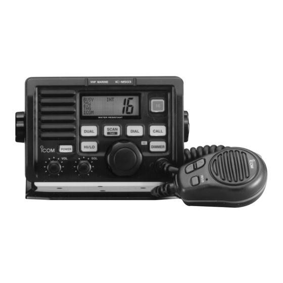
PANEL DESCRIPTION I Panel description iM503 VHF MARINE Function display WATER RESISTANT Speaker SCAN DUAL DIAL CALL HI/LO DIMMER POWER q POWER SWITCH [POWER] r TRANSMIT POWER SWITCH [HI/LO] ➥ Push to Toggle high and low power . (p. 8) Push to toggle the transceiver power ON and OFF. - Page 7 PANEL DESCRIPTION t CHANNEL SELECTOR [CHANNEL] function is not available. !0 SCAN SWITCH [SCAN/TAG] (p. 13) Rotate [CHANNEL] to select the operating channels, set ➥ When tag channels are programmed, starts and stops mode contents, etc. (p. 8) normal or priority scan. ➥...
-
Page 8: I Function Display
10 V DC or below. ➥ “DUAL” appears during dualwatch; “TRI” appears dur- ing tri-watch. (p. 11) ➥ “WAIT” appears in the IC-M503 display while transmit- ting via the HM-134 remote-control microphone. • In the above case, the connected HM-134 has priority. -
Page 9: I Microphone
PANEL DESCRIPTION I Microphone Speaker Microphone q PTT SWITCH [PTT] Push and hold to transmit; release to receive. (p. 8) w CHANNEL UP/DOWN SWITCHES [Y Y ]/[Z Z ] Push either switch to change the operating memory chan- nel, set mode contents, etc. (p. 8) e TRANSMIT POWER SWITCH [HI/LO] ➥... -
Page 10: Basic Operation
16 is selected. For example, when selecting Channel 16 via the ï ï International channels dial, a scan stops at Channel 16 or [16•C] on the HM-134 is There are 57 International channels for the IC-M503. pushed, etc. ➥ Push [DIAL] to return to the condition before selecting Chan- q Push [DIAL] to select a regular channel. - Page 11 BASIC OPERATION ï ï U.S.A. channels (U.K. version only) For the U.K. versions, there are 58 U.S.A. channels in addi- tion to 57 International channels. q Push [DIAL] to select a regular channel. w While pushing and holding [HI/LO], push [DIAL] to change ï...
-
Page 12: I Receiving And Transmitting
BASIC OPERATION I Receiving and transmitting y Push and hold [PTT] to transmit, then speak into the mi- crophone. CAUTION: • “TX” appears. Transmitting without an antenna may dam- • Channel 70 cannot be used for transmission (for GMDSS use). age the transceiver. -
Page 13: I Call Channel Programming
BASIC OPERATION I Call channel programming I Channel names The call channel switch can be programmed to your most Memory channels can be tagged with alphanumeric names often-used channels in each channel group for quick recall. of up to 10 characters each. q While pushing and holding [HI/LO], push [DIAL] one or Capital letters, small letters, numerals, some symbols (! "... -
Page 14: I Optional Voice Scrambler Operation
BASIC OPERATION I Optional voice scrambler operation ï ï Activating the scrambler ï ï Programming scrambler codes The optional voice scrambler provides private communica- There are 128 or 32 codes (0 to 127 or 1 to 32) available for tions. In order to receive or send scrambled transmissions programming. -
Page 15: Dualwatch/Tri-Watch
DUALWATCH/TRI-WATCH I Description I Operation q Select the desired operating channel. Dualwatch monitors Channel 16 while you are receiving an- w Select dualwatch or tri-watch in set mode. (p. 15) other channel; tri-watch monitors Channel 16 and the call e Push [DUAL] to start dualwatch or tri-watch. channel while receiving another channel. -
Page 16: Scan Operations
SCAN OPERATIONS I Scan types Scanning is an efficient way to locate signals quickly over a Set the tag channels (scanned channel) before scanning. wide frequency range. The transceiver has priority scan and Clear the tag channels which inconveniently stop scanning, normal scan. -
Page 17: I Setting Tag Channels
SCAN OPERATION I Setting tag channels for 3 sec. to clear all tag channels in the channel group. I Starting a scan For more efficient scanning, add desired channels as tag channels or clear tag channels that are unwanted channels. Set scan type (priority or normal scan) and scan resume timer Channels set as non-tag channels will be skipped during in advance using set mode. -
Page 18: Set Mode
SET MODE I Set mode programming q Turn power OFF. Set mode is used to change the conditions of the trans- w While pushing and holding [16], turn power ON to enter set ceiver’s functions: scan mode (normal or priority), scan re- sume timer, dualwatch/tri-watch selection, beep tone function mode. -
Page 19: I Set Mode Items
5 sec. and resumes even if a signal is being received on channels, except for Channel 16. Beep tone ON (default) Beep tone OFF *Beep tones setting are selectable on IC-M503 and HM-134 inde- Scan timer ON (default) Scan timer OFF pendently... -
Page 20: Set Mode
ï ï ATIS check LCD contrast 4 (default) The ATIS ID code can be checked in set mode. *LCD contrast setting is adjustable on IC-M503 and HM-134 in- dependently ï ï Scrambler code When an optional scrambler unit is connected, the scrambler ATIS code code can be set depending on dealer setting. -
Page 21: Intercom Operation
INTERCOM OPERATION I Intercom operation • To adjust the IC-M503’s speaker output level, rotate [VOL]. The optional intercom function allows you to talk to the deck • To adjust the HM-134’s speaker output level, push [Y]/[Z] after from the cabin. The optional HM-134*... -
Page 22: Connections And Maintenance
CONNECTIONS AND MAINTENANCE I Unpacking I Antenna The following accessories are supplied: Qty. A key element in the performance of any communication sys- q Mounting bracket ............1 tem is an antenna. Ask your dealer about antennas and the w DC power cable (OPC-891) ........... 1 best places to mount them. -
Page 23: I Connections
CONNECTIONS AND MAINTENANCE I Connections w EXTENSION JACK Connects to the optional DS-100 (#02) DSC CONTROLLER e EXTERNAL MICROPHONE CONNECTOR Connects to the optional HM-134 REMOTE CONTROL MICRO PHONE • Intercom function is available. CAUTION: NEVER connect another microphone such as the HM-127, etc. -
Page 24: I Microphone Hanger
CONNECTIONS AND MAINTENANCE I Microphone hanger OPC-1096 Rest the supplied microphone on the hanger when not in use. Connect the OPC-1096* to the transceivers chassis and mi- crophone hanger to use the microphone hanger function. * Depending on version. • Tighten the screw at fixing torque 0.7 N •m (6.9 kg•m). •... -
Page 25: I Mounting The Transceiver
CONNECTIONS AND MAINTENANCE I Mounting the transceiver • OVERHEAD MOUNTING ï ï Using the supplied mounting bracket The universal mounting bracket supplied with your transceiver allows overhead or dashboard mounting. • Mount the transceiver securely with the 2 screws supplied (M5 ×... - Page 26 Connect the antenna and control cable, then return the in- strument control panel to its original place. e Attach the 2 bolts supplied (M5 × 8 mm) on either side of the IC-M503.
-
Page 27: I Optional Unit Installation
CONNECTIONS AND MAINTENANCE I Optional unit installation CAUTION: w Remove the 4 screws from the shielding plate, then lift up DISCONNECT the DC power cable from the transceiver before performing any work on the transceiver. the shielding plate. e Plug an optional unit to the MAIN unit as shown below. Otherwise, there is danger of electric shock and/or equip- ment damage. -
Page 28: I Dimensions
CONNECTIONS AND MAINTENANCE I Dimensions 145.0 (5 ⁄ ˝) 31.4 53.0 165.0 (6 ⁄ ˝) ˝) ˝) Unit: mm (inch) -
Page 29: Troubleshooting
TROUBLESHOOTING PROBLEM POSSIBLE CAUSE SOLUTION REF. No power comes ON. • Bad connection to the power supply. • Check the connection to the transceiver. p. 19 No sound comes from • Squelch level is too deep. • Set squelch to the threshold point. p. -
Page 30: Channel List
CHANNEL LIST • International channels Frequency (MHz) Frequency (MHz) Frequency (MHz) Frequency (MHz) Frequency (MHz) Frequency (MHz) Transmit Receive Transmit Receive Transmit Receive Transmit Receive Transmit Receive Transmit Receive 156.050 160.650 156.550 156.550 157.050 161.650 156.125 160.725 156.625 156.625 157.125 161.725 156.100 160.700... -
Page 31: Specifications And Options
HM-134. Up to 2 OPC-999 can be connected. (18 m; 60 feet • Output power : 25 W and 1 W maximum) • Modulation system : Variable reactance phase • SP-5 (IC-M503 modulation EXTERNAL SPEAKER ONLY • Max. frequency deviation : ±5.0 kHz A large, external speaker for superior audio output. -
Page 32: Hm-134 Remote-Control Microphone
I Panel description q POWER SWITCH [PWR] (pgs. 8, 33) When the IC-M503 power is turned ON, push and hold for 2 sec. to turn the HM-134 power ON or OFF. The optional HM-134 remotely controls the IC-M503 and pro- vides an optional intercom function. - Page 33 ON. (p. 34) • “ T ” flashes while the all key lock function is in use. IC-M503 in intercom mode. (pgs. 17, 38) • Only [PWR] and [PTT] function when the all key lock function u SQUELCH/MONITOR/LOCK SWITCH [SQL•MONI•L]...
-
Page 34: I Function Display
HM-134 REMOTE-CONTROL MICROPHONE I Function display !1 EXTERNAL SPEAKER JACK ➥ Connect the external speaker ( an 8 Ω load) . The internal speaker can be deactivated via the Set mode program- !6 !5 ming. (p. 37) • The speaker output employs a BTL (Balanced Trans- Less) circuit, NEVER connect the speaker cable to WAIT TX BUSY... - Page 35 SCAN INDICATOR (pgs. 13, 36) “WAIT” appears in the HM-134 display while transmitting ➥ “SCAN” appears during normal scan. via the IC-M503’s attached microphone. ➥ “P SCAN” appears during priority scan. • In the above case, the connected HM-134 does not have prior- o PRIORITY CHANNEL INDICATOR ity.
-
Page 36: I Channel Selection
HM-134 REMOTE-CONTROL MICROPHONE I Channel selection ï ï Channel 16 ï ï U.S.A. and International channels q Push [16•C] to select Channel q Push [DIAL] to select regular channel. w While pushing and holding [H/L], push [DIAL] to select w Push [DIAL] to return to the con- channel group. -
Page 37: I Receiving And Transmitting
HM-134 REMOTE-CONTROL MICROPHONE I Receiving and transmitting t Push and hold [PTT] to transmit, then speak into the mi- q Push [PWR] to turn power ON. crophone. w Push [VOL], then [Y]/[Z] to adjust audio output level. • “ ” appears. •... -
Page 38: I Lock Functions
HM-134 REMOTE-CONTROL MICROPHONE I Lock functions I Display backlighting The lock function electronically locks keys and switches to The function display and switches can be backlit for better prevent accidental changes and function access from the mi- visibility under low light conditions. And the backlighting con- crophone. -
Page 39: I Call Channel Programming
HM-134 REMOTE-CONTROL MICROPHONE I Call channel programming I Optional voice scrambler operation q While pushing and holding [H/L], push [DIAL] several times to select ï ï Activating the scrambler the desired channel group (USA or q Select an operating channel, other than Channel 16. INT) to be programmed. -
Page 40: I Starting A Scan
HM-134 REMOTE-CONTROL MICROPHONE I Starting a scan I Setting tag I Dualwatch/Tri- channels watch operation q While pushing and holding [H/L], push [DIAL] several times to select q While pushing and holding [H/L], q Push [Y]/[Z] to select the desired the channel group (USA or INT), if push [DIAL] several times to select channel. -
Page 41: I Set Mode Programming
HM-134 REMOTE-CONTROL MICROPHONE I Set mode programming • Beep tone “BEEP” ➥ Push [Y] to turn ON, [Z] to turn OFF the beep output. Set mode is used to change the condition of the transceiver’s functions and the microphone’s own functions: Push Transceiver’s functions—... -
Page 42: I Intercom Operation
HM-134 REMOTE-CONTROL MICROPHONE I Intercom operation I Channel names q Push and hold [DUAL] for 1 sec. q Push [Y]/[Z] to select a channel to program. to activate the intercom function. • While pushing and holding [H/L], push [DIAL] several times to select the channel group (USA and INT), if desired. -
Page 43: Hm-134 Connections And Installation
HM-134 CONNECTIONS AND INSTALLATION I HM-134 supplied accessories I Installation Accessories included with the HM-134: Qty. The optional HM-134 can be connected to the transceiver di- q Connection cable (OPC-1000: 6 m; 20 ft) ...... 1 rectly, as well as via the supplied connection cable for longer w Mounting base .............. - Page 44 HM-134 CONNECTIONS AND INSTALLATION w To use the supplied cable as a wall socket, see the follow- y The installation is completed. ing steps. e Using the mounting base, carefully mark off the 2 spots where the cable and screws will be fastened. r Drill holes at these marks.
- Page 45 HM-134 CONNECTIONS AND INSTALLATION Mounting base 2 mm; ⁄ ˝ x 3 5 mm; ⁄ ˝ 2 mm; ⁄ ˝ Gasket 24 to 27 (d) mm ⁄ to 1 ⁄ ˝)
- Page 46 MB-75 TEMPLATE 149 (5 ⁄ ˝) MB-75 4–R11 2 mm; ⁄ ˝ HM-134 24 to 27 (d) mm ⁄ to 1 ⁄ ˝) Unit: mm (inch)
-
Page 47: Installation Notes
INSTALLATION NOTES I Installation notes In all cases any possible risk depends on the transmitter The installation of this equipment should be made in such a being activated for long periods. (actual recommendation lim- manner as to respect the EC recommended electromagnetic field exposure limits (1999/519/EC). - Page 48 DECLARATION OF CONFORMITY 0560 We Icom Inc. Japan 1-1-32 Kamiminami, Hirano-ku, Osaka 547-0003 Japan Declare on our sole responsibility that this equipment complies with the essential requirements of the Radio and Telecommunications Terminal Equipment Directive, 1999/5/EC, and that any applicable Essential Test Düsseldorf 25th Sept.
- Page 49 Count on us! < Intended Country of Use > A-6097D-1EU-q Printed in Japan 1-1-32 Kamiminami, Hirano-ku, Osaka 547-0003 Japan © 2001 Icom Inc.
- Page 50 CHANNEL LIST • International channels Frequency (MHz) Frequency (MHz) Frequency (MHz) Frequency (MHz) Frequency (MHz) Frequency (MHz) Transmit Receive Transmit Receive Transmit Receive Transmit Receive Transmit Receive Transmit Receive 156.050 160.650 156.550 156.550 157.050 161.650 156.125 160.725 156.625 156.625 157.125 161.725 156.100 160.700...
Need help?
Do you have a question about the IC-M503 and is the answer not in the manual?
Questions and answers