
Subscribe to Our Youtube Channel
Related Manuals for horsch Shuttle 8.000 L


Summary of Contents for horsch Shuttle 8.000 L
- Page 1 OPERATING INSTRUCTIONS Shuttle 8.000 L TRANSLATION OF THE ORIGINAL OPERATING INSTRUCTIONS READ CAREFULLY PRIOR TO STARTING UP! KEEP OPERATING INSTRUCTIONS IN A SAFE PLACE! ART.: 8091 0227 ISSUE: 05/2018...
- Page 3 HORSCH: ..............Confirmation of receipt of machinery Warranty claims become only effective when the first use of the machine is reported to HORSCH Maschinen GmbH within a week. www.horsch.com under SERVICE PARTNERBEREICH an interactive PDF form is available for down- load for this purpose (not available in all languages).
- Page 4 EG-Konformitätserklärung HORSCH Maschinen GmbH Sitzenhof 1, D-92421 Schwandorf erklärt hiermit in alleiniger Verantwortung als Hersteller, dass das nachfolgend genannte Produkt: Nutzfahrzeugaufbau Shuttle 8000 L Typ: den einschlägigen grundlegenden Sicherheits- und Gesundheitsanforderungen der Richtlinie 2006/42/EG entspricht. Schwandorf, 14.05.2015 Klaus Winkler Dokumentationsbevollmächtigter...
-
Page 6: Table Of Contents
Table of contents Introduction ...........4 Hitching/Unhitching........27 Foreword ............4 Hitching ............27 Notes on representation .........4 Unhitching ..........29 Service............5 Working with the machine ......31 Preparing the spraying mixture.....31 Warranty claim processing ......5 General procedure ........32 Consequential damage........5 Calculating filling / refill quantities ....33 Safety and responsibility ......6 Filling with water ...........34 Intended use ...........6... -
Page 8: Introduction
DANGER to the safety notes! Highlights a danger that will lead to death or HORSCH will not assume liability for any severe injury if it is not avoided. damage or malfunctions resulting from failure of complying with the operating instructions. -
Page 9: Service
Service Consequential damage The machine has been manufactured by HORSCH Company would like you to be com- HORSCH with greatest care. However, despite pletely satisfied with your machine and our the intended use deviations in placing quantity services. up to total failure may be caused by e.g.:... -
Page 10: Safety And Responsibility
The following warnings and safety notes apply secured against restarting. to all sections in these operating instructions. Horsch does not assume any liability for dam- The machine has been built in accordance ages resulting from the unintended use of the with latest technical standards and generally machine. -
Page 11: Qualification Of Personnel
The person has understood the operating ¾ sponding personnel must have been trained by instructions and is able to implement the in- service personnel from HORSCH. This refers to formation given in the operating instructions the following activities: accordingly. Loading and transport •... -
Page 12: Personal Protective Outfit
Personal protective outfit NOTE Do not enter the cabin with contaminated WARNING protective outfit! The personal protective outfit must be stored Health hazards caused by accidental con- packaged liquid-tight in the transport and safety tact with crop protection agents or spraying container provided. -
Page 13: Safety In Operation
The machine must only be put into operation ¾ after receiving instructions by employees of Hitching and unhitching the authorized dealer or a HORSCH em- ployee. Faulty coupling of the attachment and carrier The machine registration form must be com- ¾... - Page 14 Hydraulics The following technical limiting values are of particular importance for safety: The hydraulic system is under high pressure. Escaping fluid can penetrate the skin and cause rated volume spraying mixture container • serious injuries. In the event of injury, consult a permissible total weight •...
-
Page 15: Crop Protection Agent And Liquid Fertiliser
Changing equipment / wear items Example: Extremely hard water reacts with sulphate-bearing fertiliser to form calcium sulphate (gypsum) and causes white deposits Secure the machine against unintended roll- ¾ in the filters. ing away! Pay attention to the conditions of use and Secure raised machine parts you have to work ¾... -
Page 16: Environmental Protection
¾ manufacturer's specifications. Pay attention to the operating instructions of the carrier vehicle. HORSCH is not liable for damages to life and limb as well as property damages resulting from Only perform the work described in these ¾ unapproved retrofitting and conversions. - Page 17 50 cm to machine components. by an operator who has been trained by After cleaning, check all hydraulic lines for ¾ HORSCH for this purpose. leaks and loose connections. Check for chafing and signs of damage. Rem- ¾ edy any faults immediately! Screw connections loosened for the purpose ¾...
-
Page 18: Safety Stickers
Safety stickers Safety stickers on the machine warn of hazards Clean soiled safety stickers. ¾ at dangerous points and are an important part Damaged or illegible safety stickers must be ¾ of the safety equipment of the machine. Missing replaced immediately. safety stickers increase the risk of severe or Affix the specified safety stickers on spare ¾... - Page 19 Fill the hand washing tank only with clear water! 04002628...
- Page 20 Position of safety stickers (depending on equipment)
-
Page 21: Technical Data
Technical data Shuttle 8,000 L Length (m) 4.53 Width (m) 2.50 Height (m) 2.52 Transport height (m) 3.76 Rated volume spraying mixture container (l) 8,000 Rated volume fresh water tank (l) 1000 Hand washing tank (l) Pump capacity (l/min) 3000 Curb weight (kg) 2,140 Curb weight with carrier vehicle (kg) -
Page 22: Dimensions
Dimensions Data in mm 4530 2500 1015 1385 • NOTE: Deviations due to technical further development reserved. • The dimensions may vary depending on the attachment equipment and on the respective carrier vehicle. • The weight may vary depending on the attachment equipment and on the respective carrier vehicle; data with minimum equipment. -
Page 23: Attachment
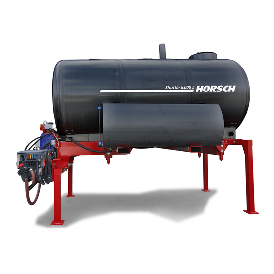
Attachment Overview Shuttle 8,000 L liquid fertiliser/crop protection agent 1 Spraying mixture container 2 Filling dome 3 Illuviation valve 4 Hollow profiles for forklift transport 5 Filling port 6 Delivery pump 7 Fresh water pump 8 Fresh water tank (Tank 1) 9 Access steps 10 Transport and safety container for personal protective outfit / crop protection agent... -
Page 24: Hydraulics
Hydraulics Hochdruckreiniger Frischwasserpumpe Förderpumpe 25 l/min 14 l/min 00111116 00111123 80 l/min 200bar 5bar 1 Hydraulic supply vehicle side 2 Flow restrictor 3 High pressure cleaner 4 Fresh water pump 5 Delivery pump 6 Flow control valve 7 Fresh water pump / high pressure cleaner operation 8 Delivery pump operation... -
Page 25: Lighting
Lighting The Shuttle is equipped with lighting. Connection to the carrier vehicle is made with 15- pin plug-and-socket connectors 24 V ISO 12098. Plugs and cable assignment Contact Function Conductor Cable colour cross-section Direction indicator left 1.5 mm yellow Direction indicator right 1.5 mm green Rear fog light... -
Page 26: Spraying Mixture Container
Spraying mixture Filling dome container DANGER WARNING Danger of injury by poisonous vapours! Do ¾ not climb into the spraying mixture container! Danger of poisoning - Do not climb into the spraying mixture container! The spraying mixture container is designed to hold water, spraying agents and fertilisers. -
Page 27: Access Steps
Access steps WARNING DANGER Danger of traffic accidents. Always fold up the access ladder to the trans- ¾ Serious accidents by falling down! port position before transport travel. No passengers are allowed to ride on the ¾ machine! WARNING When climbing up, always maintain contact ¾... -
Page 28: Hand Washing Tank
Transport and safety The tank lids with ventilation for the fresh water tanks are located at the top. container WARNING There is a transport and safety container on the left side of the machine. It is used to store Danger of poisoning by contaminated water personal protective outfit and accessories. -
Page 29: Operation
On the vehicle side it must be ensured with a fixed half of the screw coupling DN 20 (Art. No. WARNING 00110840) or DN 25 (Art. No. 00110904) that the carrier vehicle is compatible with the HORSCH Dropping or lowering machine parts can cause Shuttle. severe crushing injuries etc.! Instruct persons to leave the danger zone. -
Page 30: Electric System
Hydraulic system limits The system voltage of the carrier vehicle is 24 V, the electronic level indicator TankControl Volume flow rate (l/min) max. 80 ± 10 requires an input voltage of 12 V. The supply Hydraulic pressure (bar) max. 210 voltage of TankControl is also taken from the 15-pin connector and lowered with the help of To prevent exceeding the maximum volume flow... -
Page 31: Hitching/Unhitching
Hitching/Unhitching Release the bolt on the supports, remove the ¾ supports, plug them into parking position and secure with bolts. (dismantle the parking sup- ports as an option). DANGER Serious accidents from dropping loads! No persons may be present under suspended loads. - Page 32 Secure the attachment at all points with bolts. ¾ Attachment bolt retainer - at the front in direction of travel Remove the rear parking supports (optional) Lift the attachment onto the truck. ¾ Guide the spigots into the openings provided ¾...
-
Page 33: Unhitching
Connect the connections for the power supply Disconnect the connections for the power ¾ ¾ on the attachment. supply on the attachment. 15-pin plug for power supply 15-pin plug for power supply Remove the retainer of the mounting bolts ¾ and remove the bolts. - Page 34 Mounting the front parking supports (optional) Mounting the rear parking supports (optional) Lower the attachment to the ground. ¾...
-
Page 35: Working With The Machine
Working with the machine Preparing the spraying mixture WARNING DANGER Risk of health damage through contact with crop protection agents. Danger caused by accidental contact with Crop protection agents are harmful to health. crop protection agents and/or spraying Wear personal protective outfit during all ¾... -
Page 36: General Procedure
General procedure Do not leave the prepared spraying mixture, ¾ unused crop protection agent, uncleaned crop protection agent canisters and the uncleaned 1. Determine the required water and preparation machine unattended to avoid dangers to other application quantity as per instructions for use persons. -
Page 37: Calculating Filling / Refill Quantities
Calculating filling / refill Question 1: quantities How many l or kg preparation must be metered for one container filling? Example 1: Filling quantities Calculation formula and answer to The following is known: question 1: Rated tank volume 1000 l Residual quantity in tank 0 l Water refill quantity [l] x concentration [%] Required water 400 l/ha... -
Page 38: Filling With Water
Filling with water When filling the spraying mixture container ¾ pay attention to sealed surfaces, so that no wash runs into the sewer system. NOTE No foam must escape from the spraying mix- ¾ ture container during filling. When filling, pay attention to the permissible ¾... -
Page 39: External Control Terminal
WARNING Danger to health through contact with spray- ing mixture if the filling opening of the spraying mixture container is not closed correctly. Before each transport travel, check whether ¾ the filling opening of the spraying mixture container is closed properly. Pump and operating elements Immediately replace a damaged or worn lid ¾... -
Page 40: Filling Port
Filling port Filling via filling port The filling hose and the front connection on the CAUTION spraying mixture container are equipped with couplings that can only be connected or discon- Damage caused by overfilling the closed spray- nected when both valves are closed. The lock is ing mixture container. -
Page 41: Filling Via Filling Dome
Fresh water tank filling (Tank 1) 7. Move lever 7 to the centre position to turn off the pump again. The fresh water tank (Tank 1) is located at the 8. Close the closure of the filling hose. left in the direction of travel and has a capacity 9. -
Page 42: Fresh Water Tank Filling (Tank 2)
Illuviation valve Fresh water tank filling (Tank 2) The fresh water tank (Tank 2) is located at the WARNING right in the direction of travel and has a capacity of 800 litres. Danger to the environment and health from crop protection agent. - Page 43 Washing gun The illuviation valve can be cleaned after filling with the washing gun. Apart from this, deposited residues can be flushed out of the canisters. 7 Connection external filling devices 8 Washing gun 9 Activate/deactivate the canister flushing 10 Activate/deactivate the washing gun Washing gun 11 Activate/deactivate shock nozzle ¾...
-
Page 44: Flushing In Preparations
Flushing in preparations Illuviation valve DANGER Wear appropriate protective outfit for the illuvi- ation of the preparations. Observe the regulations and notes of the crop Fitting protection manufacturer! A Main filling valve Crop protection agent and carbonyl diamide are B Fitting valve poured into the illuviation valve, dissolved and C Lever for speed control of the delivery pump drawn in. - Page 45 11. Close the switch-over ball valve of the Open valve 4. illuviation valve again. Turn the lever 6 up to fresh water pump. Water 12. Move lever 7 to the centre position to turn is suctioned from the fresh water tank. off the pump again.
-
Page 46: Canister Cleaning
Canister cleaning NOTE Canister cleaning with fresh water Water or chemical emerges from the canister flushing nozzle, when the pressure plate is NOTE pressed down. Cleaning the canisters with fresh water reduces the spraying mixture concentration. Empty preparation containers 1. Open the lid of the illuviation valve. Thoroughly wash out empty preparation con- ¾... -
Page 47: Mixing Solution
Mixing solution Filling the crop protection sprayer WARNING CAUTION Danger to the environment and health from crop protection agent. Danger of machine damage. Mixing the solution is only allowed at the edge ¾ of the field, for example, while waiting for the Make sure when filling and emptying the crop crop protection sprayer. -
Page 48: Cleaning
Cleaning Internal cleaning of spraying mixture container CAUTION 1. Close valve A. 2. Open valve B. Contamination with crop protection agents. Wear the personal protective outfit when clea- 3. Close valve 3. ning the crop protection sprayer! 4. Depending on the filling level, open valve 2 or 4. - Page 49 High pressure cleaner The Shuttle is equipped with a high pressure cleaner (optional) that can be used to clean the machine. NOTE The high pressure cleaner is powered hydrauli- Do not clean new machines with a steam jet cally and supplied from the fresh water tank or high pressure cleaner.
-
Page 50: Filter
Working lights Filter An LED spotlight is attached to the spraying mix- CAUTION ture container to light the external control unit. Spraying mixture running out! Wear personal protective outfit! NOTE Clean the filter after suctioning contaminated ¾ water. The filter should be cleaned daily to prevent ¾... -
Page 51: Care And Maintenance
Reattach all protective features that were Use only spare parts approved by HORSCH. ¾ ¾ removed for the purpose of care, service and Use only spare hoses approved by HORSCH ¾... - Page 52 Carry out repairs only on machines shut down Maintenance intervals ¾ and secured against restarting. The maintenance intervals are determined by Disconnect both the machine cable and the ¾ many different factors. current supply from the on-board computer For example, the different operating conditions, before starting care and maintenance work.
- Page 53 Lubricating the machine The machine should be lubricated at regular intervals and after each cleaning action. This ensures operability and reduces repair costs and downtimes. CAUTION Hygiene Lubricants and mineral oil products are not harmful to health as long as they are used as instructed.
-
Page 54: Maintenance Overview
Maintenance overview Maintenance location Work instructions Interval After 10 operating hours Retighten all screw and plug-in Even firmly tightened screw connections can come loose Once connections as well as the hydraulic (e.g. because of material settlement or paint residues connections. between the screw elements). - Page 55 Maintenance location Work instructions Interval Water system Pump Cleaning, flushing daily Spraying mixture container Filter Dome screen Pump check for leaks daily Hose assembly check for leaks 50 h Pump Check pressure and oil level 50 h Safety installations Lighting and warning boards Check condition and function daily Warning and safety stickers...
-
Page 56: Maintenance Of The Hydraulic System
Additional specifications of the hydraulic system once every year! (circuit diagrams, etc.) can be obtained from the Replace hydraulic hoses if damaged or exces- ¾ HORSCH service department. sively aged! Use only original hydraulic hoses from HORSCH! NOTE Make sure the hydraulics is depressurised when... -
Page 57: Inspection Criteria For Hydraulic Hoses
NOTE NOTE The following inspection criteria must be ob- Use only original spare hoses from HORSCH. served in the interest of your own safety and to These spare hoses withstand the chemical, reduce environmental damages! mechanical and thermal loads. -
Page 58: Storage
HORSCH sales partner in due time. Your HORSCH sales partner will be in a much better position to execute the maintenance service and possibly necessary repairs outside the season. -
Page 59: Waste Disposal
Attention must be paid to all valid regulations. Decommissioning and waste disposal must only be carried out by operators who have been trained by HORSCH. Contact a waste disposal company, if this should be necessary. -
Page 60: Appendix
Appendix Tightening torques NOTE The tightening torques only serve as guidelines and are generally valid. Actual data given at the • corresponding points in the operating instructions have priority. Screws and nuts must thereby not be treated with lubricant, since this would change the friction value. •... - Page 61 Inch screws Tightening torques - inch screws in Nm Screw Strength 2 Strength 5 Strength 8 diameter No marks on head 3 marks on head 6 marks on head Inch Coarse Fine thread Coarse Fine thread Coarse Fine thread thread thread thread 12.2...
-
Page 62: Index
Index Hand washing tank 17,24 Accessories 6 Height 17 Access steps 19,23 High pressure cleaner 44,45 Acknowledgement of receipt 4 Hitching 27 Attachment 19 Hose clamps 47 Axle load 17 Hydraulic hoses 53 Hydraulics 10,17,20,50 Cable assignment 21 Hydraulic system 25,52 Canister 42 Hydraulic system limits 26 Canister flushing 38... - Page 63 Safety 6 Safety and protective features 47 Safety container 24 Safety stickers 14 Screw connections 13,48 Serial number 17 Service 5 Shock nozzle 38 Spare parts 6,47 Spraying mixture 31,47 Spraying mixture container 17,19,22,36 Stickers 14 Storage 54 Switch-over ball valve 40 Technical data 17 Technical limiting values 10 Traffic 8...
- Page 65 All details on technical specifications and pictograms are approximate and for information only. Subject to technical product revisions. HORSCH Maschinen GmbH Tel.: +49 94 31 7143-0 Sitzenhof 1 Fax: +49 94 31 7143-9200 92421 Schwandorf E-Mail: info@horsch.com www.horsch.com...
Need help?
Do you have a question about the Shuttle 8.000 L and is the answer not in the manual?
Questions and answers