
Related Manuals for horsch Tiger MT Series


Summary of Contents for horsch Tiger MT Series
- Page 1 OPERATING INSTRUCTIONS Tiger MT TRANSLATION OF THE ORIGINAL OPERATING INSTRUCTIONS READ CAREFULLY PRIOR TO STARTING UP! KEEP OPERATING INSTRUCTIONS IN A SAFE PLACE! ART.: 8058 0207 ISSUE: 01/2017...
- Page 3 HORSCH: ..............Confirmation of receipt of machinery Warranty claims become only effective when the first use of the machine is reported to HORSCH Maschinen GmbH within a week. www.horsch.com under SERVICE PARTNERBEREICH an interactive PDF form is available for down- load for this purpose (not available in all languages).
- Page 4 EC Declaration of Conformity Exchangeable equipment (Directive 2006/42/EC) The manufacturer HORSCH Maschinen GmbH Sitzenhof 1 D- 92421 Schwandorf hereby declares, that the product, Designation of machine: Cultivation tool Machine type: Tiger 3 MT from serial number: 34631616 Tiger 4 MT / 4 MT rigid...
-
Page 6: Table Of Contents
Table of contents Introduction ...........4 Assembly groups ........44 Foreword ............4 Tines .............44 Notes on representation .........4 MulchMix coulter...........44 Service............5 Levelling discs ...........45 Warranty claim processing ......5 Border discs..........47 Consequential damage........5 DiscSystem ...........49 Double-RollPack Packer.......49 Safety and responsibility ......6 Intended use ...........6 Operation .............50 Qualification of personnel .......7 Commissioning / Tractor change ....50... - Page 7 Depth setting ..........63 Basic setting ..........63 Tine field depth setting .......63 DiscSystem depth setting ......63 Use in the field ..........64 Checks............65 Optional equipment ........66 Brake system ..........66 Pneumatic brake ........66 Hydraulic brake ..........67 Parking brake ..........68 Optional equipment ........69 TopRing Packer ..........69 SteelDisc Packer ..........70 Rear drawing hook ........70 Fertiliser distribution ........71...
-
Page 8: Introduction
DANGER to the safety notes! Highlights a danger that will lead to death or HORSCH will not assume liability for any dam- severe injury if it is not avoided. age or malfunctions resulting from failure to comply with the operating instructions. -
Page 9: Service
Service Consequential damage HORSCH Company would like you to be completely The machine has been manufactured by satisfied with your machine and our services. HORSCH with greatest care. However, despite the intended use deviations in placing quantity If you encounter any problems, please feel free up to total failure may be caused by e.g.:... -
Page 10: Safety And Responsibility
Safety and Spare parts Genuine spare parts and accessories from responsibility HORSCH have been specially designed for this machine. Spare parts and accessories which are not deliv- The following warnings and safety notes apply ered by us, have not been tested or approved by us. -
Page 11: Qualification Of Personnel
The person has understood the operating ¾ service personnel from HORSCH. This refers to instructions and is able to implement the in- the following activities: formation given in the operating instructions Loading and transport accordingly. -
Page 12: Personal Protective Equipment
Personal protective Clean soil from the folding areas before fold- ¾ ing up. Otherwise there could be damage to equipment the mechanics. If present: Secure the hydraulic cylinders on ¾ Missing or incomplete protective equipment undercarriage and drawbar in transport posi- increases the risk of health damage. -
Page 13: Safety In Operation
Have damage, that could affect safety and ¾ authorized dealer or a HORSCH employee. that cannot be rectified by yourself, rectified The machine registration form must be com- by a qualified expert workshop. - Page 14 Use only appropriate means when searching ¾ specially trained by HORSCH. for leaks. Repair any damage immediately! Oil sprays can cause injuries and fire! Overhead lines Power sockets and connectors on the hydrau- ¾...
- Page 15 Use in the field What to do in case of voltage flashover Voltage flashover generates high electric volt- ages on the outside of the machine. This results DANGER in extreme voltage differences at the ground No passengers are allowed to ride on the around the machine.
-
Page 16: Fertiliser And Dressed Seed
Structural changes and extensions must only ¾ Environmental protection be made in an authorized workshop or by an operator who has been trained by HORSCH. Operating materials such as hydraulic oil, lubri- Comply with country specific instructions for ¾ cants, etc. can damage the environment and the weights, weight distribution and dimensions. -
Page 17: Care And Maintenance
HORSCH for this purpose. Do not clean new machines with a steam jet of a high pressure cleaner. The paint takes approx. -
Page 18: Danger Zone
Danger zone Failing to pay attention to the danger zone can The area marked red indicates the danger zone result in severe or even fatal physical injuries. of the machine: Do not stand under lifted loads. Lower such ¾ loads to the ground first. Instruct persons to leave the danger zone ¾... -
Page 19: Safety Stickers
Safety stickers Safety stickers on the machine warn of hazards Clean soiled safety stickers. ¾ at dangerous points and are an important part Damaged or illegible safety stickers must be ¾ of the safety equipment of the machine. Miss- replaced immediately. ing safety stickers increase the risk of severe or Affix the specified safety stickers on spare parts. - Page 20 In order to prevent eye injuries, do not look directly at the beam area when the radar sensor is switched on! 00380894 Remaining in the danger zone is only permitted when the lifting cylinder pin is inserted. 00380896 Remaining in the danger zone is only permitted if the safety support is in place.
- Page 21 Position of safety stickers (depending on equipment) Tiger 8 MT...
-
Page 22: Commissioning
If the machine is hitched up in two-point mode, ¾ These work activities may be carried out only by the tractor link arms must be blocked against persons trained by HORSCH for this purpose. swinging sideways. On a trailer or low loader the machine must ¾... -
Page 23: Technical Data
Technical data Tiger 3 MT 4 MT rigid Working width (m) 3.00 4.00 Transport width (m) 3.00 4.05 Transport height (m) 2.40 2.40 Length with tyre packer 7.50-16 (m) 8.30 8.60 Length with tyre packer 210/95-24 (m) 8.65 Weight (kg) 4,215 5,525 Number of discs in DiscSystem... - Page 24 Tiger 4 MT 5 MT Working width (m) 4.00 4.80 Transport width (m) 3.00 3.00 Transport height (m) 2.90 3.20 Length with tyre packer 7.50-16 (m) 8.55 8.55 Length with tyre packer 210/95-24 (m) 8.90 8.90 Weight (kg) 6,575 7,425 Number of discs in DiscSystem Space between discs (cm) Number of tines...
- Page 25 Tiger 6 MT 8 MT Working width (m) 6.00 7.50 Transport width (m) 3.00 3.00 Transport height (m) 3.60 4.00 / 4.15 (with levelling discs, 2-row, Ø 46 cm) Length with tyre packer 7.50-16 (m) 8.55 8.55 Length with tyre packer 210/95-24 (m) 8.90 8.90 Weight (kg)
-
Page 26: Type Plate
8300 3000 Tiger 3 MT 8550 3000 Tiger 8 MT Type plate The type plate with the CE-mark is located on the frame of the machine. Data on the type plate: Serial number Permissible total weight Drawbar load (= DL) Axle load Machine type Year of construction... -
Page 27: Requirements For The Tractor
Requirements for the tractor WARNING Danger of accident! Observe the permissible values of the tractor ¾ for axle loads, total weight, tyre load bearing capacity and air pressure. Verify the suitability of the tractor before com- ¾ missioning. The tractor must meet the following require- ments to be able to use the machine as intended: Engine power Tiger 3 MT... - Page 28 Hydraulics Maximum system pressure 210 bar Oil grade Mineral hydraulic oil Number of dual-acting control units Tiger 3 MT 2 (+1 bout marker) Tiger 4 MT rigid 3 (+1 bout marker) Tiger 4 MT (tractor link arm hitching) 3 (+1 bout marker) Tiger 4 MT (swinging drawbar hitching) 4 (+1 bout marker) Tiger 5 MT (tractor link arm hitching)
-
Page 29: Calculating The Ballasting
Calculating the ballasting Required data: The permissible total weight, the permissible axle loads and the load bearing capacity of the tyres must not be exceeded when mounting or hitching up implements. The front axle of the tractor must always be loaded with at least 20 % of the curb weight of the tractor. - Page 30 1. Calculation of minimum front ballasting 4. Calculation of the actual total weight with rear implement: • (c + d) - T • b + 0.2 • T • b Enter the result of the calculated total weight and a + b V min the permissible total weight from the operating instructions of the tractor into the table.
-
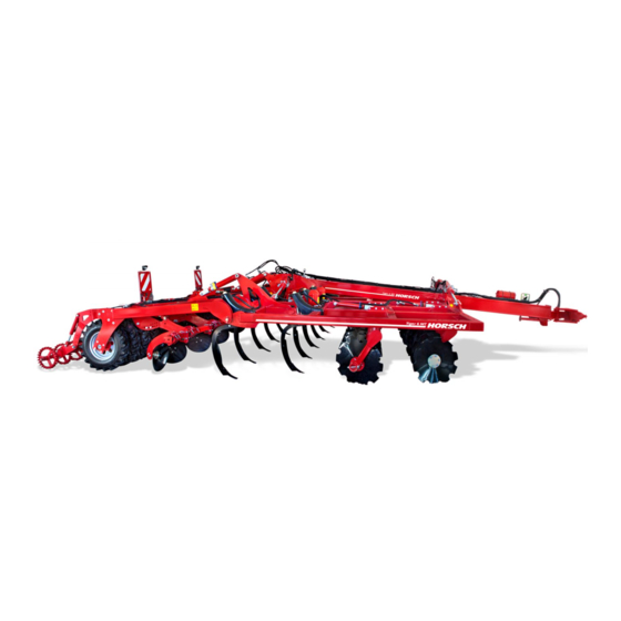
Page 31: Design
Design Overview Tiger 6 MT 1 Drawbar (tractor link arm hitching) 2 DiscSystem, 2-row 3 Tine field, 2-row 4 Levelling discs, 1-row 5 Tyre packer, here: 7.50-16 AS Ø 78 cm 6 TopRing packer (option) 7 Lighting... -
Page 32: Hydraulics
Hydraulics Tiger 3 MT Lifting/lowering Tiger 3 MT DiscSystem Hydraulic connection lifting/lowering Connection lift TopRing Packer (option) Lock valve, double 90° Connection lower TopRing Packer (option) Hydraulic cylinder lift/lower Hydraulic cylinder levelling discs Lock valve levelling discs Hydraulic connection DiscSystem Lock valve, double 90°... - Page 33 Tiger 4 MT swinging drawbar hitching lifting/lowering C1 V1 C1 V1 Hydraulic connection wings 10 Connection unfold drawbar (option) Hydraulic connection lifting/lowering 11 Lock valve, double 90° Hydraulic connection drawbar cylinder 12 Lock valve single 90° Lowering brake valve 13 Lock valve lighting Connection lift TopRing Packer 14 Connection lower TopRing Packer Hydraulic cylinder drawbar...
- Page 34 Tiger 4 MT tractor link arm hitching lifting/lowering C1 V1 C1 V1 Hydraulic connection wings Lock valve, double 90° Hydraulic connection lifting/lowering 10 Lock valve single 90° Lowering brake valve 11 Lock valve lighting Connection lift TopRing Packer 12 Connection lower TopRing Packer Three-way rotary spool valve 13 Hydraulic cylinder lift/lower outside Hydraulic cylinder wings...
- Page 35 Tiger 4 MT swinging drawbar hitching large tyre packer lifting/lowering C1 V1 C1 V1 Hydraulic connection wings 10 Connection unfold drawbar (option) Hydraulic connection lifting/lowering 11 Lock valve, double 90° Hydraulic connection drawbar cylinder 12 Lock valve single 90° Lowering brake valve 13 Connection lower TopRing Packer Connection lift TopRing Packer 14 Hydraulic cylinder lift/lower outside...
- Page 36 Tiger 4 MT tractor link arm hitching large tyre packer lifting/lowering C1 V1 C1 V1 Hydraulic connection wings Lock valve, double 90° Hydraulic connection lifting/lowering 10 Lock valve single 90° Lowering brake valve 11 Connection lower TopRing Packer Connection lift TopRing Packer 12 Hydraulic cylinder lift/lower outside Three-way rotary spool valve 13 Hydraulic cylinder lift/lower inside...
- Page 37 Tiger 4 MT rigid lifting/lowering Hydraulic connection lifting/lowering Connection lift TopRing Packer Lock valve, double 90° Connection lower TopRing Packer Hydraulic cylinder Lift/Lower Hydraulic cylinder levelling discs Lock valve levelling discs Tiger 4 MT rigid DiscSystem Hydraulic connection DiscSystem Lock valve single 180° Pressure gauge DiscSystem Pressure accumulator Hydraulic cylinder DiscSystem...
- Page 38 Tiger 5/6 MT tractor link arm hitching C1 V1 C1 V1 Hydraulic connection wings Lock valve, double 90° Hydraulic connection lifting/lowering 10 Lock valve single 90° Lowering brake valve 11 Connection lower TopRing Packer Connection lift TopRing Packer 12 Hydraulic cylinder lift/lower outside Three-way rotary spool valve 13 Hydraulic cylinder lift/lower inside Hydraulic cylinderwings...
- Page 39 Tiger 5/6/8 MT swinging drawbar hitching C1 V1 C1 V1 Hydraulic connection wings 10 Connection unfold drawbar (option) Hydraulic connection lifting/lowering 11 Lock valve, double 90° Hydraulic connectiondrawbar cylinder 12 Lock valve single 90° Lowering brake valve 13 Connection lower TopRing Packer Connection lift TopRing Packer 14 Hydraulic cylinder lift/lower outside Hydraulic cylinder drawbar...
- Page 40 Tiger 5/6/8 MT DiscSystem Hydraulic connection DiscSystem Lock valve single 180° Pressure gauge DiscSystem Pressure accumulator Hydraulic cylinder DiscSystem...
-
Page 41: Identification Of Hydraulic Hoses
Identification of hydraulic hoses The symbol is always located above the hose that requires pressure to bring the machine in transport position (lift out, folding, etc.). Lift / lower Folding Bout marker Tools... -
Page 42: Aluminium Clips
Aluminium clips NOTE The aluminium clips are placed on hydraulic Pay attention to the ratio on the machine, see ¾ cylinders depending on the operating states, Depth setting. see chapter Operation. Different aluminium clips The thickness of the clips differs according to colour: Colour blue... -
Page 43: Lighting
Lighting WARNING Traffic accidents caused by defective lighting. Check the lighting before setting off. ¾ Check warning notices and lamps for cleanliness. ¾ LED: NOTE Check the plug-and-socket connection on all ¾ lighting units (right, left, front, rear) for firm seating: 7-pin plug Rear light, right... -
Page 44: Instruction Stickers
Hook the sling gear (chains, ropes etc.) into this loading hook during loading. Loading work only by operators trained by HORSCH! With DuoDrill equipment; insert the alumin- ium clips on the piston rods before folding. Tighten with the appropriate torque... - Page 45 Trägerfolie: Signalweiß RAL 9003 Darstellung: Signalschwarz RAL 9004 Aufkleber nach HO-Norm 1007 Lfd. Nr. Stück Benennung Rohmaß Werkstoff 2 : 1 HORSCH Maschinen GmbH Maßstab: Allgemein- Werkstück- Sitzenhof 1 toleranz kanten Urheberschutz: Für diese technische Unterlage 92421 Schwandorf DIN 6784...
- Page 46 Coulter system - locking Block TopRing packer 00380580 Hitching / uncoupling Tightening torque disc bearings (only for France) „ Atteler à un tracteur dont le relevage est équipé de dispositifs de blocage latéraux et verticaux“. „Pour circuler sur la route, respecter la hauteur d’attelage spécifiée dans la notice d’utilisation et bloquer le relevage“.
- Page 47 Swinging drawbar hitching cat. 5 Tightening torque packer connection KAT 5 ! 00380579 00380547 Risk of collision Tiger 4 - 8 with Pronto TD Risk of collision for machines with DuoDrill Risk of collision Tiger 4 - 6 with SteelDisc Packer 00385483...
-
Page 48: Assembly Groups
Assembly groups NOTE The stone release protection serves as protec- Tines tion system against obstacles in the field. Reduce the working depth if the stone re- ¾ The tines are robust, of simple design and suit- lease protection is often triggered under hard able for all types of soil. -
Page 49: Levelling Discs
MulchMix, LD and ULD The discs distribute the thrown up soil and level coulter (coulter tips, guide plates, wings): the ground in front of the packer. Use only original HORSCH wear items. ¾ Use new screws and nuts with each replace- ¾... - Page 50 2. Lower the machine with pressure until the Conversion from transport to working levelling discs rest against the bolts for the position depth adjustment. NOTE Depending on the working width a certain ¾ amount of conversion work is required to change from transport to working position Levelling discs Hole pattern for depth adjustment with bolt...
-
Page 51: Border Discs
Border discs NOTE The border discs prevent the formation of dams Move the levelling discs again to working ¾ at both sides of the machine. position before use in the field. Maintenance Bearings are oil-filled and therefore maintenance free. Tiger MT border disc Setting Adjust the border discs to the conditions of use in the field. - Page 52 Angle of attack adjustment of the discs WARNING The angle of attack of the discs must be adjusted Risk of injury from the border disc falling down. to the working speed and the amount of earth and harvest residues thrown up. Fold down the border disc carefully and do not ¾...
-
Page 53: Discsystem
DiscSystem Double-RollPack Packer The 2-row DiscSystem of the Tiger MT is located Tiger 4 MT rigid is available with a dual RollPack in front of the tine field. packer. The large serrated discs cut large quantities of The machine runs on the transport undercar- harvest residues and are also suitable for use riage during road travel. -
Page 54: Operation
Operation Connecting/Parking Whenever working on the machine pay attention to the associated safety DANGER notes in the chapter "Safety and There is a risk that persons may become prevention of accidents" as well as crushed and severely injured between machine the accident prevention instructions! and tractor! Instruct persons to leave the area between... -
Page 55: Connecting
Connecting Tiger 4 MT swinging drawbar hitching 1. Clean the towing facilities of machine and DANGER tractor and check for wear. Serious accidents caused by the machine roll- 2. Move the tractor to the machine and set the ing away! brake. -
Page 56: Tiger 5 - 8 Mt - Swinging Drawbar Hitching
Transport position Tiger 5 - 8 MT - swinging drawbar hitching WARNING NOTE Danger of road accidents caused by losing the The Tiger 8 MT with swinging drawbar hitching machine or machine parts. must only be operated with drawbar eye and Check all interlocks before starting to drive. -
Page 57: Tiger 4 Mt Tractor Link Arm Hitching
Tiger 4 MT tractor link arm Tiger 4 MT swinging drawbar hitching hitching 1. Fully raise the machine via packer and trac- 1. Releasing the parking brake (option). tor link arm. 2. Fully raise the machine via packer and 2. Lift the DiscSystem separately via the tractor drawbar. -
Page 58: Tiger 5 - 6 Mt - Tractor Link Arm Hitching
Tiger 5 - 6 MT - tractor link arm Tiger 5 - 8 MT - swinging drawbar hitching hitching 1. Fully raise the machine via packer and trac- 1. Fully raise the machine via packer and tor link arm. drawbar. 2. - Page 59 Position of control units during transport travel Floating position Locked position Supply Position Control unit Folding Lift/lower (undercarriage) Tools Drawbar lifting/lowering (only with swinging drawbar hitching)
-
Page 60: Parking
Parking Tiger 4 MT tractor link arm hitching 1. Fully lift out the machine via packer and trac- DANGER tor link arm. Serious accidents caused by the machine roll- 2. Fold and secure the support. ing away! Before unhitching secure the machine with the 3. -
Page 61: Tiger 4 Mt Swinging Drawbar Hitching
Tiger 4 MT swinging drawbar Tiger 5 - 6 MT - tractor link arm hitching hitching 1. Fully lift out the machine via packer and 1. Fully lift out the machine via packer and trac- drawbar. tor link arm. 2. Fold and secure the support. 2. -
Page 62: Tiger 5 - 8 Mt - Swinging Drawbar Hitching
Folding Tiger 5 - 8 MT - swinging drawbar hitching WARNING 1. Fully lift out the machine via packer and drawbar. Dropping or lowering machine parts can cause severe crushing injuries etc.! 2. Fold and secure the support. Instruct persons to leave the danger zone. 3. -
Page 63: Tiger 4 Mt Swinging Drawbar Hitching
Tiger 4 MT swinging drawbar Tiger 5 - 8 MT - swinging drawbar hitching hitching 1. Open the lock valve on the cylinder of the 1. Open the lock valve on the cylinder of the drawbar. drawbar. 2. Switch the drawbar lifting/lowering control unit to 2. -
Page 64: Folding
Folding Tiger 4 MT swinging drawbar hitching Tiger 4 MT tractor link arm 1. Fully raise the machine via packer and hitching drawbar. 1. Fully raise the machine via packer and trac- 2. Lift the DiscSystem separately via the tractor tor link arm. -
Page 65: Tiger 5 - 6 Mt - Tractor Link Arm Hitching
Tiger 5 - 6 MT - tractor link arm Tiger 5 - 8 MT - swinging drawbar hitching hitching 1. Fully raise the machine via packer and 1. Fully raise the machine via packer and trac- drawbar. tor link arm. 2. -
Page 66: Folding Tiger 5 - 8 Mt With Duodrill
Folding Tiger 5 - 8 MT with DuoDrill With the cultivator is equipped with a DuoDrill drill unit, an aluminium clip with a thickness of 50-mm must be added to the hydraulic cylinders of the side packers before folding. Sticker "Attention: Insert clip before folding" The aluminium clip prevents collision between packer and DuoDrill facility. -
Page 67: Depth Setting
Depth setting DiscSystem depth setting Perform setting of the DiscSystems in the The working depth is determined by inserting ¾ field. aluminium clips on the hydraulic cylinders of the packer. Starting from the basic setting, remove alu- ¾ The machine is levelled via the tractor link arm minium clips from the cylinders of the Disc- or drawbar. -
Page 68: Use In The Field
Use in the field Position of control units during use in the field Floating position Locked position Supply Position Control unit Folding Lift/lower (undercarriage) Tools Tractor link arm Drawbar lifting/lowering (only with swinging drawbar hitching) -
Page 69: Checks
Checks The working quality essentially depends on the adjustments and checks made prior to and dur- ing use, as well as on regular care and mainte- nance of the machine. Carry out all maintenance tasks and adjust- ¾ ments before starting to work. Checks before and during use on the field Machine... -
Page 70: Optional Equipment
Optional equipment Connection Connect the Coupling head "Brake" (yel- low) first. Brake system Then connect the Coupling head "Provi- sion" (red). The machine can be equipped with a pneumatic or a hydraulic brake system. The machine is Release the parking brake. equipped with a parking brake for safe parking Unhitching DANGER... -
Page 71: Hydraulic Brake
Hydraulic brake WARNING The hydraulic line controls the brake power to Danger of traffic accidents caused by brake the brake cylinders. failure! During commissioning or after long periods of rest: The brake inlet pressure should not exceed Fill the pressure accumulator for emergency ¾... -
Page 72: Parking Brake
Maintenance Check brake lines and hoses for signs of ¾ damage. Check the brake pads for wear. ¾ Parking brake DANGER Uncontrolled rolling of the machine can cause severe injuries by crushing or rolling over. Park the machine only on level ground with ¾... -
Page 73: Optional Equipment
Optional equipment Setting Adjust the TopRing packer when all other set- tings have been made on the machine. Follow The Tiger can also be operated without these theDepth setting section in this regard. accessories. The description of the accessories also contains 1. -
Page 74: Steeldisc Packer
HORSCH Optipack. With its excellent cutting effect and its high The hook is designed for HORSCH implements. weight, the packer crushes and compresses Other machines with a trailer nose weight of up down to deeper layers. -
Page 75: Fertiliser Distribution
Fertiliser distribution DANGER Soil cultivation and fertilising can be combined Danger of serious traffic accidents. by using the fertiliser distributor. It mainly con- Never connect machines to the Tiger in public ¾ sists of the distributor tower, the hose system road traffic. -
Page 76: Bout Marker
Bout marker Adjusting the fertiliser placement The fertiliser placement optionally takes place The Tigers 4 - 6 MT can be equipped with a by the coulter into the ground, bout marker. • behind the coulter on the surface of the field, •... -
Page 77: Rear Two-Point Hitching
Rear two-point hitching Aggressiveness of bout markers Two-point hitching (Cat. III) can be mounted to the Tiger MT. Hitching is designed for HORSCH drills. Bout marker disc setting Adjust the aggressiveness of the bout markers ¾ according to the soil conditions. -
Page 78: Maintenance And Servicing
Maintenance and Maintenance Periods Servicing The maintenance intervals are determined by various different factors. Various operating, weather and soil conditions as well as working speeds affect the mainte- CAUTION nance intervals, but also the quality of the lu- Observe the safety instructions for maintenance bricants and cleaning agents used determines and servicing. -
Page 79: Maintenance Overview
Maintenance overview Tiger MT Maintenance location Work instructions Interval After 10 operating hours Retighten all screw and plug-in Even firmly tightened screw connections can come loose Once connections as well as the hydraulic (e.g. because of material settlement or paint residues be- connections. - Page 80 Maintenance location Work instructions Interval Ball-and-socket coupling Before connecting: Clean ball and spherical cap. daily Replace the foam ring if damaged and/or heavily soiled. daily Place the foam ring. daily Check ball and spherical cap for wear. The wear limit 40 h has been reached when the gauge rests fully on the ball or enters the spherical cap.
- Page 81 Maintenance location Work instructions Interval Drawbar eye Fastening ¾ Check mounting screws for firm seat (560 Nm) 40 h Wear ¾ Replace the component concerned if one of the wear lim- 40 h its has been exceeded or fallen short of (workshop work): N o m i n a l d i m e n s i o n d i m e n s i o n...
- Page 82 Maintenance location Work instructions Interval Wheels / brakes Brake system Check condition and function daily Drain air reservoir daily Check brake lines and hoses for damages, crushing daily points and kinks Clean the pipe filter annually / as necessary Undercarriage / wheels Check for damage (cracks, etc.) daily Check fastening / retighten wheel nuts - see above...
- Page 83 Tiger MT lubrication points 4 rigid Interval Two-point drawbar - hinge bearing daily Two-point drawbar - pivot bearing daily Adjustable drawbar - bolt on main cylinder daily Packer arm bearing daily Safety pin bearing 40 h Disc axle 40 h Optional equipment Bout marker - hinge bearing 40 h...
-
Page 84: Appendix
Appendix Coulter arrangement The coulter spirals point in different directions to produce good mixing: Guide plate left Guide plateright NOTE Observe the correct direction of installation when replacing coulters! Tiger 3 MT Direction of travel... - Page 85 Tiger 4 MT rigid Direction of travel Tiger 4 MT Direction of travel...
- Page 86 Tiger 5 MT Direction of travel Tiger 6 MT Direction of travel...
- Page 87 Tiger 8 MT Direction of travel...
-
Page 88: Waste Disposal
Attention must be paid to all valid regulations. Decommissioning and waste disposal must only be carried out by operators who have been trained by HORSCH. Contact a waste disposal company, if this should be necessary. -
Page 89: Appendix
Appendix Tightening torques NOTE The tightening torques only serve as guidelines and are generally valid. Actual data given at the • corresponding points in the operating instructions have priority. Screws and nuts must thereby not be treated with lubricant, since this would change the friction value. •... - Page 90 Inch screws Tightening torques - inch screws in Nm Screw Strength 2 Strength 5 Strength 8 diameter No marks on head 3 marks on head 6 marks on head Inch Coarse Fine thread Coarse Fine thread Coarse Fine thread thread thread thread 12.2...
-
Page 91: Index
Index Height 19,20,21 Accessories 6 Accident prevention instructions 6 Hold-down 76 Hydraulic brake 67 Acknowledgement of receipt 4 Hydraulics 10,19,20,21,75 Aluminium clips 38 Installation 18 Ball 76 Ball-and-socket coupling 76 Brake 67 Levelling discs 45 Brake system 10,66,78 Liability 4 Break-away brake 67 Lighting 39 Lubrication points 79... - Page 92 Safety 6 Safety stickers 15 Screw connections 13 Service 5 Service brake system 10 Spare parts 6 speed 8 Spherical cap 76 Stickers 15,40 Technical data 19 Tines 44 Top speed 8,19,20,21 Tractor change 50 Traffic 8 Transport 8,18 Transport height 19,20,21 Transport position 52 Transport width 8,19,20,21 Type approval 8...
- Page 94 All details on technical specifications and pictograms are approximate and for information only. Subject to technical product revisions. HORSCH Maschinen GmbH Tel.: +49 94 31 7143-0 Sitzenhof 1 Fax: +49 94 31 7143-9200 92421 Schwandorf E-Mail: info@horsch.com www.horsch.com...
Need help?
Do you have a question about the Tiger MT Series and is the answer not in the manual?
Questions and answers