
Related Manuals for horsch Pronto 3 - 6 DC


Summary of Contents for horsch Pronto 3 - 6 DC
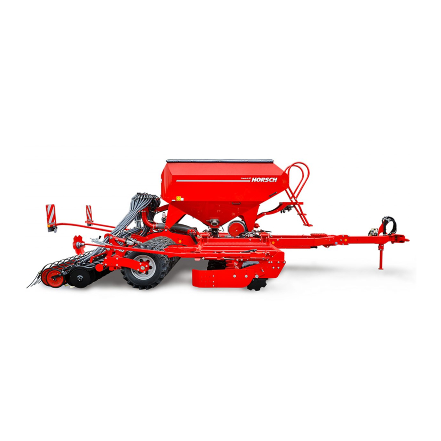
- Page 1 OPERATING INSTRUCTIONS Pronto 3 - 6 DC TRANSLATION OF THE ORIGINAL OPERATING INSTRUCTIONS READ CAREFULLY PRIOR TO STARTING UP! KEEP OPERATING INSTRUCTIONS IN A SAFE PLACE! ART.: 0208 8044 ISSUE: 05/2019...
- Page 3 HORSCH: ..............Confirmation of receipt of machinery Warranty claims become only effective when the first use of the machine is reported to HORSCH Maschinen GmbH within a week. www.horsch.com under SERVICE PARTNERBEREICH an interactive PDF form is available for down- load for this purpose (not available in all languages).
- Page 4 EG-Konformitätserklärung HORSCH Maschinen GmbH Sitzenhof 1, D-92421 Schwandorf erklärt hiermit in alleiniger Verantwortung als Hersteller, dass das nachfolgend genannte Produkt: Sägerät Typ: Pronto 3 DC Pronto 4 DC starr Pronto 4 DC Pronto 6 DC den einschlägigen grundlegenden Sicherheits- und Gesundheitsanforderungen der Richtlinie 2006/42/EG entspricht.
-
Page 6: Table Of Contents
Table of contents Introduction ...........4 Operation .............38 Foreword ............4 Commissioning / Tractor change ....38 Notes on representation .........4 Connecting/Parking ........38 Service............5 Connecting ...........39 Warranty claim processing ......5 Transport position .........40 Consequential damage........5 Parking ............42 Folding ............43 Safety and responsibility ......6 Unfolding ............43 Intended use ...........6 Folding ............43... - Page 7 Hydraulic coulter pressure adjustment ..88 Seed transport ..........63 Pre-emergence markers .......89 Single hopper ..........63 Micro-granulate facility........91 Twin hopper ..........63 Adjustment and operation ......91 Seed and fertiliser ........63 PPF System..........93 PPF system ..........64 Maize distributor ...........95 Using both hoppers for seed......64 Mounting the maize distributor ....95 G &...
-
Page 8: Introduction
DANGER to the safety notes! Highlights a danger that will lead to death or HORSCH will not assume liability for any dam- severe injury if it is not avoided. age or malfunctions resulting from failure of complying with the operating instructions. -
Page 9: Service
Service Consequential damage The machine has been manufactured by HORSCH Company would like you to be com- HORSCH with greatest care. However, despite pletely satisfied with your machine and our the intended use deviations in placing quantity services. up to total failure may be caused by e.g.:... -
Page 10: Safety And Responsibility
Safety and Spare parts Genuine spare parts and accessories from responsibility HORSCH have been specially designed for this machine. Spare parts and accessories which are not de- The following warnings and safety notes apply livered by us have not been tested or approved to all sections in these operating instructions. -
Page 11: Qualification Of Personnel
The person has understood the operating ¾ sponding personnel must have been trained by instructions and is able to implement the in- service personnel from HORSCH. This refers to formation given in the operating instructions the following activities: accordingly. Loading and transport •... -
Page 12: Personal Protective Outfit
Personal protective outfit For machines without brake select the weight ¾ of the tractor and the speed so that the ma- chine can be managed securely under all Missing or incomplete protective equipment conditions. Remember the extended breaking increases the risk of health damage. Personal distance. -
Page 13: Safety In Operation
Have damage that could affect safety and ¾ the authorized dealer or a HORSCH em- that cannot be rectified by you rectified by a ployee. qualified expert workshop. - Page 14 HORSCH for this purpose. In the case of injury, contact a doctor imme- ¾ diately!
- Page 15 What to do in case of voltage flashover Ensure sufficient overlapping of profile tube ¾ and PTO-shaft guard. Voltage flashover generates high electric volt- Allow PTO-shaft locks to click into place. ¾ ages on the outside of the machine. This results Secure the PTO-shaft guard with chains in extreme voltage differences at the ground ¾...
-
Page 16: Fertiliser And Dressed Seed
Do not use packer tyres or other rotating parts claim. to climb on the machine. These could rotate and you could be seriously injured by falling down. HORSCH is not liable for damages to life and limb as well as property damages resulting from unapproved retrofitting and conversions. -
Page 17: Care And Maintenance
Modifications and extensions approved by ¾ should stay clear of water, steam or cleaning HORSCH are only to be performed at an au- agents for reasons of safety or operation. Do thorized workshop or by an operator who has not aim the water jet directly at electrical or been trained by HORSCH for this purpose. -
Page 18: Danger Zone
Danger zone Failing to pay attention to the danger zone can The area marked red indicates the danger zone result in severe or even fatal physical injuries. of the machine: Do not stand under lifted loads. Lower such ¾ loads to the ground first. Instruct persons to leave the danger zone ¾... -
Page 19: Safety Stickers
Safety stickers Safety stickers on the machine warn of hazards Clean soiled safety stickers. ¾ at dangerous points and are an important part Damaged or illegible safety stickers must be ¾ of the safety equipment of the machine. Miss- replaced immediately. ing safety stickers increase the risk of severe or Affix the specified safety stickers on spare ¾... - Page 20 Keep sufficient safety distance to the slewing range of the machine. 00381117...
- Page 21 Position of safety stickers (depending on equipment) Safety stickers with the addition "2x" can be found on either side of the machine.
-
Page 22: Technical Data
Technical data Pronto 3 DC 4 DC Rigid version Length (m) 5.90 - 7.60 5.80 - 8.05 Working width (m) 3.00 4.00 Transport width (m) 3.00 4.00 Transport height (m) 2.95 2.95 Weight without / with PPF (kg) 3,300 - 5,000 4,800 - 7,300 Seed hopper capacity single hopper (l) 2,800... - Page 23 Pronto 4 DC 6 DC Length (m) 5.80 - 8.05 7.60 - 9.60 Working width (m) 4.00 6.00 Transport width (m) 3.00 3.00 Transport height (m) 2.95 3.60 Weight without / with PPF (kg) 4,800 - 7,300 6,500 - 10,000 Seed hopper capacity single hopper (l) 2,800 3,500...
-
Page 24: Type Plate
Model designation Serial number Type approval number Year of Sitzenhof 1 Made in Germany D-92421 Schwandorf construction Vehicle identification number Maschinen GmbH www.horsch.com (VIN) Technically permissible total weight A-0: A-1: Permissible drawbar load A-2: A-3: Technically permissible axle load (axles 1/2/3) - Page 25 Pronto 3 DC 6400 3000 Pronto 4 DC Rigid version 4000 6800 Pronto 4 DC 6900 3000 Pronto 6 DC 8200 3000...
-
Page 26: Requirements For The Tractor
Requirements for the tractor WARNING Risk of accident! Observe the permissible values of the tractor ¾ for axle loads, total weight, tyre load bearing capacity and air pressure. Verify the suitability of the tractor before com- ¾ missioning. The tractor must meet the following require- ments to be able to use the machine as intended: Implement attachment Pronto... - Page 27 Electrics / Control system Electric power supply 12 V Road lighting equipment: Socket, 7-pin, see chapter Lighting Control ISOBUS socket Hydraulics Maximum system pressure 210 bar Oil grade Mineral hydraulic oil Delivery rate (at fan speed 4500 rpm) Single hopper Twin hopper Pronto 3/4 DC rigid 50 l/min...
-
Page 28: Commissioning
These work activities may be carried out only by The permissible dimensions and weights for ¾ persons trained by HORSCH for this purpose. transport must be complied with. The tractor must be large enough so that ¾... -
Page 29: Calculating The Ballasting
Calculating the ballasting Required data: The permissible total weight, the permissible axle loads and the load bearing capacity of the tyres must not be exceeded when mounting or hitching up implements. The front axle of the tractor must always be loaded with at least 20 % of the curb weight of the tractor. - Page 30 1. Calculation of minimum front ballasting 4. Calculation of the actual total weight with rear implement: • (c + d) - T • b + 0.2 • T • b Enter the result of the calculated total weight and a + b V min the permissible total weight from the operating instructions of the tractor into the table.
-
Page 31: Construction
Construction Overview Pronto 6 DC Drawbar (tractor link arm hitching) Access steps Hopper (here: Twin hopper seed / fertiliser) Seed distributor tower Lighting Bout marker TurboDisc seed bar Tyre packers 10 DiscSystem, 2-row, Ø 46 cm 11 Front packer (option) -
Page 32: Hydraulics
Hydraulics WARNING Unintentional hydraulic movements may lead to severe accidents and injuries! Secure or lock the control units on the tractor. ¾ Instruct persons to leave the slewing range of ¾ foldable machine parts. Switch all control units to the locked position ¾... -
Page 33: Pronto 3 Dc
Pronto 3 DC... -
Page 34: Pronto 4 Dc Rigid Version
Pronto 4 DC Rigid version... -
Page 35: Pronto 4 Dc
Pronto 4 DC 00110352... -
Page 36: Pronto 6 Dc
Pronto 6 DC... -
Page 37: Marking Of Hydraulic Hoses
Marking of hydraulic hoses Auger Symbols on the handles of the hydraulic cou- plings indicate the function of the respective hoses: Pressureless return The return flow pressure of the leak oil line must not exceed 5 bar. Hydraulic valve block NOTE Disc system working depth The following hydraulic movements are carried... -
Page 38: Aluminium Clips
Aluminium clips NOTE The aluminium clips are placed on the piston Pay attention to the ratio on the machine, see ¾ rods of hydraulic cylinders, depending on the Depth setting. operating states, see chapter Operation. Different aluminium clips The thickness of the clips differs according to colour: Colour blue... -
Page 39: Lighting
Lighting WARNING Traffic accidents caused by defective lighting. Ensure cleanliness and tight fit of the plug- ¾ and-socket connections. Check the lighting before setting off. ¾ Check warning boards and lighting equipment ¾ for cleanliness. Check the plug-and-socket connections on all ¾... -
Page 40: Instruction Stickers
Loading work only by operators trained by HORSCH! Jack lifting point; Note on fan speed and folding pressure area where the jack must be attached for Pronto 3 and 4 DC. - Page 41 Note on fan speed and folding pressure Pronto 6 DC and 6 KR. Gebläseantrieb Getreide (kg/ha) Fein- Fan drive Grain (kg/ha) saaten km/h Fine <150 >150 1/min seeds 2700 6 DC 3200 6 KR 4000 4000 ...
-
Page 42: Operation
Operation Commissioning / Tractor change Whenever working on the machine During initial commissioning and when chang- pay attention to the associated safety ing the tractor, the machine must be adapted notes in the chapter “Safety and to the tractor. prevention of accidents” as well as the accident prevention instructions! WARNING Dropping or lowering machine parts can cause... -
Page 43: Connecting
Connecting NOTE Machines with drawbar eye or ball head: DANGER Open the lock valve on the hydraulic cylinder ¾ of the drawbar in the field and switch the Serious accidents caused by the machine roll- control unit to floating position. ing away! Secure the machine with parking brake or ¾... -
Page 44: Transport Position
3. Fold the machine in completely, see section Folding. 4. Check to make sure the safety catch has engaged. 8. Insert the wheel chocks into the brackets provided and secure them. 9. Release the parking brake (option). 10.Check before starting to drive whether the Safety catch on the wings hydraulic cylinder machine has been properly connected and secured. - Page 45 Position of control units during road travel (depending on machine and equipment) Floating position Locked position Supply Position Control unit Hydraulic valve block Tools Auger Crossbar Drawbar Tools 1 DiscSystem Tools 2 Coulter pressure adjustment Tools 2 Crossbar front...
-
Page 46: Parking
Parking 6. Secure the machine with wheel chocks against rolling away. Position the wheel chocks under the side of the tyres pointing to The machine can be parked in a hall or under a the downward slope. Put wheel chocks down roof either folded or unfolded. -
Page 47: Folding
Folding When unfolding for work maintain the control ¾ unit under pressure, so that the pressure ac- cumulator on the folding cylinder is preloaded with min. 80 bar. WARNING Check the pressure on the pressure gauge Dropping or lowering machine parts can cause ¾... -
Page 48: Use In The Field
Use in the field Position of control units during use in the field (depending on machine and equipment) Position Floating position Locked position Supply Control unit Hydraulic valve block Tools Auger Crossbar Drawbar Tools 1 DiscSystem Tools 2 Coulter pressure adjustment Tools 2 Crossbar front... -
Page 49: Discsystem
Side plates NOTE The side plates on the DiscSystem prevent the Align the machine horizontally via the con- ¾ soil from being ejected beyond the working width nection on the tractor before making any of the machine and level the earth wall that is adjustments. -
Page 50: Coulter
Coulter Coulter discs The coulter discs are arranged at the front at an angle with slight pretension to each other. TurboDisc coulter This enables light pulling work and exact open- ing of the seed channel. Overview Adjusting the coulter discs Adjust the preload of the two coulter discs ¾... - Page 51 Scrapers Uniformer The scrapers keep coulter discs and press roll- The uniformer firms the seed in the seedbed and ers free of dirt. presses it gently down. Under moist conditions and sticky soils the Check the function, wear and readjustment uniformer may pick up residues.
-
Page 52: Drilling Depth Setting
Drilling depth setting If depth guidance by the press rollers cannot be assured on soft and sandy soils, these can be replaced by press rollers with a width of 7.5 cm The seed bar is guided in the depth via the hy- (option). -
Page 53: Coulter Pressure
Coulter pressure Adjust the coulter pressure via the cranks on Check the placement depth in the field after ¾ ¾ the seed bar. Changing the coulter pressure each change of coulter pressure or drilling also changes the drilling depth. depth. Do not select the coulter pressure too high. -
Page 54: Coulter Stop
Coulter stop The Pronto DCs are equipped with a stop posi- tion for the coulter to secure it against excessive swinging during transport travel. Coulter stop - Pronto 6 DC... -
Page 55: Powerdisc Coulter
PowerDisc coulter Coulter discs The coulter discs are arranged at the front at an Overview angle with slight pretension to each other. This enables light pulling work and exact opening of the seed channel. Adjusting the coulter discs Adjust the preload of the two coulter discs ¾... -
Page 56: Scraper
Scraper Press roller scraper The scrapers each keep the coulter discs and The scraper can be re-adjusted if worn. press rollers free from soiling. Loosen the screw (A). ¾ Adjust the scraper via the slot. ¾ Check the function, wear and readjustment ¾... -
Page 57: Press Rollers
Press rollers Rubber mounting The press rollers guide the depth of the seed NOTE placement, cover the seed with fine soil and press it down on the seed. Keep the rubber mounting free of oil. ¾ Oils and grease can harm the rubber and thus adversely affect the function. -
Page 58: Harrow
Harrow Maintenance Check press rollers for condition, light move- ¾ The height and angle of attack of the harrow can ment and tight fit. be adjusted, if necessary. Readjust the scraper on the press rollers if ¾ required. Check the scrapers and uniformers for condi- ¾... -
Page 59: Drilling Depth Setting
Drilling depth setting Setting the drilling depth Remove clips from the upper link bar to ¾ achieve deeper placement. NOTE The position of the press roller must be ad- Drilling depth and coulter pressure affect each justed from a drilling depth of approx. 6 cm, other. -
Page 60: Setting The Bout Markers
Setting the bout markers Aggressiveness of bout markers WARNING Risk of injury from the bout marker. Order persons to leave the slewing range of ¾ the bout markers. When installing for the first time, the bout mark- ers must be set to working width. Marking takes place in relation to the centre of the tractor. -
Page 61: Checks
Checks Pneumatic system The quality of drilling work essentially depends on settings and checks. Is the hydraulic fan connected to a pressure- ¾ free return flow? Before starting sowing you should therefore ¾ Are fan wheel and intake grille clean? ¾... -
Page 62: Pneumatic System
The fan speed should therefore be set as high as possible. Fan Pronto 3 - 6 DC - twin hopper 1 Fan with axial piston motor 10 ccm 2 Fan drive pressure gauge 3 Hydraulic connection - control unit -... - Page 63 Connecting the hydraulics NOTE CAUTION Fan setting, seed transport and seed place- ¾ ment must be checked on all coulters when Damage on the fan motor - gear motor starting sowing and also at regular intervals Be sure to connect the return line to the pres- when working on large areas.
-
Page 64: Pto-Shaft Driven Fan
Fan with protective grille Clean the protective grille at regular intervals ¾ Fan with PTO-shaft drive - Pronto 3 - 6 DC to prevent a restriction in air flow and resulting blockage. 1 Fan with gear motor 11 ccm... -
Page 65: Retightening The Fan Flange
Retightening the fan flange The clamping taper fixates the fan wheel and additionally clamps on the drive shaft. The clamping taper on the fan drive may come loose. The impeller can thus move along the drive shaft and damage the fan. NOTE After approx. -
Page 66: Hopper
Hopper Single hopper The single hopper is closed with a covering. The hopper can be designed as single hopper Always keep the covering closed to protect for seed or a twin hopper for seed and fertiliser. ¾ the seed against contamination, dust and moisture. -
Page 67: Seed Transport
Seed transport Seed and fertiliser Adjusting the volume flow rate Single hopper In case of major weight differences between the The single hopper machines are equipped with media to be placed, e.g. rape and fertiliser, the an injector nozzle in the fall sluice. air volume must be adjusted to the seed quantity. -
Page 68: Ppf System
PPF system Fit both metering units with cell wheels for ¾ approx. half the desired seed quantity. If the two cell wheels do not have the same size, In the standard setting the valves in the fall fit the larger wheel in the metering unit of the sluices are positioned in such a way, that seed rear hopper. - Page 69 Placing quantity After selecting the half-width shut-off in the machine configuration the two With the section lid in place the placing quantity symbols for left and right-hand half- in the terminal must be halved. width shut-off appear on the second The seed quantity can be reduced to 50%.
-
Page 70: Fan Speeds
Fan speeds Pronto 3 DC Small seed Small seeds & Grain & 12 km/h Fan drive Grain (rpm) (rpm) fertiliser (rpm) fertiliser (rpm) PTO-shaft 2500 3200 - 3500 3 DC direct 2500 3200 - 3500 PTO-shaft 2500 3200 - 4000 3200 - 3500 3700 - 4000 3 DC G&F... -
Page 71: Calibration
Calibration Perform the calibration procedure. Follow the ¾ CAUTION operating instructions for the E-Manager. Close the flap / covering. Ensure leak tight- ¾ Risk of crushing on the metering unit! ness! Do not reach into the rotating metering unit. ¾ Perform calibration for both metering units on ¾... -
Page 72: Distributor
Distributor The arrangement of the wings depends on the working width of the drill • Depending on the design and working width of tram line rhythm the machine the seed system is equipped with • one or two distributor towers. track width of the spraying and spreading •... -
Page 73: Pneumatics - Hose Arrangement
Pneumatics - hose arrangement NOTE Uniform seed placement can only be ensured The outflows on the distributors are allocated to when the seed transport to the coulters is the individual outlets on the seed bar through working. numbering. Observe correct hose installation. ¾... - Page 74 Pronto 6 DC variant with one tower 1 40 39 Distributor Direction of travel Distributor outlet no. Coulter No. Pronto 6 DC variant with two towers Direction of Distributor travel Distributor outlet no. 11 15 Coulter No.
-
Page 75: Metering Unit
Metering unit Rotors The HORSCH metering unit consists of only A large number of rotors is available for the dif- a few individual parts and can be dismantled ferent seed types with numerous geometrical without tools. shapes and grain sizes, as well as fertilisers in form of powders or granulates. -
Page 76: Rotor Change
Rotor change Rotor change with full hopper After choosing a rotor from the table it must be installed in the metering unit. Empty the seed hopper, if possible, before ¾ changing the rotor. Unscrew the side cover. ¾ Pull out the rotor with the drive shaft. ¾... -
Page 77: Adjusting The Sealing Lip
Adjusting the sealing lip Rotors for fine seeds NOTE The rotors for fine seeds consist of cell discs, spacers and drive shaft. A defective sealing lip or incorrectly assembled supporting plate cause metering errors during In order to avoid malfunction when sowing fine sowing. - Page 78 Function test Maintenance The function and operability of fine seed rotors After installing a new rotor its function and con- must be checked every day. centricity must be checked. There should be no gap between the cell For this purpose switch on the rotor as described ¾...
-
Page 79: Rape Brushes
Urheberschutz: Für diese technische Unterlage DIN 6784 behalten wir uns alle Rechte vor. 17.04.2012 Haselhoff Adapter Bohnen für Dosiergerät PP © Horsch Maschinen GmbH © Horsch Maschinen GmbH Änderungen sind untersagt Änderungen sind untersagt 01508300 6,115 kg Bemaßungen in mm... - Page 80 Metering unit with injector fall When using the adapter frame you must install ¾ and adjust a wider sealing lip - see adjusting sluice the sealing lip. The metering units in machines with normal hopper and injector fall sluice are equipped with The special rotors for coarse seeds should be ¾...
-
Page 81: Maintenance Of Metering Unit
Maintenance of metering unit The metering unit does not require any special maintenance. In order to avoid repair related downtimes, both the metering unit and the drive motor should be cleaned and subjected to a function test after the end of the season. The bearings in the side cover in particular can be damaged or may become hard-moving be- cause of dressing dust. -
Page 82: Optional Equipment
Optional equipment Crossbar Front packer DANGER Risk of falling when climbing the packer. Never use packer tyres or other rotating parts ¾ to climb on the machine. They may continue to turn resulting in poten- tially serious injuries. Front and intermediate axle packers are avail- Crossbar, front able for all Pronto DC. -
Page 83: Harrow In Front Of Packer
Harrow in front of packer Heavy duty harrow The harrow in front of the packer levels the loos- The heavy duty harrow reliably closes the seed ened seedbed and distributes existing harvest furrow even on heavy soils. residues. It is directly connected to the seed bar via heavy carrier arms. -
Page 84: Setting
Setting Adjust the working depth by turning the ec- ¾ centric disc (A). Use an open-end spanner (spanner width 24 mm) for turning. Make the Aggressiveness same setting on all eccentric discs. Insert the bolt (B) again and secure it with the ¾... - Page 85 Pre-emergence markers The pre-emergence markers are mounted di- rectly to the frame of the heavy duty harrow. If the tram line is enabled, the pre-emergence markers are hydraulically pressed into the soil. Pre-emergence markers for heavy duty harrow Maintenance Check the harrow tines for wear and replace ¾...
-
Page 86: Dam Harrow
Dam harrow Outer harrows The dam harrow is attached between tyre packer and seed bar. It levels the dams created be- tween the tyres thus ensuring a level seedbed. The two outer harrows are spring-loaded and can therefore adapt to the soil and avoid obsta- cles, such as large rocks. -
Page 87: Track Loosener
Track loosener To loosen the tractor tracks, all Pronto DC can be fitted with track loosening tines or track loos- ening discs. Track loosening tines The working depth of the DiscSystem can be reduced by loosening deep tractor tracks. The track loosening tines are secured against over- load by means of springs. -
Page 88: Track Loosening Tines
Track loosening tines Individual disc pairs can be set deeper to loosen tractor tracks. Contrary to the tines, discs do not tend to be- come blocked. Track loosening discs Loosen and remove the upper screw (1). ¾ Slightly loosen the lower screw (2), if nec- ¾... -
Page 89: Filling Auger
Filling auger Unfolding WARNING DANGER Danger of injury caused by the dead weight of Danger of severe injury caused by the rotating pipe or funnel. auger. Hold the swivelling part when opening the ¾ Never reach into the rotating auger! lock. - Page 90 Filling Care and maintenance 1. Switch on the hydraulic drive on the tractor. Thoroughly clean the auger, especially after ¾ using it with dressing or fertiliser. 2. Run the tractor engine with raised rotational These agents are aggressive and promote speed.
-
Page 91: Hopper Attachment
Hopper attachment WorkLight A hopper attachment is available for the Pronto The WorkLight is operated via the terminal of 3 DC, 4 DC and 4 DC rigid version with single the E-Manager. The brightness is adjustable in hopper. several levels. This expands the hopper capacity by 700 litres. -
Page 92: Hydraulic Coulter Pressure Adjustment
Hydraulic coulter pressure adjustment To adjust the seed placement, set the coulter pressure as described in the Coulter section, subitem Coulter pressure. In working position the piston rods of the single acting cylinders are pushed in by the coulter pressure. The coulter pressure adjustment must be done at a location in the field that exhibits average soil condition. -
Page 93: Pre-Emergence Markers
Pre-emergence markers Depth setting The pre-emergence markers can be adjusted The pre-emergence markers mark the tram in 4 stages: lines before the seed grows. They can also be subsequently mounted to the coulter brackets. Stage 1 - flattest position • The coulter brackets are hydraulically lifted and Stage 4 - deepest position •... - Page 94 Maintenance Check free movement of bearings and bear- ¾ ing play. Check hydraulic valve function and disc mark ¾ before starting work. Check coulter discs for wear. ¾...
-
Page 95: Micro-Granulate Facility
Micro-granulate facility For machines with single hopper, granulate (e.g. fertiliser) or fine grains can be placed in addition with the micro-granular compound device. The maximum possible placing quantity is 30 kg/ ha at 10 km/h working speed. NOTE The granulate must be of a granular composi- tion. - Page 96 Changing the metering augers Seed calibration If the hopper is full, loosen the wing nut on The calibration sequence and the input on the ¾ the gate valve (1) and insert the valve in the terminal is identical with the calibration for seed opposite way into the slot.
-
Page 97: Ppf System
PPF System The sticker shows the position of the pin and the associated working depth of the coulter. With the fertiliser equipment solid fertiliser can 1 Most shallow setting be placed together with the seed. The fertiliser is placed by single disc coulters 7 Deepest setting into the soil between DiscSystem and packer. - Page 98 If the coulter discs are worn, slightly turn the ¾ NOTE fertiliser pipes (A) upward to prevent them from being abraded. Adjust the fertiliser discs to prevent them ¾ To do so, loosen the two screws (B) and ¾ from touching the ground during drilling. They fasten the pipe (A) again at a higher position.
-
Page 99: Maize Distributor
Maize distributor Mounting the maize distributor Loosen the wing screws on the distributor lid ¾ WARNING and remove the lid. Plug on the maize distributor and fasten the ¾ Hazard from harmful dressing dust. screws. The exhaust air must not be blown into the ¾... -
Page 100: Duodrill
DuoDrill Pneumatic system Ensure leak tightness of the pneumatic sys- ¾ The Pronto DC can be additionally equipped tem. with a DuoDrill. All hoses and components must be leak tight This allows the simultaneous drilling of main and firmly attached. crops and catch crops. -
Page 101: Drawbar Extension
Drawbar extension The drawbar of the Pronto DC can be extended. Pronto 3/4 DC two stages each with 300 mm Pronto 6 DC one stage, 400 mm This may be necessary when using cultivation tools or wide tractor tyres. This prevents damage to the machine or excessively large turning radii. -
Page 102: Optional Equipment
Optional equipment Unhitch 1. Apply the parking brake. Brake system 2. First disconnect the coupling head “Provi- sion” (red). The machine can be equipped with a pneu- 3. Then disconnect the coupling head “Brake” matic or hydraulic brake system. The machine is (yellow). -
Page 103: Brake Valve Unit
Brake valve unit Hydraulic brake The hydraulic line controls the brake power to the brake cylinders. The brake inlet pressure must not exceed 130 bar. Connection 1. When hitching up connect the hydraulic brake line with the brake line on the tractor. 2. -
Page 104: Parking Brake
Maintenance WARNING Check brake lines and hoses for signs of ¾ Danger of traffic accidents caused by brake damage. failure! Check the brake lining for wear. ¾ During commissioning or after long periods of rest: Fill the pressure accumulator for emergency Parking brake ¾... -
Page 105: Wheels And Tyres
1. Park the machine on a level and paved area. Use only tyres and rimes approved by 2. Fold the machine, see Folding. ¾ HORSCH. 3. Engage the brake. Changing wheels 4. Place the jack opt of the axle. The jack lifting... - Page 106 16. Replace the damaged tyre. Remove other Brake drum (packer shaft dismantled) wheels as necessary. 17.Fasten all wheels again. Pay attention to Check the brake linings for wear each time ¾ the correct tightening torque and follow the you dismantle the packer shafts. order shown: WARNING Never park the machine without securing it...
-
Page 107: Protective Devices
Protective devices The protective devices prevent the machine Machines with lower links tool hitch are protected against unauthorised use. The devices are against unauthorised use by putting a padlock through the hole of the lower link shaft. mounted on the coupling device or the hitch rings and secured with a lock. -
Page 108: Care And Maintenance
Care and Cleaning Maintenance Clean the machine thoroughly at regular inter- vals and after the end of the season. WARNING NOTE Risk of injuries during maintenance work Do not clean electrical components and fan or Please observe the safety notes on care and ¾... -
Page 109: Maintenance Intervals
Maintenance intervals Storage The maintenance intervals are determined by If the machine is to be shut down for a longer many different factors. period of time: For example, the different operating conditions, weather impact, travel and working speeds, dust If possible, park the machine under a roof. ¾... -
Page 110: Troubleshooting
Troubleshooting Fault Possible cause Remedy The sealing lip in the metering unit Replace the sealing lip. is worn. Check the adjustment on the The placing quantity is set too low. terminal and correct as required. The pressurized hopper of twin Check the hopper for leak tightness The placing quantity is too low. -
Page 111: Maintenance Overview
Maintenance overview Pronto 3 - 6 DC Maintenance location Work instructions Interval After 10 operating hours Retighten all screw and plug-in Even firmly tightened screw connections can come loose (e.g. once connections as well as the hydraulic because of material settlement or paint residues between the connections. - Page 112 Maintenance location Work instructions Interval Pressure accumulator • Maintenance by trained qualified personnel • Work on equipment with hydr. accumulators (repairs, connecting pressure gauges, etc.) may only be performed after relieving the fluid pressure. • Completely bleed the hydraulic line after connecting it. Electrics Electrical lines Check for damage...
- Page 113 Maintenance location Work instructions Interval After connecting: Adjust the distance of the hold-down to the ball to max. daily 0.5 mm: max. 0.5 mm max. 0.5 mm For this purpose, according to the design, e.g. turn upper stop screw and secure with nut or remove hold-down and turn lower setscrew.
- Page 114 Maintenance location Work instructions Interval Wear ¾ The lower link hitching must be replaced when the wear 40 h limits are exceeded and/or damaged. The replacement must be carried out by a specialist workshop if the vehicle owner does not himself have the appropriate specialists and the necessary technical equipment.
- Page 115 Maintenance location Work instructions Interval Coulter discs Check state, wear, bearing play and light movement. The 40 h discs must be rotatable by hand. Press rollers Check for condition, firm seating and wear prior to Scrapers on coulters and press rollers Check for condition, firm seating and wear prior to Harrow...
- Page 116 Lubrication points (Lubrication grease: DIN 51825 KP/2K-40) - Lubricate the following, number of lubrication points in brackets Lubricate folding cylinder (A) (2/4 depending on working width) 50 h Filling auger (B) lubricate (1) 50 h Seed bar lift cylinder (C) lubricate (1) 50 h Lift shaft / coulter pressure spindle (D)
-
Page 117: Waste Disposal
Attention must be paid to all valid regulations. Decommissioning and waste disposal must only be carried out by operators who have been trained by HORSCH. Contact a waste disposal company, if this should be necessary. -
Page 118: Appendix
Appendix NOTES Selecting the metering auger The preselection of the metering auger does • not replace calibration! Metering augers in different sizes are available Depending on the result of the calibration, it for different granulates/types of fruit and plac- may be necessary to switch to a larger/smaller ing quantities. - Page 119 The matching metering auger is selected by referring to the tables below. Example Working width of the machine: 6 m • Number of metering augers: 2 • Type of fruit/granulate: Micro-granular compound • Intended speed: approx. 7 km/h • Intended placement quantity: 14 kg/ha •...
- Page 120 Seed / granulate quantities - working width 3 m Seed / granulate quantities in kg/ha lower limit recommended range upper limit Type of fruit/ granulate Auger min. max. 11.0 12.0 26.4 28.8 Snail granules 11.3 12.3 14.4 79.2 86.4 33.9 37.0 17.0 18.5...
- Page 121 Seed / granulate quantities - working width 3 m Seed / granulate quantities in kg/ha lower limit recommended range upper limit Type of fruit/ granulate Auger min. max. 12.5 13.6 40.3 44.0 Clover 17.3 18.9 18.4 43.4 47.3 21.7 23.7 11.0 12.0 24.2...
- Page 122 Seed / granulate quantities - working width 4 m Seed / granulate quantities in kg/ha lower limit recommended range upper limit Type of fruit/ granulate Auger min. max. 19.8 21.6 Snail granules 10.8 59.4 64.8 25.5 27.8 12.7 13.9 39.1 42.6 16.7 18.3...
- Page 123 Seed / granulate quantities - working width 4 m Seed / granulate quantities in kg/ha lower limit recommended range upper limit Type of fruit/ granulate Auger min. max. 10.2 30.3 33.0 Clover 13.0 14.1 13.8 75.9 82.8 32.5 35.5 16.3 17.7 18.2 19.8...
- Page 124 Seed / granulate quantities - working width 6 m Seed / granulate quantities in kg/ha lower limit recommended range upper limit Type of fruit/ granulate Auger min. max. 13.2 14.4 Snail granules 39.6 43.2 17.0 18.5 50.6 55.2 21.7 23.7 10.8 11.8 10.6...
- Page 125 Seed / granulate quantities - working width 6 m Seed / granulate quantities in kg/ha lower limit recommended range upper limit Type of fruit/ granulate Auger min. max. 15.1 82.9 90.4 35.5 38.7 17.8 19.4 Mustard 13.1 26.2 11.2 61.8 67.4 30.9 33.7...
-
Page 126: Index
Index E-Manager 71 Accessories 6 Environment 113 Adapter frame 75,76 Adjustable drawbar 22 Aluminium clips 34 Fall sluice 71 Assembly 74 Fan 57 Fan blades 59 Fan flange 61 Ball 108 Fertiliser metering unit 110 Ball-and-socket coupling 108 Filling auger 85 Ball head 22 Flange 61 Brake 99... - Page 127 Spacers 74 Maintenance 73,13,104,107 Spare parts 6 Maize distributor 95 Speed 59 Maximum speed 18,19 Spherical cap 108 Metering error 75 Stickers 15,36 Metering unit 57 Storage 105 Metering unit for micro metering 111 Micro-granulate facility 91 Technical data 18 Track loosener 83 Packer 12,78 Track loosening discs 84...
- Page 129 All details on technical specifications and pictograms are approximate and for information only. Subject to technical product revisions. HORSCH Maschinen GmbH Tel.: +49 94 31 7143-0 Sitzenhof 1 Fax: +49 94 31 7143-9200 92421 Schwandorf E-Mail: info@horsch.com www.horsch.com...
Need help?
Do you have a question about the Pronto 3 - 6 DC and is the answer not in the manual?
Questions and answers