
Related Manuals for horsch Leeb 8 GS


Summary of Contents for horsch Leeb 8 GS
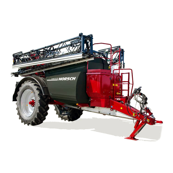
- Page 1 OPERATING INSTRUCTIONS LEEB 6 / 7 / 8 GS TRANSLATION OF THE ORIGINAL OPERATING INSTRUCTIONS READ CAREFULLY PRIOR TO STARTING UP! KEEP OPERATING INSTRUCTIONS IN A SAFE PLACE! ART.: 8090 0221 ISSUE: 09/2017...
- Page 3 HORSCH: ..............Confirmation of receipt of machinery Warranty claims become only effective when the first use of the machine is reported to HORSCH Maschinen GmbH within a week. www.horsch.com under SERVICE PARTNERBEREICH an interactive PDF form is available for down- load for this purpose (not available in all languages).
- Page 4 EG-Konformitätserklärung HORSCH LEEB Application Systems GmbH Plattlinger Straße 21, D-94562 Oberpöring erklärt hiermit in alleiniger Verantwortung als Hersteller, dass das nachfolgend genannte Produkt: Gezogene Pflanzenschutzspritze Maschine: Leeb 6 GS Typ: Leeb 7 GS Leeb 8 GS den einschlägigen grundlegenden Sicherheits- und Gesundheitsanforderungen der Richtlinien 2006/42/EG und 2009/127/EG entspricht.
-
Page 5: Foreword
We would like to thank you for the trust you have expressed in us by buying this machine. HORSCH LEEB AS will not assume liability In order to be able to use the trailed crop for any damage or malfunctions resulting from protection sprayer to your full advantage, please failure to comply with the operating instructions. - Page 6 Any information, illustrations and technical Service specifications in these operating instructions HORSCH LEEB AS wishes you to be fully are up-to-date at the time of publishing. We, at satisfied with your machine and us. any time, reserve the right for design changes,...
-
Page 7: Table Of Contents
Table of contents 1.16 safety notices on the machine ....26 Foreword ............5 1.17 Instruction sticker........26 1. Safety ............11 1.18 Safety stickers ........26 1.1 Notes on representation ......11 1.19 Position of safety stickers .....29 1.2 Qualification and training of personnel ... 11 2. - Page 8 3.20 Transport, document and safety 4.9 Nozzle body ..........86 container ..........58 4.9.1 Single nozzle body with 3.21 Document roll ........59 pneumatic control valve ....86 3.22 Pneumatic brake system ......59 4.9.2 Multiple nozzle body manual 3-fold ..86 3.22.1 Automatic load dependent brake 4.9.3 Multiple nozzle body pneumatic..87 pressure regulator (ALB) ....61 4.9.4 Multiple nozzle body manual 4-fold ..87...
- Page 9 8.3 Filling with water ........107 8.5 Spraying operation .......120 8.3.1 Filling the spraying mixture 8.5.1 Special notes for spraying operation ... 120 container through the filling port ..108 8.5.2 Adjusting the spraying height ..121 8.3.2 Direct filling / external filling (optional) ..109 8.5.3 Spraying pressure, nozzle size, 8.3.3 Filling through the filling dome ..109 placing quantity, travel speed,...
- Page 10 10. Putting into storage ......139 12. Nozzle selection........167 10.1 At the end of the spraying season ..139 12.1 General ..........167 10.2 Drainage ..........139 12.2 Procedure ...........167 10.2.1 Drainage of solution container ..139 12.2.1 With diagram and universal table ...167 10.2.2 Drainage of spraying pump...139 12.2.2 With application quantity table ..170 10.2.3 Drainage of fresh water tank..140 12.3 Pressure ranges of different nozzles ...172...
-
Page 11: Safety
1. Safety 1.2 Qualification and training of personnel 1.1 Notes on The crop protection sprayer must only be representation operated, serviced and repaired by persons who are familiar with it and have been made aware Warning notes of the dangers involved. The owner is obliged These operating instructions distinguish between to exactly specify the area of responsibility, competence and the monitoring of personnel. -
Page 12: Workplace Of The Operator
1.3 Workplace of the Follow the instructions given on the warning signs to avoid dangers. The occupational safety operator and accident prevention instructions issued by the responsible liability association are binding. The machine must solely be operated by one person and only from the driver's seat of the When driving on public roads you must strictly tractor. -
Page 13: Coupling And Uncoupling The Machine
Become familiar with all equipment and Parts actuated by external forces (e.g. ¾ ¾ control elements as well as their functions hydraulics) have crushing and shearing points! before starting work. When working on the crop protection sprayer ¾ It is prohibited to remain inside the working secure the machine with wheel chocks ¾... -
Page 14: Working With The Machine
When operating supporting devices there is a Never climb onto the moving machine! ¾ ¾ risk of injury at crushing and shearing points! Parts actuated by external forces (e.g. ¾ Be particularly cautious when coupling and hydraulics) have crushing and shearing ¾... -
Page 15: Transporting The Machine
1.6.5 Transporting the machine Match the travel speed to the prevailing ¾ conditions! When driving on public roads comply with Shift to a lower gear before driving downhill! ¾ ¾ the corresponding national road traffic Always switch off single wheel braking (lock ¾... -
Page 16: Electric System
When disconnecting ¾ excessively aged! Use only genuine hydraulic disconnect the negative pole first and the hoses from HORSCH LEEB AS! positive pole after! The utilization period of hydraulic hoses Always cover the positive battery pole with the ¾... -
Page 17: Towed Machines
¾ all fastening screws and nuts as specified by flame cutting or drilling work near brake lines! HORSCH LEEB AS GmbH! Failing to do so After setup and repair work on the brake ¾ can lead to loosing wheels and thus to the system you must generally carry out a brake machine tipping over. -
Page 18: Pto-Shaft / Propshaft
1.6.12 PTO-shaft / propshaft 1.6.13 Handling crop protection agents Persons can be caught, pulled in and seriously injured by the rotating PTO-shaft or propshaft. Follow the recommendations of the crop ¾ protection agent manufacturers in regard to Before any work on the propshaft (assembly, protective clothing. -
Page 19: Operating The Crop Protection Sprayer
¾ is approved for the respective crop protection Never open pressurized lines! ¾ agent used. Use only original spare hoses from HORSCH ¾ Do not fill crop protection sprayers with water ¾ LEEB AS, which will withstand the chemical, from open bodies of water - to protect man, mechanical and thermal loads. -
Page 20: Maintenance
Wear gloves to protect against sharp-edged manufacturer! This is ensured when using ¾ machine parts. original spare parts from HORSCH LEEB AS! Repair, maintenance and cleaning work as For the storage of gas use only nitrogen for ¾ ¾... -
Page 21: Unauthorized Conversion And Manufacture Of Spare Parts
¾ must be replaced immediately. and undercarriage Use only original HORSCH LEEB AS spare parts welding on load bearing parts ¾ and wear items, to maintain the validity of the type approval as per national and international regulations. -
Page 22: Working In The Vicinity Of High Voltage Power Lines
1.11 Working in the 1.13 Danger caused by vicinity of high voltage residual energy power lines Pay attention to the occurrence of mechanical, hydraulic, pneumatic and electric/electronic Use extra caution when working under or within residual energies on the machine. Apply the range of high voltage power lines. -
Page 23: Specified Equipment
¾ maintenance work. different compositions of crop protection agents ¾ the sole use of genuine HORSCH LEEB AS ¾ (insecticides, fungicides, herbicides etc.) in the spare parts. form of suspensions, emulsions and mixtures as... -
Page 24: Effects When Using Certain Crop Protection Agents
The materials and components used for the is free of persons. HORSCH LEEB AS crop protection sprayers are liquid fertiliser proof. -
Page 25: Personal Protective Outfit
Danger spots exist: Wear safety gloves: before you start to process crop protection between tractor and crop protection sprayer, ¾ ¾ agents, especially when coupling and uncoupling before starting work on the contaminated crop in the area of moving components. ¾... -
Page 26: Safety Notices On The Machine
1.16 safety notices on the Loading hook hook the load suspension gear machine (chains, ropes etc.) into this loading hook during loading. The towed crop protection sprayer GS is 00380880 equipped with safety and protective features. Not all danger spots on this machine can be completely safeguarded under due The CE-sign indicates that the consideration of the functionality of the machine. - Page 27 Danger caused by accidental Switch the engine off and pull out movement of the machine! the key before starting maintenance and repair work! 04002983 04002983 The pressure accumulator is Before commissioning the machine charged with gas or oil pressure. you need to read and follow Dismantle and repair only in strict the operating instructions! compliance with the instructions in...
- Page 28 Danger of burning on hot surfaces. Keep a sufficient safety distance to Keep a safe distance to hot surfaces! the slewing range of the machine! 04001453 04001454 Avoid any contact with hazardous Danger of poisoning - never climb into the tank! substances! Wear protective clothing! Danger from inhaling hazardous...
-
Page 29: Position Of Safety Stickers
1.19 Position of safety stickers... -
Page 31: Product Description
2. Product description This chapter provides a comprehensive overview of the design of the machine and designates the individual assembly groups and actuating components. You should preferably read this chapter directly on the machine. This is how you familiarise yourself with the machine. 2.1 Overview Spraying mixture container Platform... -
Page 32: Safety And Protective Features
2.2 Safety and protective features Folding boom rest for inside wing Slope compensation Folding lock Railing for working platform Parallelogram lock... -
Page 33: Fluid Circuit - Construction Elements On Machines Of The Eco Variant
2.3 Fluid circuit - Construction elements on machines of the ECO variant 1. Solution tank 19. Folding boom 2. Fresh water tank 20. Injector 3. Mechanical 5-way valve on suction side 21. Internal cleaning 4. Solution tank filling via suction 22. -
Page 34: Fluid Circuit - Construction Elements On Machines Of The Ccs Variant
2.4 Fluid circuit - Construction elements on machines of the CCS variant 1. Solution tank 21. Injector 2. Fresh water tank 22. Internal cleaning 3. Mechanical 5-way valve on suction side 23. Agitator 4. Solution tank filling via suction 24. Illuviation valve 5. -
Page 35: Fluid Circuit - Construction Elements On Machines Of The Ccs Pro Variant
2.5 Fluid circuit - Construction elements on machines of the CCS Pro variant 1. Solution tank 21. Injector 2. Fresh water tank 22. Internal cleaning 3. Electrical 5-way valve on suction side 23. Agitator 4. Solution tank filling via suction 24. -
Page 36: Supply Lines Between Tractor And Machine
2.6 Supply lines between tractor and machine Supply lines in parking position: 1. Pneumatic brake lines brake and reservoir 2. 7-pin plug for lighting 3. ISOBUS 4. Hydraulic connections pressure supply and pressureless return 5. Hydraulic connections LS-control line (Load Sensing) and support 2.7 Traffic-compliant equipment both sides:... -
Page 37: Technical Data
2.8 Technical data NOTE Payload = permissible total weight - basic weight DANGER Exceeding the permissible payload is prohibited. Danger of accident caused by unstable driving! Carefully determine the payload and thus the permissible filling of the machine. Not all filling media allow a complete filling of the machine. - Page 38 Machine type 6 / 7 / 8 GS min./max. Sections (pieces) 6 / 42 Working height (m)* 0.3 - 2.5 Pump capacity Centrifugal pump (litres/min) 1000 Machines of the CCS and CCS Pro variants ¾ Pump capacity diaphragm pump (litres/min) Machines of the ECO variant ¾...
-
Page 39: Dimensions
Data on the type plate: Fresh water capacity Chassis number Year of Spraying mixture capacity Model designation construction Made in Germany HORSCH LEEB Application Systems GmbH EC vehicle type Plattlinger Straße 21, D-94562 Oberpöring Tel. +49 (0) 9937 / 95963-0 www.HORSCH.com EG-Fahrzeugtyp Frischwasser Fgst.-Nr. -
Page 40: Permissible Total Weight And Tyres
2 9 3 7 2 9 4 7 5 6 6 2 8 5 9 9 Oberfläche / Beschichtung Allgemeintoleranzen Werkstückkanten © HORSCH LEEB Application Systems: Änderungen sind untersagt -0,3 +0,3 ..DIN ISO 2768-mK Urheberschutz: Für diese technische Unterlage... - Page 41 Permissible axle load of the fixed axle load Design rigid steered rigid steered Track [mm] 1800 - 2250 1800 - 2250 2000 - 2250 2000 - 2250 Axle load [kg] 10 000 10 000 10 000 10 000 (25 km/h) Axle load [kg] 10 000 10 000...
- Page 42 Load bearing capacity per wheel Tyres Load 25 km/h 40 km/h 50 km/h index permissible with air permissible with air permissible with air load bearing pressure load bearing pressure load bearing pressure capacity (kg) (bar) capacity (kg) (bar) capacity (kg) (bar) M i c h e l i n 176 D...
- Page 43 Load bearing capacity per wheel Tyres Load 25 km/h 40 km/h 50 km/h index permissible with air permissible with air permissible with air load bearing pressure load bearing pressure load bearing pressure capacity (kg) (bar) capacity (kg) (bar) capacity (kg) (bar) A l l i a n c e LI 170 D...
-
Page 44: Noise Development Data
2.9 Noise development data The work place related emission value (sound pressure level) is 74 dB(A), measured in operating condition with the cabin closed at the ear of the tractor driver. Measuring instrument: OPTAC SLM 5. The sound pressure level mainly depends on the vehicle used. 2.10 Required tractor equipment The tractor must meet the specified power requirements and be fitted with all necessary electric, hydraulic and brake connections for the brake system to be able to work with the machine. - Page 45 NOTE All values represent the max. required amount of oil for the respective function! Hydraulic oil in the machine: Hydraulic/gear oil OMV austromatik IGB The hydraulic/gear oil in the machine is suitable for the combined hydraulic/gear oil circuits in all common tractor brands. Tractor control units: 1x dual-acting for hydraulic support 1x pressureless return...
-
Page 46: Design And Function
3. Design and 3.2 Connections function Overview of connections 3.1 Control unit The external control terminal, filling connections and illuviation valve are arranged in travel direc- tion on the left hand side. 1 Pressure filter 2 Direct filling/external filling of solution tank (optional) 3 Suction connection for solution tank filling 4 Filling port for fresh water tank 5 Spraying mixture tank residue drain... -
Page 47: Nozzles
The nozzles are mounted on the folding boom in the tractor cabin. with a spacing of 50 cm / 25 cm. Refer to the HORSCH Terminal operating instructions for the detailed operation of the software. Furthermore, the external control terminal is... -
Page 48: Fluid Circuit - Function
3.8 Fluid circuit - function See also “Fluid circuit - construction elements” The illustration shows the fluid circuit on machines of the CCS Pro variant 1) Filling 2) Suction The externally sucked in fluid is directed in The spraying pump (a) (for machines of the ECO filling mode via the spraying pump (a) (with variant the piston diaphragm pump) draws fluid machines of the ECO variant via the piston... - Page 49 Function - continued See also “Fluid circuit - construction elements” The illustration shows the fluid circuit on machines of the CCS Pro variant 3) Spraying operation 4) Circulation In spraying operation the sucked in fluid is With the nozzles switched off, the circulation directed through the pressure filter (e) and the valve (o) is in position (2), so that the wash flow meter (f) into the nozzle line (g).
-
Page 50: Illuviation Valve
3.9 Illuviation valve 1 Hinged lid 2 Handle to swing the illuviation valve The pivotable illuviation valve is used to pour in, 3 Parallelogram arm to swing the illuviation dilute and draw in crop protection agents and valve from transport to filling position carbonyl diamide. - Page 51 Washing gun A washing gun for cleaning the illuviation tank after filling can be found on the illuviation valve. Apart from this, deposited residues can be flushed out of the canisters. 12 Filling level gauge 13 Suction opening 14 Rinsing nozzles for dilution and illuviation of crop protection agents 15 Pressure plate 16 Rotating canister flushing nozzle to flush...
-
Page 52: Spraying Pump
3.10 Spraying pump The pump has an oil-filled cavity as dry-running protection and for cooling. The crop protection sprayer is equipped with a Check the pressure in the pressure gauge of centrifugal pump for the spraying system (only ¾ the pump. for machines of the CCS Pro and CCS variant). -
Page 53: Piston Diaphragm Pump On Machines Of The Eco Variant
3.12 Piston diaphragm 3.13 Hand washing tank pump on machines of the NOTE ECO variant Fill only clean water into the hand washing Machines of the ECO variant only have a tank! ¾ piston diaphragm pump and not a centrifugal pump! WARNING The piston diaphragm pump is located in the... -
Page 54: Agitator
3.14 Agitator Please note that the use of pressure filter el- ements with 80 or 100 meshes/inch may with some crop protection agents cause the sepa- The solution tank is equipped with a hydraulic ration of biocatalysts. agitator. Special injector nozzles in the agitator If in doubt, contact the crop protection agent tube reinforce the stirring intensity. -
Page 55: External Cleaning System (Optional)
3.16 External cleaning Overview of pressure filter elements system (optional) Meshes/inch Nozzle size Mesh size [mm] NOTE from ‘03’ 0.35 The external washing facility is supplied directly by the spraying pump of the fresh water tank. ‘02’ 0.20 up to ‘015’ 0.15 WARNING Filter cleaning, see chapter Cleaning,... -
Page 56: Hydraulic Connections
3.17 Hydraulic With the external cleaning system two optional variants are available: connections 1/2" hose with hose reel and washing • WARNING Danger of infection caused by high pressure hy- draulic oil from the hydraulic system penetrating into the body! Danger of severe injuries! When coupling or decoupling hydraulic hoses make sure that the hydraulic system has been... -
Page 57: Uncoupling Hydraulic Hoses
3.18 Pulling tool (optional) 1. Actuate the control lever on the tractor mount- ed control valve to floating position (or neutral position). The drawbar hitch is intended for twin-axle trail- ers without drawbar load. 2. Clean the hydraulic plugs on the hydraulic hoses before connecting the hydraulic hoses to the tractor. -
Page 58: Lifting Points
3.19 Lifting points The machine can be fastened at the following points to secure it for transportation: Both sides at the front of the machine only for machines of the CCS Pro variant WARNING To avoid contamination of the tractor cabin, it must not be entered with used protective clothing! Protective clothing shall always be stored in the transport and safety container provided for it. -
Page 59: Document Roll
3.21 Document roll 3.22 Pneumatic brake system A document roll with bracket is located at the right machine side under the front covering. Documents about currently used crop protection NOTE agent need to be stored in it. They provide valu- able information about the content of the hopper Strict compliance with the specified mainte- and in the spraying boom for rescue personnel... - Page 60 (1) Air vessel (2) Tension straps (3) Drainage valve for condensation water (4) Test port for pressure gauge Twin-circuit pneumatic brake system Actuating button to release the pneumatic brake When uncoupling the machine from the tractor, the pneumatic brake of the sprayer automatically engages in the brake position.
-
Page 61: Automatic Load Dependent Brake Pressure Regulator (Alb)
3.22.1 Automatic load dependent 3.22.2 Connection of brake brake pressure regulator (ALB) system WARNING WARNING Danger of crushing, cutting, being pulled in, Danger of crushing, cutting, being pulled in, being caught and impact caused by incorrectly being caught and impact caused by incorrectly functioning brake system! functioning brake system! Perform a function test of the brake system... -
Page 62: Uncoupling The Brake System
3. Fasten the coupling head of the supply line WARNING (red) correctly in the red coupling on the tractor. Danger of crushing, cutting, being pulled in, be- When coupling the supply line (red) the ¾ ing caught and impact caused by accidentally supply pressure from the tractor will push rolling machine after the service brake has been out the actuating button for the releasing... -
Page 63: Drawbar
3.23 Drawbar 3.24 Automatic Ackerman steering (optional) NOTE DANGER Positively secure the coupling bolt after connect- ing the crop protection sprayer! Danger of accident caused by the machine tipping over! 2 variants are available to connect the crop Activate the Ackerman steering by selecting protection sprayer: road travel on the terminal for road and trans- port travel. -
Page 64: Adjusting The Mechanical Steering End Stop
When using different tyres or track widths, the Information on the adjustment of the electronic mechanical steering stop needs to be adjusted. steering limitation is provided in the HORSCH In addition, the max. end stops must be taught Terminal operating instructions. -
Page 65: Suspension
3.26 Suspension 3.27 Hydraulic support If the machine suspension uses air-spring bel- The hydraulically operated support supports the lows, it is equipped with automatic level adjust- uncoupled trailed sprayer. ment, regardless of the load condition. Operation takes place via a double-acting con- trol valve on the tractor. -
Page 66: Working Platform With Ladder
3.28 Working platform 3.29 Fresh water tank with ladder The fresh water tank (1) is located between the platform and the solution tank. The tank capacity Working platform with foldable access ladder to is 500 litres. reach the filling dome. Hold on to the ladder. -
Page 67: Main Control Terminal
ISOBUS-compatible terminal Touch 800 as standard feature (alternatively Touch 1200). Other ISOBUS compatible terminals may alter- natively also be used. However, this should be discussed with the HORSCH- LEEB Service Tank lid with ventilation of the fresh water tank before use. NOTE... -
Page 68: Multi-Function Handle
LED (1). Switch Coloured status LED position Yellow Green NOTE More Information on the operation and configu- ration of the multi-function handle is provided in the HORSCH Terminal operating instructions. -
Page 69: Default Assignment Of Multi-Function Handle
3.31.1 Default assignment of multi-function handle Ackerman steering “Automatic mode” Ackerman steering “ON / OFF” Left folding boom wing up * Right folding boom wing up * Left folding boom wing down * Right folding boom wing down * Steering “manual” travel direction “left” Steering “manual”... -
Page 70: Propshaft
3.32 Propshaft Use only propshafts with proper protective outfit! The propshaft locks must engage securely. Only on machines of the ECO variant. ¾ The length of the propshaft must be adjusted to the tractor; see chapter Adjusting the propshaft as well as the operating instructions for the propshaft. -
Page 71: Pto-Shaft Pump (Optional)
3.33 PTO-shaft pump The lifting gear geometry and the min./max. dis- tance over the entire lifting distance is decisive (optional) for the length of the propshaft. In case of insufficient hydraulic power of the trac- NOTE tor the PTO-shaft pump can optionally be used. Possible only for machines of the CCS Pro ¾... -
Page 72: Nightlight (Optional)
3.34 NightLight (optional) DANGER Extremely bundled light (LED spotlight) to illu- Danger of injuring during assembly! minate the spraying cones. Before performing assembly work shut down When the spraying process is switched off at the ¾ the tractor and pull off the ignition key! headland the lights are automatically cleaned by Never switch on the PTO-shaft with the en- a washing facility. -
Page 73: Pack Storage (Optional)
3.35 Pack storage (optional) An optional pack storage can be installed at the right machine side under the covering. This is provided for the secure transport of crop pro- tection agents. Pump NightLight cleaning (3) The pump is located at the undercarriage on the left machine side below the solution tank Pack storage between the pressure fitting and the travel axis... - Page 74 Clean compressor block and fan protection ¾ grille daily or when required. Carefully use compressed air for this purpose. Otherwise the compressor could overheat. Drain the water from the frame tube at least ¾ once every week. For this purpose open the drain valve slowly.
- Page 75 Troubleshooting Malfunction Possible cause Remedy Fault on hydraulic valve of compressor or Check and repair, if necessary Compressor does not start, on solenoid valve in hydraulic valve block (workshop work) even though the tractor is in Compressor switched off by ON/OFF- Switch on compressor operation switch on pressure switch...
-
Page 76: Gps Receiver (Optional)
3.37 GPS receiver Assembly (optional) CAUTION Risk of crushing from very powerful magnet on Description the base of the GPS receiver! When installing the GPS receiver, hold it firmly The GPS receiver serves to determine the exact with both hands to make sure no fingers get position of the machine. - Page 77 Information on the configuration of the GPS for installation on the crop protection ¾ receiver is provided in the HORSCH brief in- sprayer: on the carrier plate of the cross- structions GPS Setting. beam 2. Glue the double-sided self-adhesive plate (1) Technical data on the cleaned surface.
-
Page 78: Design And Function Of The Spraying Boom
4. Design and 4.1.1 BoomControl Pro (optional) Function of the Further development of the automatic folding boom guide to maintain the exact, lowest pos- Spraying Boom sible working height, even when driving with high travel speed and in highly cropped terrain. This creates the prerequisite for minimum drift. -
Page 79: Boomcontrol Modes
4.2 Folding and unfolding 4.1.2 BoomControl modes Various equipment versions are available. WARNING Depending on the mode, there are different designs. Danger of crushing, being pulled in, being caught or impact for operator and third parties BoomControl ECO may arise if third parties remain in the operat- Design with 2 or 4 sensors for height adjustment ing range of the folding boom when unfolding and slope compensation. - Page 80 For this purpose access the page Folding on the terminal. NOTE Instructions for operating the terminal are in- ¾ cluded in the supplied operating instructions! Instructions for operating the sprayer software ¾ are included in the supplied terminal operating instructions from HORSCH.
-
Page 81: Folding Variants - Folding Boom
4.3 Folding variants - folding boom Folding boom, 5-piece with reduced working width 12 m 12 m 18-24 m Folding boom, 7-piece with reduced working width 12 m and 21 m 12 m 21 m 27-30 m Folding boom, 7-piece with reduced working width 24 m 24 m 30-36 m Folding boom, 7-piece with reduced working width 27/28 m... -
Page 82: Adjusting The Spraying Height
4.4 Adjusting the spraying 4.5 Transport lock height WARNING WARNING Danger from crushing and impact for per- sons may arise if the folding boom folded Danger of crushing and impact for persons to transport position accidentally unfolds when lifting or lowering for height adjust- during travel! ment of the spraying boom! The folding boom package must be locked and... - Page 83 Folding boom rest Parallelogram interlock closed NOTE Before setting off for road travel make sure that the folding boom rests securely in the folding boom rest and both the package lock and the parallelogram lock are closed. Folding boom put down Parallelogram interlock open...
-
Page 84: Slope Compensation / Pendulum Lock
4.6 Slope compensation / 4.7 Collision protection pendulum lock The collision protection protects the folding boom against damage caused by collision with a solid obstacle. The joint mechanism enables escaping a collision in travel direction and in opposite direction. Slope compensation / pendulum lock unlocked After the escape movement the collision protec- tion will swing back to the initial position. -
Page 85: Spraying Line
4.8 Spraying line 4.8.1 Circulation system Due to the permanent circulation of the biocata- The spraying line is made of stainless steel lytic solution through the complete folding boom pipe. The nozzle control has been designed as while the sprayer is switched off, spraying fluid pneumatic single nozzle control for all versions. -
Page 86: Nozzle Body
4.9 Nozzle body 4.9.2 Multiple nozzle body manual 3-fold 4.9.1 Single nozzle body with The 3-fold nozzle body is recommended if more pneumatic control valve than only one nozzle type is used. Only the ver- tically arranged nozzle will be supplied. If a pressure of more than 4 bar is applied to the By turning the nozzle body, another nozzle is compressed air connection (4), the valve will... -
Page 87: Multiple Nozzle Body Pneumatic
4.9.3 Multiple nozzle body 4.9.4 Multiple nozzle body manual pneumatic 4-fold These multiple nozzle bodies are installed in the The 4-fold nozzle body is recommended if more form of dual or 4-fold versions. than only one nozzle type is used. Only the two In this case it is possible to switch the desired vertical nozzles will be supplied. -
Page 88: Border And Edge Nozzles, Electric (Option)
4.9.5 Border and edge nozzles, If an edge nozzle is switched on with the fol- ¾ lowing nozzle body arrangement, the main electric (option) nozzle of the outermost nozzle body is auto- matically disabled. An additional optional nozzle is mounted on 1-0 with multiple nozzle body manual 3-fold the folding boom with the following nozzle body •... - Page 89 With the following nozzle body arrangement, ¾ the border or edge nozzle is located in the outermost multiple nozzle body and is always integrated in the folding boom. • • Switching between border or edge nozzle is done with the switch-over ball valve. If an edge nozzle is enabled, the main ¾...
-
Page 90: Nozzle Assembly And Cleaning
4.10 Nozzle assembly and 4.10.2 Nozzle replacement cleaning Turn the nozzles each by approx. 45° (to end ¾ position) to remove and install them. 4.10.1 Nozzle assembly Use the delivered tool for this purpose: ¾ CAUTION CAUTION Spraying mixture running out! Use appropriate protective outfits. -
Page 91: Commissioning
5. Commissioning Do not block any actuators on the tractor, which serve the purpose of directly executing hydraulic or electric movements of components, such as e.g. folding, slewing and pushing processes. The This chapter informs you about respective movement must stop automatically the commissioning of the machine. -
Page 92: Safeguarding Tractor / Machine
5.2 Safeguarding tractor / You find these data on the type plate or in the vehicle registration papers and in the operating machine instructions for the tractor. The front axle of the tractor must always be WARNING loaded with at least 20% of the curb weight of the tractor. -
Page 93: Initial Commissioning Of The Service Brake System
5.4 Assemble the wheels These activities in particular pose danger by contact with unsecured components. Lowering of raised machine, unsecured ma- ¾ WARNING chines/machine parts. Use only approved tyres as specified in the This prevents accidental lowering: technical data. Shut down the tractor engine. ¾... -
Page 94: Transport Travels
6. Transport travels WARNING Danger of breakage during operation, in- 6.1 Safety notes sufficient stability and inadequate steering and braking ability of the tractor if used for purposes other than those intended! NOTE These hazards cause severe or even fatal ¾... -
Page 95: Shut-Off Valve
6.2 Shut-off valve CAUTION A shut-off valve is installed at the right side of In order to maintain a sufficient safety dis- ¾ the machine to lock optional steering of the axle tance to overhead lines, the total height of and lift of the parallelogram during road travel. -
Page 96: Transport Lock
6.3 Transport lock 6.3.2 Package lock The transport lock straps serve to lock the fold- WARNING ed spraying boom in transport position. They prevent accidental unfolding. Hazards from crushing and impact for persons may arise if the folding boom folded in transport NOTE position accidentally unfolds during transport travel! -
Page 97: Interlocking Of Slope Compensation
6.3.3 Interlocking of slope 6.3.4 Interlocking of parallelogram compensation The parallelogram is locked automatically as soon as the folded folding boom is in the end position Interlocking of the slope compensation takes of the rest. place automatically when the folding boom is When the folded folding boom is lifted from the folded. -
Page 98: Coupling And Uncoupling The Machine
7. Coupling and 7.1 Coupling the machine uncoupling the WARNING machine Danger of breakage during operation, insuf- ficient stability and inadequate steering and braking ability of the tractor if used for purposes NOTE other than those intended! Only connect machine to tractors which are Observe also the chapter “Safety notes”... -
Page 99: Uncoupling The Machine
WARNING NOTE Danger caused by power supply failure between Check all plug-and-socket connections (hydrau- tractor and machine caused by damaged supply lic, electric and pneumatic) for cleanliness and lines! firm seating. When coupling the supply lines, pay attention Dirty connectors will contaminate the flowing to the routing of the lines: media. -
Page 100: Manoeuvring The Uncoupled Machine
Procedure NOTE 1. Park the empty machine on a horizontal parking area with solid ground. If the air pressure inside the air vessel drops below 3 bar (e.g. because of several actuations of the 2. Engage the parking brake of the crop protec- releasing valve or leakages in the brake system), tion sprayer by means of the crank. -
Page 101: Working With The Machine
8. Working with the machine NOTE WARNING Pay attention to the separate operating in- Danger of crushing, shearing, cutting, cut- structions for the control terminal. ting off, being caught, being pulled in and impact caused by When working with the machine pay attention accidental lowering of lifted, unsecured ¾... -
Page 102: Preparing The Spraying Operation
8.1 Preparing the spraying WARNING operation Danger caused by accidental contact with crop protection agents / spraying mixture! NOTE Wear personal protective outfit Basic prerequisite for the proper application when preparing the spraying mixture. ¾ of crop protection agents is the proper func- when cleaning / replacing spray nozzles. -
Page 103: Preparing The Spraying Mixture
8.2 Preparing the spraying Generally clean the crop protection sprayer ¾ before placing another crop protection agent. mixture Flushing nozzle line and nozzles: ¾ with each nozzle change • DANGER before the installation of other nozzles • before turning the manual three-fold / four- •... - Page 104 General procedure NOTE 1. Determine the required water and preparation application quantity as per instructions for use Besides the generally valid information listed for the crop protection agent. hereunder, you should also follow the prod- uct-specific procedures described in the instruc- 2.
-
Page 105: Calculating Filling / Refill Quantities
8.2.1 Calculating filling / refill Example 2: Addition of product, area quantities The following is known: Rated tank volume 1000 l Residual quantity in tank 200 l NOTE Required water 500 l/ha Recommended concentration 0.15 % l/l or kg/l Use the “Filling table for residual areas” (chapter 8.2.2) to calculate the required refill quantity for Question 1: the last spraying mixture container filling. -
Page 106: Filling Table For Residual Areas
8.2.2 Filling table for residual areas NOTE Use the “Filling table for residual areas” to ¾ calculate the required refill quantity for the last spraying mixture container filling. Subtract the residual quantity in the spraying ¾ line from the calculated refill quantity! See also chapter “Spraying line”. -
Page 107: Filling With Water
8.3 Filling with water Never exceed the permissible payload of ¾ the crop protection sprayer when filling the spraying mixture container. NOTE Pay attention to the specific weight of the fluid ¾ to be filled in. When filling, pay attention to the permissible payload of your crop protection sprayer! When filling keep an eye on the level gauge ¾... -
Page 108: Filling The Spraying Mixture Container Through The Filling Port
8.3.1 Filling the spraying mixture 7. Close the filling valve. container through the filling port 8. Uncouple the suction hose. 9. Close the connection with the cap. Pay attention to the applicable regulations for filling the spraying mixture container through the suction hose from open water taps. -
Page 109: Direct Filling / External Filling (Optional)
5. By switching on the PTO-shaft the piston The procedure for direct filling is the same ¾ diaphragm pump is activated and the filling for all machine variants! process starts. 1. Connect the filling hose. 6. Observe the filling level of the solution tank 2. -
Page 110: Filling The Fresh Water Tank Through The Filler Connection
NOTE NOTE The dome screen must be checked daily and Fill the fresh water tank only with clear cleaned as necessary! water, never with crop protection agent A cleaning nozzle can be retrofitted to facilitate or spraying mixture! cleaning of the dome screen. Filling connection for fresh water tank Filling dome 1. -
Page 111: Flushing In Preparations
8.4 Flushing in Flush the respective preparation through the illuviation valve into the water of the spraying preparations mixture container. A difference is in this case made between the illuviation of fluid and pow- 8.4.1 Illuviation valve dery preparations or carbonyl diamide. DANGER Wear appropriate protective clothing for the illuviation flush in the preparations. -
Page 112: Flushing In Liquid Preparations During The Filling Process On Machines Of The Ccs Pro Variant
8.4.2 Flushing in liquid preparations during the filling process on machines of the CCS Pro variant 1. Enter the desired container content in the terminal 2. Connect the suction hose to the filling con- nection. At the beginning of the filling process the water sucked in through the suction hose is applied to the illuviation valve. -
Page 113: Flushing In Liquid Preparations During The Filling Process On Machines Of The Ccs Variant
8.4.3 Flushing in liquid 12. Pre-clean the illuviation valve with the closed circuit flushing (d). preparations during the filling 13. Open the switch-over ball valve and have process on machines of the CCS the contents sucked off. variant 14. Close the switch-over ball valve (e) again. 1. -
Page 114: Flushing In Liquid Preparations During The Filling Process On Machines Of The Eco Variant
8.4.4 Flushing in liquid 12. Open the switch-over ball valve and have the contents sucked off. preparations during the filling 13. Close the switch-over ball valve (e) again. process on machines of the ECO 14. Set the ball valve on the pressure side again variant to Fill solution tank . -
Page 115: Flushing In Liquid Preparations For Full Or Partly Filled Solution Tank On Machines Of The Ccs Pro Variant
8.4.5 Flushing in liquid 8.4.6 Flushing in liquid preparations for full or partly preparations for full or partly filled solution tank on machines filled solution tank on machines of the CCS Pro variant of the CCS variant 1. Open the lid on the illuviation valve. 1. -
Page 116: Flushing In Liquid Preparations For Full Or Partly Filled Solution Tank On Machines Of The Eco Variant
14. Set the ball valve on the suction side again 10. Open the switch-over ball valve and have to Solution tank . the contents sucked off. 15. Set the ball valve on the pressure side to 11. Clean the illuviation valve with the washing Agitator . -
Page 117: Illuviation Of Powdery Preparations And Carbonyl Diamide On Machines Of The Ccs Variant
8. Clean the illuviation valve with the washing 9. Fill the preparation quantity calculated and gun. measured for filling the tank into the illuvia- tion valve. 9. Close the switch-over ball valve (e) again. 10. Close the switch-over ball valve (e) after 10. -
Page 118: Pre-Cleaning The Canister With Spraying Mixture
8.4.11 Pre-cleaning the canister 1. Fill the spraying mixture container with approx. 500 litres of water. with spraying mixture 2. Set the ball valve on the suction side to Solution tank . 3. Set the ball valve on the pressure side to illuviation valve. -
Page 119: Cleaning The Canister With Fresh Water
8. For machines of the CCS Pro variant: De- NOTE activate the Recirculate fresh water function and switch off the illuviation valve on the terminal. Water or chemical emerges from the canister For machines of the CCS variant: Deacti- flushing nozzle when the pressure plate is vate the pump on the external control terminal pressed down. -
Page 120: Spraying Operation
Teach procedures must be carried out by Strictly adhere to the required application ¾ ¾ quantity [l/ha] during spraying operation, HORSCH service staff. to achieve an optimal treatment success In case of deviations between the actual and • ¾ the displayed distance calibrate the position with this crop protection measure. -
Page 121: Adjusting The Spraying Height
8.5.2 Adjusting the spraying The higher the spraying pressure, the smaller the drop diameter of the sprayed spraying mix- height ture. The smaller droplets are subject to higher, undesired windward drift! WARNING Increasing the spraying pressure also in- ¾ creases the placing quantity. Danger of crushing and impact for persons Decreasing the spraying pressure also staying in the danger zone when lifting or... -
Page 122: Spraying
For more information on the adjustment of Use of so-called antidrift (AD) nozzles or injec- ¾ ¾ parameters, refer to the HORSCH Terminal tor (ID) nozzles (nozzles with a high proportion operating instructions. of coarse drops). Follow the distance instructions for the corre- ¾... -
Page 123: Spraying With 25 Cm Nozzle Spacing And Reduced Target Area Distance
8.5.6 Spraying with 25 cm nozzle NOTE spacing and reduced target area distance Drainage output can be controlled with the ball valve (a). The risk of windward drifting can be consid- If the valve is fully open, the spraying pump ¾... -
Page 124: Residual Quantities
8.6 Residual quantities 8.6.2 Eliminating residual quantities A differentiation is made between two types of residual quantities: NOTE Excess residual quantity after the end of ¾ spraying operation, e.g. resulting from errors Make sure that the residual quantity in the in the calculation of the application quantity, spraying line will be sprayed out in the form of in filling quantity or in spraying operation. -
Page 125: Draining Of Technical Residual Quantities On Machines Of The Ccs Pro Variant
8.6.3 Draining of technical 8.6.4 Draining of technical residual quantities on machines residual quantities on machines of the CCS Pro variant of the CCS variant A port is provided under the spraying mixture A port is provided under the spraying mixture container for draining the technical residual container for draining the technical residual quantity. -
Page 126: Draining Of Technical Residual Quantities On Machines Of The Eco Variant
8.6.5 Draining of technical 8.6.6 Diluted residual quantities residual quantities on machines Perform the dilution and spraying out of residual of the ECO variant quantities from the spraying mixture container after the end of spraying operation as follows: A port is provided under the spraying mixture container for draining the technical residual Procedure quantity. -
Page 127: Draining The Fresh Water Tank
8.7 Draining the fresh Diluting the residual quantity with ma- chines of the ECO variant: water tank 1. Set the ball valve on the suction side to Fresh water tank . 2. Set the ball valve on the pressure side to Agitator . -
Page 128: Faults
8.8 Faults WARNING Danger of crushing, shearing, cutting, cutting off, being caught, winding up, being pulled in and impact caused by accidental lowering of lifted, unsecured machine parts. ¾ accidental starting and unintended rolling of the tractor/machine combination. ¾ Secure the tractor combination against unintended starting and accidental rolling away before faults on the machine can be rectified. -
Page 129: Sprayer Cleaning, Maintenance
Replace defective protective features with ¾ new ones. Use only HORSCH LEEB original parts. DANGER Strictly comply with all safety notes when ¾ carrying out maintenance, repair and service... - Page 130 Use only original HORSCH-LEEB AS spare ¾ parts (see also chapter “Spare parts and wear items as well as auxiliary materials”). T h e f o l l o w i n g i s g e n e r a l l y...
-
Page 131: Cleaning
9.1 Cleaning Cleaning with high pressure cleaner / steam jet CAUTION NOTE Contamination with crop protection agents. Strictly use protective outfit when cleaning Do not clean new machines with a steam jet the crop protection sprayer! See chapter or high pressure cleaner. “Working with the machine”. -
Page 132: Ccs - Continuous Inside Cleaning (Continuous Cleaning System)
9.1.1 CCS - Continuous inside Cleaning the crop protection sprayer cleaning (Continuous Cleaning System) NOTE Continuous inside cleaning is only possible ¾ Regular cleaning of the crop protection sprayer is with machines of the CCS and CCS Pro a prerequisite for proper maintenance and eases variants. -
Page 133: Cleaning The Filters
9.1.2 Cleaning the filters 1. Switch off the folding boom circulation. 2. Close the ball valve for pressure output. A ring spanner for work on the pressure and 3. Drain the filter. Open the valve for this suction filters is supplied with the machine. purpose. - Page 134 Machines of the CCS Pro variant: The suction filter of the piston diaphragm pump is located below the fresh water tank. To this 1. Start the Filter cleaning function on the end, fold the covering at the bottom of the external control terminal.
-
Page 135: Cleaning The Sprayer With The Tank Empty
9.1.3 Cleaning the sprayer with Main cleaning on machines of the CCS variant: the tank empty 1. Empty the solution tank completely. NOTE 2. The fresh water tank must be filled with at least 300 litres of water. The initially forced out residual quantity 3. - Page 136 Washing program on machines of the Washing program on machines of the CCS Pro variant: CCS variant: 1. Fill the solution tank with approx. 100 l of 1. Fill the fresh water tank with approx. 100 l water. of water. 2.
-
Page 137: Cleaning The Sprayer With The Tank Filled
9.1.4 Cleaning the sprayer with Washing program on machines of the ECO variant: the tank filled 1. Fill the fresh water tank with approx. 100 l of water. NOTE 2. Set the ball valve on the suction side to Fresh The initially forced out residual quantity water tank . -
Page 138: Folding Boom Cleaning With "Air Valve" (Option)
Procedure for machines of the CCS 7. Activate the “Air Valve” function, in order to clean the folding boom with air (optional). variant: 8. Switch off the PTO-shaft. 1. Switch off the nozzles. 9. Set the ball valve on the suction side to 2. -
Page 139: Putting Into Storage
HORSCH sales partner in due time. Your Only for machines of the CCS Pro and CCS ¾ HORSCH sales partner will be in a much better variant! position to execute the maintenance service and Release the drain plug and allow all fluid to run possibly necessary repairs outside the season. -
Page 140: Drainage Of Fresh Water Tank
10.2.3 Drainage of fresh water Empty the hand washing tank. Open the drain ¾ plug on the bottom of the tank for this purpose tank and then close it again. 1. Remove the cap on the connection for fresh water filling and open the pertaining ball valve. - Page 141 NOTE Refer to the supplied HORSCH Terminal operating instructions (Chapter 7) for the further procedure of readying the sprayer system for winter storage.
- Page 142 NOTE NOTE Refer to the supplied HORSCH Terminal Refer to the supplied HORSCH Terminal operating instructions (Chapter 7) for the further operating instructions (Chapter 7) for the further...
-
Page 143: Before The New Season
10.4 Before the new Clean the spraying system thoroughly with ¾ fresh water. This is the only way of ensuring season that no more antifreeze mix is present in the sprayer. Before the start of the new season the machine Machines of the CCS Pro variant: Let should be thoroughly examined. -
Page 144: Maintenance And Care Plan
Folding boom / parallelogram Visual inspection of folding joints for zero clearance, apparent faults and wear. In case of play or lose components, have faults corrected by HORSCH Customer Service. Suction filter, pressure filter Cleaning, flushing Lubrication points Lubricate according to lubrication plan... - Page 145 Quarter annually / 200 operating hours Component Maintenance work Workshop work Brake Leak test Check pressure in compresses air vessel Check the brake cylinder pressure Brake cylinder safety check Joints on brake valves, brake cylinders and brake linkages Brake adjustments on linkage control Inspection of brake lining Inspection of parking brake Bowden cable...
-
Page 146: Lubrication Instructions
11.1 Lubrication Brand Lubricant designation Extreme working conditions instructions ARAL Aralub HLP 2 FINA FINA Marson EPL-2 NOTE ESSO ESSO Beacon EP 2 Lubricate all grease nipples (keep seals ¾ SHELL Tetinax AM clean). Lubricate the lubrication points on the middle ¾... -
Page 147: Overview Of Lubrication Points Middle Section
11.1.1 Overview of lubrication Both sides 4 lubrication points each. ¾ points middle section Lubricate every 50 operating hours! ¾ Both sides 6 lubrication points each. ¾ Lubricate every 50 operating hours! ¾ Middle section 1 lubrication point ¾ Lubricate every 50 operating hours! Parallelogram ¾... - Page 148 2 lubrication points. 1 lubrication point ¾ ¾ Lubricate every 50 operating hours! Lubricate every 50 operating hours! ¾ ¾ Pendulum lock 1 lubrication point ¾ Pendulum lock cylinder Lubricate every 50 operating hours! ¾ 2 lubrication points ¾ Lubricate every 50 operating hours! ¾...
-
Page 149: Overview Of Lubrication Points Spraying Boom
11.1.2 Overview of lubrication Both sides 2 lubrication points each. ¾ points spraying boom Lubricate every 50 operating hours! ¾ Both sides 5 lubrication points each. ¾ Lubricate every 50 operating hours! ¾ Inside wing / centre wing Both sides 1 lubrication point each. ¾... -
Page 150: Overview Of Lubrication Points Basic Machine
11.1.3 Overview of lubrication Both sides 2 lubrication points each. ¾ Lubricate every 50 operating hours! points basic machine ¾ Hydraulic support 3 lubrication points ¾ Lubricate every 100 operating hours! ¾ Centre wing / outside wing Both sides 2 lubrication points each. ¾... - Page 151 Motion link bearing Ball socket Both sides 1 lubrication point each. 1 lubrication point ¾ ¾ Lubricate every 100 operating hours! Lubricate every 100 operating hours! ¾ ¾ PTO-shaft pump (optional) 1 lubrication point ¾ Steering arm bearing, steering cylinder Lubricate every 100 operating hours! ¾...
-
Page 152: Drawbar
11.2 Drawbar Propshaft (Machines of the ECO variant) 4 lubrication points ¾ Lubricate every 50 operating hours! DANGER ¾ Risk of accident when driving with damaged drawbar! For reasons of road safety replace a damaged drawbar immediately with a new one. Repairs must only be carried out in the manu- facturing plant. -
Page 153: Ball-And Socket-Coupling
11.4 Ball-and socket-coupling Maintenance location Work instructions Interval Ball-and-socket coupling Before connecting: Clean ball and spherical cap. daily Replace the foam ring if damaged and/or heavily soiled. daily Place the foam ring. daily Check ball and spherical cap for wear. The wear limit has 40 h been reached when the gauge rests fully on the ball or enters the spherical cap. -
Page 154: Axle And Brake
11.5 Axle and brake 11.5.1 General visual inspection WARNING NOTE A general visual inspection of the brake In order to achieve optimal braking characteristic system must be performed! and minimal wear of brake linings we recom- mend the performance of a drawing adaptation The following criteria must be checked between tractor and towed sprayer. -
Page 155: Axle Adjustment (Workshop Work)
11.5.2 Axle adjustment (workshop work) Below, the values for adjusting toe-in, straight position and camber on the axle are listed. WARNING Danger of crushing, shearing, cutting, cutting off, being caught, wound up, pulled in, caught and knocked by accidental starting and rolling away of the tractor - machine combination. Secure both tractor and crop protection sprayer against accidental starting and unintended rolling before you start working on the machine. -
Page 156: Checking The Wheel Hub Bearing Play (Workshop Work)
11.5.3 Checking the wheel hub 11.5.4 Replacing the grease of the bearing play (workshop work) wheel hub bearing WARNING WARNING Danger of crushing, shearing, cutting, cutting off, Danger of crushing, shearing, cutting, cutting off, being caught, wound up, pulled in, caught and being caught, wound up, pulled in, caught and knocked by accidental starting and rolling away knocked by accidental starting / rolling away of... -
Page 157: Brake Lining Inspection
11.5.5 Brake lining inspection 7. Slightly grease the bearing seats and assem- ble all parts in reverse order. Open the inspection opening for checking the 8. Carefully force on the parts to a tight fit with brake lining thickness by folding the rubber tab the help of pipe bushings avoiding cocking open. -
Page 158: Air Vessel
11.5.7 Air vessel 11.5.8 Test instructions for twin- line brake system (workshop work) NOTE The air vessel must be drained daily! 1. Leak test Check all ports, pipe, hose and screw con- ¾ nections for leak tightness. Pull the drain valve (3) until water stops running out from the air vessel through the valve. -
Page 159: Tyres / Wheels
The difference in tyre pressure between the Use only the tyres and rims stipulated by tyres on one axle must not exceed 0.1 bar. ¾ HORSCH LEEB. During fast travelling or hot ambient tempera- Repair work on tyres must only be carried out ¾... -
Page 160: Assembling Tyres (Workshop Work)
11.6.2 Assembling tyres (workshop work) WARNING Danger to life caused by crushing and impact in case of unprofessional or incorrect operation. Instruct persons to leave the working and danger zone when working on the machine! NOTE Perform a wheel change only with profound ¾... -
Page 161: Maintenance - Hydraulics
Replace hydraulic hoses if damaged or ex- ¾ cessively aged! Use only original hydraulic hoses from HORSCH LEEB AS! NOTE Additional specifications of the hydraulic system NOTE (circuit diagrams, etc.) can be obtained from the HORSCH service department. -
Page 162: Identification Of Hydraulic Hoses
11.7.1 Identification of hydraulic 11.7.3 Inspection criteria for hoses hydraulic hoses Hydraulic hoses must be replaced after 6 years. NOTE For this purpose pay attention to the manufac- turing date on the hose line (year/month) and The followin g inspection criteria must be ob- on the hose (quarter/year)! served in the interest of your own safety and to reduced environmental damages! -
Page 163: Assembly And Disassembly Of Hydraulic Hoses
NOTE NOTE When connecting a hydraulic hose to moving Use only original spare hoses from HORSCH parts, the length of the hose must be dimen- LEEB AS. sioned in such a way that over the total move-... -
Page 164: Calibrating The Flow Meter
The placed quantity is too high, the value under for more information on the adjustment of parameter 457 therefore needs to be corrected. parameters, refer to the HORSCH Terminal operating instructions. New value (pulses/100 l): 2,100 x 0.973 = 2,043... -
Page 165: Notes On Crop Sprayer Test
11.9 Notes on crop 4. Machines of the CCS Pro variant: Switch on the circulation on the terminal. Adjust the sprayer test rotational speed of the tractor so the pump runs at full capacity. Sprayer testing must only be carried out by Machines of the CCS variant: Set the ball authorized bodies. -
Page 166: Flow Meter Test
7. Establish the hose connection again on (order number 36960072) can be ordered the flow meter on the middle section of the from HORSCH. machine. Ensure a correct and watertight connection! 1. Disconnect the hose union to the flow meter on the middle section. -
Page 167: Nozzle Selection
12. Nozzle selection 12.2 Procedure The tables apply for 50 cm nozzle spacing. ¾ Nozzle sizes and colour coding acc. to NOTE ¾ ISO 10625 For the selection and use of nozzles you should also follow the data and recommendations of the 12.2.1 With diagram and universal respective nozzle manufacturer! table... - Page 168 Diagram (a) with example...
- Page 169 Application quantity l/ha Nozzle size Nozzle output l/min Travel speed km/h Pressure bar Travel speed km/h Pressure bar Universal table (b) for crop protection sprayers with 50 cm nozzle spacing (with example) The values apply for water at 20 °C, pressure measured directly at the nozzle. Check the values with a measuring vessel before the start of application.
-
Page 170: With Application Quantity Table
12.2.2 With application quantity The application quantity table is also affixed to the machine. table For machines with the CCS Pro variant it is 1. Determine application quantity and travel located in the storage bin next to the external speed. control terminal. - Page 171 Placing quantity in l/ha at km/h Placing quantity in l/ha at km/h Type Pressure Type Pressure l/min l/min Colour Colour orange brown -015 green grey white yellow -025 lilac black turquoise blue violet bright-blue Universal table for crop protection sprayers with 50 cm nozzle spacing (with example) The values apply for water at 20 °C, pressure measured directly at the nozzle.
-
Page 172: Pressure Ranges Of Different Nozzles
12.3 Pressure ranges of different nozzles Nozzle type Nozzle size Permissible pressure range [bar] min. pressure max. pressure LU / XRC - nozzles LU / XRC - nozzles LU / XRC - nozzles LU / XRC - nozzles 04 - 08 AD / DG / TT all sizes all sizes... -
Page 173: Liquid Fertiliser Operation
13. Liquid fertiliser Only use the black bayonet nuts for all the following 3-jet nozzles. operation Various 3-jet nozzles and their fields of application (at 8 km/h) At present there are mainly two different types 3 - jet - yellow 50 - 80 l/ha (AHL) of liquid fertiliser available: 3 - jet - red... -
Page 174: Conversion Table For Spraying Liquid Fertiliser Ahl
13.1 Conversion table for spraying liquid fertiliser (Ammonium nitrate - carbonyl diamide solution) NOTE When filling pay attention to the different densities [kg/l] of the individual fluids and the permissible payload of the crop protection sprayer! Sol. N Sol. N Sol. -
Page 175: Waste Disposal
Attention must be paid to all valid regulations. Decommissioning and waste disposal must only be carried out by operators who have been trained by HORSCH. Contact a waste disposal company, if this should be necessary. -
Page 176: Appendix
Appendix Tightening torque NOTE The tightening torques only serve as guidelines and are generally valid. Actual data given at the • corresponding points in the operating instructions have priority. Screws and nuts must not be treated with lubricants, since this would change the friction value. •... - Page 177 Inch screws Tightening torques - inch screws in Nm Screw Strength 2 Strength 5 Strength 8 diameter No marks on head 3 marks on head 6 marks on head Inch Coarse thread Fine thread Coarse thread Fine thread Coarse thread Fine thread 12.2 13.5...
-
Page 178: Adjusting The Propshaft
Adjusting the propshaft Mark the inner protection half of the propshaft. ¾ In the shortest operating state the distance to the safety funnel must be at least 40 mm: Determine the operating lengths Connect the machine to the tractor. ¾ Position machine and tractor toward each ¾... -
Page 179: Shortening The Propshaft
Shortening the propshaft Unhook the elastic element with a suitable tool: Unlock the safety funnel with a suitable tool, ¾ e.g. a screwdriver: Pull off the safety funnel: ¾ Twist the elastic element and the outer pro- ¾ tective tube against each other to unlock it: Pull off the inner protective tube: ¾... - Page 180 Slide the sealing ring on the profile tube and ¾ fasten it with two screws: Outer protective tube Slide the sealing ring in place Propshafts with sealing ring ¾ Remove the screws on the sealing ring and remove the sealing ring from the outer pro- tective tube: Fasten the sealing ring Slide the inner protective tube onto the profile tube:...
- Page 181 Slide the outer protective tube together with the Tighten the mounting screws: ¾ ¾ elastic element fully onto the other profile tube: Hook in the elastic element again using a ¾ suitable tool: Position of outer protective tube - not engaged Twist the elastic element and the outer pro- ¾...
-
Page 182: Index
Index Ackerman steering 63 Calibrate the flow meter 164 Acknowledgement of receipt 5 Camber 155 Actual volume 37 Canister flushing 50,118,119 Adjusting rod 71 Carbonyl diamide 116,117 Adjust the steering end stop 64 Care 130 Agitator 38,54,111,121,122 Central control 38 Air pressure 41,144,159 Centrifugal pump 38,52. - Page 183 Data sheets 21 Flange 41 Decommissioning 175 Floating position 57 Density 107 Flow meter 120,145 Description 31 Fluid 48. ⇨ Wash Diaphragm 90 Fluid circuit 33,34,35,48 Diaphragm valve 90 Flushing in preparations 111 Dilution 126 Foam 107 Dimensions 39 Folding and unfolding 79 Direct filling 46,109 Folding boom 37,46,144,145 disconnection (brake system) 62...
- Page 184 Ignition key 14,15,92 NightLight 72 Illuviation 116,117. ⇨ Filling Nozzle assembly and cleaning 90 Illuviation valve 31,46,50,111,112,113,114,11 Nozzle body 86 5,116,117,118,119 Nozzle control 85 Information sticker 26 Nozzle filter 55 Initial commissioning, brake system 93 Nozzle opening 54 Inspection of brake lining 157 Nozzle replacement 90 Intended use 22 Nozzles 38,47,54,120,144,145,167,173...
- Page 185 PTO-shaft 18,72,109,114,116,118,137 Solution tank 54. ⇨ Spraying mixture container PTO-shaft pump 71,92,151 Sound pressure 44 Public road 12 Sound pressure level 44 Pump 38,44. ⇨ Spraying pump Spare parts 130 Pump capacity 38,44 Speed 15,38,120,167,170 Pump capacity test 165 Sprayer adjustment 38 Punched screen 54 Spraying 122 Putting into storage 139...
- Page 186 Tension straps 60 Terminal 79,102,112,120,122 Warning 107 Test braking 93 Warning notes 11 Test port 60 Warranty 5,130 Tightening torques 176 Warranty claim processing 6 Toe-in 155 Washing facility 72 Tool bracket 58 Washing gun 50,51,56,112,113,114 Torques 176 Waste disposal 22,130,175 Total length 37 Water 18 Total weight 40...
- Page 188 All details on technical specifications and pictograms are approximate and for information only. Subject to technical product revisions. HORSCH LEEB Application Systems GmbH Tel.: +49 9937 95963-0 Plattlinger Straße 21 Fax: +49 9937 95963-66 94562 Oberpöring E-Mail: info.leeb@horsch.com www.horsch.com...
Need help?
Do you have a question about the Leeb 8 GS and is the answer not in the manual?
Questions and answers