
Related Manuals for horsch Titan 34 UW


Summary of Contents for horsch Titan 34 UW
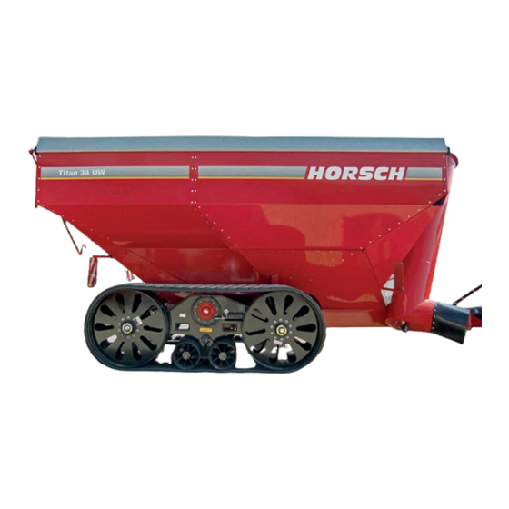
- Page 1 Operating Instructions Titan 34 UW Art.: 80060207 en Read carefully prior to starting up! Issue: 08/2014 Keep operating instructions in a safe place!
- Page 2 Designation of machine: Transport device Machine type: Titan 34 UW from serial no. 27031499 this declaration refers to, conforms with all relevant fundamental health and safety requirements of the EC directive 2006/42/EC. For proper implementation of the heath and safety requirements mentioned in the EC-directive,...
- Page 3 I hereby confirm receipt of the operating instructions for the above mentioned machine. I have been instructed by a HORSCH service technician or authorised dealer in the operation and functions of the machine, as well as in the safety requirements.
- Page 5 ..............Road: ..............Town/City: ..............Tel.: ..............Customer No.: Retailer: ..............Address of HORSCH: HORSCH Maschinen GmbH 92421 Schwandorf, Sitzenhof 1 92401 Schwandorf, Postbox 1038 Tel.: +49 (0) 9431 / 7143-0 Fax: +49 (0) 9431 / 41364 E-mail: info@horsch.com Customer No.: HORSCH: ..............
-
Page 6: Table Of Contents
Installation ............16 Tensioning the track belt ......37 Relieving the track belt ......37 Technical data ..........17 Type plate .............18 Brake system ..........38 Titan 34 UW ..........19 Brake system for caterpillar undercarriage ...40 Calculating the ballasting......20 Pneumatic actuation ........40 Hydraulic actuation ........40 Design............22 Overview............22... - Page 7 Calibrating the scales ........52 Running a self-test ........52 Calibration ..........52 Installation ............54 Wiring of weighing equipment ....55 Trouble shooting ...........56 Maintenance overview Titan 34 UW .....58 Lubrication points .........60 Gearbox oil change ........61 Waste disposal ...........62 Tightening torques ........63 Index ............65...
-
Page 8: Introduction
DANGER the safety notices! Highlights a danger that will lead to death or HORSCH will not assume liability for any dam- severe injury, if it is not avoided. age or malfunctions resulting from failure to comply with the operating instructions. -
Page 9: Service
Service Consequential damage The machine has been manufactured by The company HORSCH would be pleased, if HORSCH with greatest care. However, despite your machine and our services would meet your the intended use deviations in placement quan- expectations. tity up to total failure may be caused by e.g.:... -
Page 10: Safety And Responsibility
Safety and Spare parts Genuine spare parts and accessories from responsibility HORSCH have been specially designed for this machine. Spare parts and accessories which are not de- The following warnings and safety instructions ap- livered by us, have not been tested or approved ply to all sections in these operating instructions. -
Page 11: Qualification Of Personnel
The person has understood the operating ¾ service personnel from HORSCH. This refers to instructions and is able to implement the in- the following activities: formation given in the operating instructions Loading and transport accordingly. -
Page 12: Personal Protective Outfit
Do not exceed the permissible axle loads, tyre after receiving instructions by employees of the carrying capacities and total weights, in order to authorized dealer or a HORSCH employee. ensure sufficient steering and braking capabili- The machine registration form must be com- ties. - Page 13 Damage to the machine Hydraulic system Damage to the machine can impair the op- The hydraulic system is under high pressure. erational safety of the machine and cause ac- Hydraulic oil escaping under pressure can pen- cidents. This can lead to severe or even fatal etrate the skin and cause serious injuries.
- Page 14 If the technical limiting values of the machine workshop or by an operator, who has been are not complied with, the machine may get specially trained by HORSCH. damaged. This can lead to accidents with severe or even fatal physical injuries.
-
Page 15: Fertiliser And Dressed Seed
Fertiliser and dressed Use in the field seed DANGER Inappropriate handling of fertiliser and dressed No passengers are allowed to ride on the seed can cause poisoning and death. machine! Follow the information given in the safety ¾ data sheet of the manufacturer. If necessary Check the area around the machine (for chil- ¾... -
Page 16: Retrofits
Structural changes and extensions must only ¾ maintenance plan, see chapter “Care and be made in an authorized workshop or by an maintenance”. operator who has been trained by HORSCH. Only perform the work described in these ¾ Comply with country specific instructions fr ¾... -
Page 17: Danger Zone
Danger zone Failing to pay attention to the danger zone can The area marked red indicates the danger zone of the machine: result in severe or even fatal physical injuries. Do not stand under lifted loads. Lower such ¾ loads to the ground first. Instruct persons to leave the danger zone ¾... -
Page 18: Safety Stickers
Safety stickers Safety stickers on the machine warn of en- Clean soiled safety stickers. ¾ dangerments at dangerous points and are an Damaged or illegible safety stickers must be ¾ important part of the safety equipment of the replaced immediately. machine. - Page 19 Position of safety stickers (depending on equipment) 00380135 00380054 00380055 00383112 00380252...
-
Page 20: Commissioning
Commissioning Installation Instruction of the operator and initial installation Higher danger of accidents during commission- of the machine will be carried out by our service ing. Please pay attention to the notes in the engineers or distributors. corresponding chapters. Any preceding use of the machine is Delivery prohibited! The machine with implements is normally de-... -
Page 21: Technical Data
Technical data Titan 34 UW Length (m) 8.26 Width - axle extended (m) 3.56 Transport width wheel / caterpillar undercarriage (m) 3.00 / 3.50 Transport height (m) 4.00 Height with auger folded out (m) 5.78 Filling height hopper side / middle (m) 3.48 / 3.60 Overloading height - tyres / caterpillar undercar- 4.04 / 4.60... -
Page 22: Type Plate
The permissible transport heights and transport width for transport on public roads may differ from country to country. Comply with the national approval regulations. Type plate HORSCH Maschinen GmbH The type plate with the CE-mark is located on Sitzenhof 1, D-92421 Schwandorf Tel. -
Page 23: Titan 34 Uw
Titan 34 UW 8990... -
Page 24: Calculating The Ballasting
Calculating the ballasting Required data: The permissible total weight, the permissible axle loads and the load bearing capacity of the tyres must not be exceeded when mounting or hitching up implements. The front axle of the tractor must always be loaded with at least 20 % of the curb weight of the tractor. - Page 25 1. Calculation of minimum front ballasting 4. Calculation of the actual total weight with rear implement: • (c + d) - T • b + 0.2 • T • b Enter the result of the calculated total weight and a + b V min the permissible total weight from the operating instructions of the tractor into the table.
-
Page 26: Design
Design Overview Titan 34 UW The Titan 34 UW is particularly suitable for har- 1 Access steps vesting to maximize the power of the mowing 2 Hopper and threshing chain. 3 Lighting It is characterized by its large loading capacity... -
Page 27: Hydraulic System
"Safety and prevention of accidents"! During swinging operations slow down the control unit before the machine com- ponents reach the end stop. Hydraulics Titan 34 UW 1 Control unit 2 Hydraulic coupling 3 Hydraulic cylinder for auger 4 Hydraulic cylinder for sliding axle... -
Page 28: Lighting
Lighting Notes on operation on the machine Identification of hydraulic hoses The symbol is always found on the hose requiring pressure to bring the machine to transport posi- tion (raising, folding, etc.). Support up / down 00110681 00110682 Fold unloading auger 00110681 00110682 00110687... - Page 29 Stickers Check the tyre pressure at regular inter- Loading hook; vals, adapt if necessary - see maintenance hook the sling gear (chains, ropes etc.) into overview. this loading hook during loading! 00380880 Retighten the wheel nuts / wheel bolts Parking position spring accumulator after 50 km or 10 hours.
- Page 30 Titan axle (only for France) Retract sliding axle for road transportation. (only for France)
-
Page 31: Operation
Operation Install the PTO-shaft only with the engine stopped and the PTO-shaft switched off. Use only PTO-shafts with proper safety Whenever working on the machine pay protections! attention to the associated safety notes The PTO-shaft locks must click into place. in the chapter "Safety and prevention of accidents"! Working length... -
Page 32: Hitching Up And Transport Position
Hitching up and transport position DANGER There is a possibility that persons may become crushed and severely injured between machine and tractor! Instruct persons to leave the area between trac- tor and machine. Hitching up Hitch the machine up to the tractor. ¾... -
Page 33: Parking
Parking Hopper emptying The reloading wagon should be parked in a WARNING shed or under a roof so that no moisture can When unfolding the auger in the vicinity of over- accumulate in the hopper. head lines there is a danger of electric shock, When parked outside the draining gate valve which can lead to severe injuries. -
Page 34: Access Steps
Access steps Residues inside the hopper can be removed through the gate valve in the hopper floor. For this purpose place a suitable container In order to prevent collisions and damage to the under the hopper and open the gate with the machine, the access steps must be folded in hand wheel. -
Page 35: Tarpaulin
Tarpaulin WARNING The attachment can be equipped with a tarpaulin Injuries caused by falling down snow and ice. (option) to cover the transported material. If there is a risk of heavy snowfall open the ¾ The tarpaulin protects the transported material tarpaulin or park the machine under a roof. -
Page 36: Caterpillar Undercarriage
Caterpillar undercarriage Design of the caterpillar undercarriage Design of the caterpillar undercarriage - The arrow indicates the travel direction. Track belt Hydraulic connection with lock valve and pressure gauge Undercarriage wheel Middle wheel Tensioning cylinder Tensioning arm Track belt guide Adjustment arm for undercarriage wheels Adjustment screw for adjustment arm... -
Page 37: Operation Of The Caterpillar Undercarriage
Operation of the The reloading wagon Titan 34 UW is optionally available with a caterpillar undercarriage. caterpillar undercarriage The rubber track belt of the undercarriage is held under tension by a hydraulic pressure accumula- The track must be correctly tensioned through- tor system. -
Page 38: Checking The Alignment
Checking the alignment Loosen the fastening screws. ¾ Insert the desired number of shims . ¾ While travelling, the belts move to and fro. The Fasten the adjustment shims again with the ¾ alignment of the belts must be changed. screws. -
Page 39: Aligning The Undercarriage Wheels
Aligning the undercarriage Unscrew the setscrews first on the side that ¾ is subjected to more load. wheels Make the adjustment turn by turn. In this con- ¾ Aligning the wheels is the second step in the text pay attention to the pictures under “Notes adjustment of the caterpillar undercarriage, The on adjusting the undercarriage wheels”. -
Page 40: Notes On Use
Notes on use During road travel the load applied to the cater- pillar undercarriage is approx. 15 times higher than in the field. Excessive road operation considerably reduces the lifetime of the track profile. With good care and maintenance the casing reaches a longer lifetime than the profile blocks. -
Page 41: Tensioning/Relieving The Track Belt
Tensioning/relieving the track belt Relieving the track belt The track belt is tensioned via a hydraulic pres- Connect the hydraulic line, start the tractor ¾ sure accumulator system. The system applies and switch the control unit to floating position. pressure to the pre-tensioning cylinder. The Open the tensioning valve to relieve the pres- ¾... -
Page 42: Brake System
Brake pressure control Press the parking brake button up and release 3 Rohrleitungsfilter 4 Anhängerbremsventil the parking brake. The brake system in the Titan 34 UW is load 5 Luftkessel dependent. 6 Entwässerungsventil Unhitching When filling the wagon, a valve (A) in he hopper... - Page 43 Brake valve Pipe filter 1. Operation of service brake End of the season 2. Operation of parking brake For functional safety of the valves, anti-freeze agent should be mixed to the compressed air The parking brake works with spring-accumula- (follow the operating instructions of the tractor tor brake cylinders.
-
Page 44: Brake System For Caterpillar Undercarriage
Brake system for Function of the breakaway brake valve The valve has two positions: caterpillar undercarriage A - operating position The caterpillar undercarriage is equipped with a B - emergency braking hydraulic brake system. Operation on the tractor side can be hydraulic or pneumatic. Pneumatic actuation 1 - 2 Breakaway brake valve... -
Page 45: Maintenance And Servicing
Maintenance and Maintenance Periods Servicing The maintenance intervals are determined by various different factors. Various operating, weather and soil conditions as well as working speeds affect the mainte- Observe the safety instructions for nance intervals, but also the quality of the lu- maintenance and servicing. -
Page 46: Weighing Equipment Gt 400
Weighing equipment GT 400 HELLO Technical data Load cell signal Dimensions LxHxW: 260 mm x 190 mm x 105 mm Compatible with load cells with a signal of more than 0.25 mV/V over the entire range (10.25” x 8.0” x 4”) Weight Auto Range 2.04 kg (4.5 lbs) - Page 47 Gross range Blocking mode (Hold) Display max. 999.999 Is used in mobile applications to hold the dis- played weight at a steady level, if the scales is Warning of a too low battery charge level moving Becomes active at 10.5 V nominal Non-volatile memory Pound (Lb)/Kilo EEPROM...
-
Page 48: Operation Of Weighing Indicator
Operation of weighing indicator Hold depressed for 3 seconds to set the weighing indicator to zero Start and stop out-metering registration; the indicator shows the out-metered quantity and directs the data to the serial interface (if available) Change name (ID) and show cumulative values Switch the weighing indicator on and off 5. - Page 49 Switch the weighing indicator on or off Loading and out-metering After loading the wagon comply with the follow- ing instructions to register out-metering. Attention: For highly accurate registering park the machine HELLO / bye on level ground. UNLOAD 1. Press , to switch the indicator on or off 1.
-
Page 50: Printing Field-Id And Cumulative Values
Printing field-ID and cumulative Attention: Printing and saving data to the DDL is only pos- values sible with a serial interface (J905). Changing the field ID Enter name of customer or field-ID or number 320O FIELD 3. The weighing indicator subsequently shows the remaining weight in the wagon. - Page 51 The weights are added, until you submit the Printing cumulative values ¾ command "Delete". (only with optional serial interface) Saves cumulative values in the PRTACC format. The weight is always saved as a positive ¾ value. Print formats 3 print formats are available for saving/printing prtacc the accumulated value (PRTACC) and the field data (FIELD ID).
-
Page 52: Data Backup
Data backup With the optionally available Data Downloader (DDL) it is possible to transfer the data from the weighing equipment through a serial interface or with an adapter via USB to the home computer. Serial interface on underside of display. Press the push button to save the data to the DDL. - Page 53 6. Trouble shooting ¾ Check the connection of DDL and cable. ¾ Check the connection of cable and serial interface on the computer. ¾ Check the port settings in the DDL-software, to make sure that the DDL is connected to the correct serial interface.
-
Page 54: Menu 1 To 4 And Calibration
Menu 1 to 4 and calibration Due to the different possibilities of setting the indicator, this function can be designed highly flex- ible. You find all possibilities in the following table. Perform steps 1 to 6 to access the settings menu. 1. - Page 55 Setting Option (Display) Description (Display) Menu 1: Basic function of most weighing indicators Language English Language in which settings and texts will Dutch appear in the display French German Spanish Danish Hungarian and others Display unit Refreshing of the display 1, 2, 3 or 4 times per second Field-ID Field, customer or wagon...
-
Page 56: Calibrating The Scales
Calibrating the scales With the SETUP-No. you can check the follow- ing functions: Should the display deviate from the actual Weighing method (W MTHD) ¾ weight, or after repair work on the weighing sys- Units - (KG or LB) tem, the weighing facility needs to be calibrated. ¾... - Page 57 5. Now drive the tractor with the loaded reload- 9. Enter the new calibration value (the right ing wagon onto the scales, weight the vehicle digit is flashing). and write down the weight, e.g. minus the curb Keep pressing the button , until the cor- weight from point 1, results in 20600 kg.
-
Page 58: Installation
Installation Rail Mount Wing Mount Wedge mount with rail mount with wing mounts with wedge Symbol Article-No. Description 403769 Bracket - Str Top Mount 403980 Bracket - Robo Mounting 403770 Bracket - Wing Mount 405069 U Bolt 1/4 20 x 3,25 ZP 403771 Modified Plastic Wedge Mount 405124... -
Page 59: Wiring Of Weighing Equipment
Wiring of weighing equipment Electric power supply + 12 V Cable Load cell black Earth orange 12 V relay output blue external output J-Box pin assignment 12 V + green Signal - white Signal + black Earth colourless Shielding... -
Page 60: Trouble Shooting
Trouble shooting Start Does the weighing indicator switch on? Does reading out the weighing If reading out runs unstable Poor connection or if [± RANGE] is flashing, indicator run stable? Check the electric power supply disconnect the J-Box cable for poor connection/contacts. from the weighing indicator. - Page 61 Continuation Loosen all strands of the load cell cable from the Set the weighing indicator to zero (hold the ZERO- terminals on the J-Box. Leave the weighing indicator button depressed for 3 seconds). The value 0 appears in switched on while you loosen and reconnect the the display of the weighing indicator.
-
Page 62: Maintenance Overview Titan 34 Uw
Maintenance overview Titan 34 UW Maintenance location Work instructions Interval After 10 operating hours Retighten all screw and plug-in Even correctly tightened screw connections can come loose Once connections as well as the hydraulic (e.g. because of material settlements or paint residues connections. - Page 63 Lubrication points (Lubrication grease: DIN 51825 KP/2K-40) - Number of lubrication points in brackets PTO shaft Lubricate the universal joints, grease the sliding tube 50 h Drive shaft bearings Grease the bearings (4) 50 h Double joint on gearbox Lubricate the universal joint (2) 50 h Folding cylinder Lubricate the bolt (1)
-
Page 64: Lubrication Points
Lubrication points Lubrication points with the addition “2x” are located on both sides of the machine. Drive shaft bearings Double joint on gearbox Bolts of folding cylinder Hubs of the middle wheels/undercarriage wheels - on both sides of caterpillar undercarriage (2x) Pre-tensioning cylinder (2x) Pivoting journal of undercarriage - on both sides of caterpillar undercarriage (2x) -
Page 65: Gearbox Oil Change
Gearbox oil change Oil change: Remove the gearbox to change the oil. Fix the worms in position with wooden ¾ wedges. Loosen the three screws for the bracket on ¾ the worm tube. Pull out the gearbox. ¾ Pull the drive shaft carefully out and lwt the ¾... -
Page 66: Waste Disposal
Attention must be paid to all valid regulations. Decommissioning and waste disposal must only be carried out by operators who have been trained by HORSCH. Contact a waste disposal company, if this should be necessary. -
Page 67: Tightening Torques
Tightening torques The tightening torques only serve as guidelines and are generally valid. Actual data given at the corresponding points in the operating instructions have priority. Screws and nuts must thereby not be treated with lubricant, since this would change the friction value. - Page 68 Inch screws Tightening torques - inch screws in Nm Screw Strength 2 Strength 5 Strength 8 diameter No marks on head 3 marks on head 6 marks on head Inch Coarse Fine thread Coarse Fine thread Coarse Fine thread thread thread thread 12.2...
-
Page 69: Index
Index Packer 11 Accessories 6 Parking 29 Accident prevention instructions 6 Plug 24 Acknowledgement of receipt 4 Pressure accumulator 9 protective outfit 8 PTO shaft 27 Brake system 10 Qualification of personnel 7 Cable 24 Care 12 Children 7 Recycling 62 commissioning 16 Releasing pump 40 Commissioning 27... - Page 71 HORSCH Maschinen GmbH Sitzenhof 1 - DE-92421 Schwandorf Tel.: +49 9431 7143-0 - Fax: +49 9431 41364 All details on technical specifications and pictograms are approximate E-Mail: info@horsch.com - Internet: www.horsch.com and for information only. Subject to technical product revisions.
Need help?
Do you have a question about the Titan 34 UW and is the answer not in the manual?
Questions and answers