Table of Contents
Advertisement
Quick Links
Specialists in modern
cultivation and seeding technology
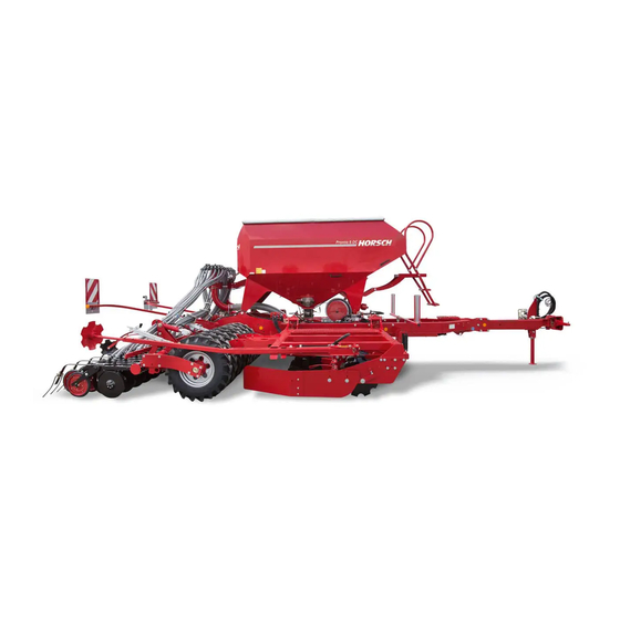
HORSCH Pronto
HORSCH Pronto
7 / 8 / 9 DC 8 PPF
7 / 8 / 9 DC 8 PPF
«
»
396336,
.,
- , .
,
.
7.
(
4 «
» 519
–
texagropark.ru
Operating Instructions
Read carefully prior to starting up!
Keep operating instructions in a safe place!
Art.: 80200202 en
Advertisement
Table of Contents


Need help?
Do you have a question about the Pronto 7 DC and is the answer not in the manual?
Questions and answers