
Subscribe to Our Youtube Channel
Related Manuals for Taylor 60


Summary of Contents for Taylor 60
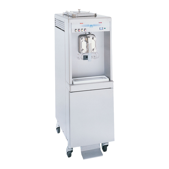
- Page 1 OPERATOR’S MANUAL Model 60 and 62 Shake Freezers Original Operating Instructions 4/00 (Original Publication) 051059-M (Updated 3/27/2020)
- Page 2 Note: Only instructions originating from the factory or its authorized translation representative(s) are considered to be the original set of instructions. © March 2000 Taylor Company (Original Publication) (Updated 3/27/2020) 051059-M Any unauthorized reproduction, disclosure, or distribution of copies by any person of any portion of this work may be...
-
Page 3: Table Of Contents
Auto Lift Switch (Model 60 Only)........ - Page 4 Table of Contents Section 6: Operating Procedures Assembly ............6-1 Sanitizing .
-
Page 5: Section 1: To The Installer
WARNING! This machine must NOT be • Taylor service technicians must ensure that the installed in an area where a water jet or hose can be proper personal protective equipment (PPE) is used. NEVER use a water jet or hose to rinse or clean available and worn when required during the machine. -
Page 6: Air-Cooled Machines
Please contact your local authorities. abrasion. If the supply cord is damaged, it must be FOLLOW YOUR LOCAL ELECTRICAL CODES. replaced by a Taylor service technician to avoid a hazard. To the Installer Models 60 and 62... -
Page 7: Refrigerant
For information regarding applicable local laws, It is recommended that beater rotation adjustment be please contact your local authorized Taylor distributor. performed by a Taylor service technician. Refrigerant IMPORTANT! Refrigerants and their... - Page 8 TO THE INSTALLER Notes: To the Installer Models 60 and 62...
-
Page 9: Section 2: To The Operator
If you require technical assistance, please contact your known to any technician they employ. local Taylor distributor. It should also be noted that Taylor does not warrant the Note: Your Taylor warranty is valid only if the parts are refrigerant used in its machines. For example, if the... - Page 10 TO THE OPERATOR Notes: To the Operator Models 60 and 62...
-
Page 11: Section 3: Safety
Safety Section 3 We at Taylor Company are concerned about the safety of the operator when he or she comes in contact with the freezer and its parts. Taylor has gone to extreme efforts WARNING! Avoid injury. to design and manufacture built-in safety features to •... - Page 12 CAUTION! This machine must be placed on a level surface. Use caution when moving the machine. Failure to comply may cause the machine to tip over and result in personal injury. Safety Models 60 and 62...
-
Page 13: Model 60 Exploded View
Operator Parts Identification Section 4 Model 60 Exploded View Figure 4-1 Item Description Part No. Item Description Part No. Cover A.- Hopper- Std. X38458- SER Caster- 4” Swv 5/8 Stem w/Brake 034081 Knob-Mix Cover 025429 Tank- SYR- 4 Qt 045533... -
Page 14: Model 62 Exploded View
020157 Tube- Feed- 1/4 Hole 015176-5 Shield-Splash 022765 Panel-Rear 039021 Pan-Drip 19-1/2 Long 035034 Panel-Side-Right 085411 Stud-Nose Cone 5/16-18 x 3/8-1 011390 Skirt-Air Flow 049069 Panel A.-Side Left X85409 Leg-4” SS w/O-ring 013458 Operator Parts Identification Models 60 and 62... -
Page 15: Door And Beater Assembly
Blade-Scraper-Plastic 9-13/16L 084950 Tube-Vinyl 3/16ID x 1/16 Wall 020940-6 (Model 60) Shaft-Beater 035527 Items 19, 20, 21, and 17 used on Model 60 only Seal- Drive Shaft 032560 *Bulk Part Number is R30314 **Not Shown Door A.-Partial-1 SPT X17373-SER Operator Parts Identification... -
Page 16: Accessories
021081-2 Plug-Q.D. CO2 1/8 MP 021077 Insert 021081-1 Socket-Q.D. CO2 90 1/4 Barb 021524 Decal-Set 4 Syrup Flavor 021523 Socket-Q.D. Liq.- 90 1/4 Barb 021026 Decal-Syrup Tank Instruction 045533-1 *Not used on chocalate Operator Parts Identification Models 60 and 62... - Page 17 User Interface Section 5 Figure 5-1 Item Description Item Description Spinner Rinse Switch Auto Lift Switch Control Switch Flavor Selector Switches Consistency Control (Switch- Torque) Indicator Lights Dial Light User Interface Models 60 and 62...
-
Page 18: Symbol Definitions
When indicate their functions. Your Taylor machine is designed the light flashes, it indicates that the mix hopper has a with these international symbols. -
Page 19: Consistency Control
Model consistency control knob is below the control switch. To 60. Press the foot pedal. Just before the desired level in achieve a thicker shake, turn the knob clockwise. For a the cup is reached, release the foot pedal. - Page 20 USER INTERFACE Notes: User Interface Models 60 and 62...
-
Page 21: Section 6: Operating Procedures
Operating Procedures Section 6 The Models 60 and 62 have one 7 quart (6.6 liter) 1. Installing the driveshaft: Lubricate the groove and freezing cylinder. These totally automatic freezers offer shaft portion of the beater driveshaft that comes in four separate flavors. Each flavor is blended and ejected contact with the bearing on the beater driveshaft. - Page 22 Make sure the beater assembly is in position over the driveshaft. Turn the beater slightly to make sure it is properly seated. When in position, the beater will not Figure 6-8 protrude beyond the front of the freezing cylinder. Operating Procedures Models 60 and 62...
- Page 23 10. Place the large rubber gasket into the groove on the back side of the freezer door. Do not lubricate the Figure 6-9 gasket. Slide the two O-rings onto the draw valve and lubricate. Figure 6-12 Figure 6-10 Operating Procedures Models 60 and 62...
- Page 24 Do not overtighten. Figure 6-16 Lubricate the spinner blade shaft and insert the spinner blade from the bottom into the center of the draw valve. Figure 6-14 Figure 6-17 Operating Procedures Models 60 and 62...
- Page 25 15. Install the torque arm. Position the torque arm by slipping it up through the slot in the operating arm. Then align the other end down in the hole in the torque rotor shaft, which protrudes from the door. Figure 6-22 Operating Procedures Models 60 and 62...
-
Page 26: Sanitizing
Make sure your hands are clean and sanitized before continuing these instructions. 2. Lay the feed tube in the bottom of the mix hopper. Figure 6-26 Brush-clean the mix inlet hole and the feed tube. Figure 6-24 Figure 6-27 Operating Procedures Models 60 and 62... -
Page 27: Priming
During AUTO operation, make sure the end of cylinder. the feed tube with the hole in it is submerged in the mix. Figure 6-29 7. Stand the feed tube in the corner of the mix hopper. Figure 6-31 Operating Procedures Models 60 and 62... -
Page 28: Syrup System
5. Fill the mix hopper with mix. As the mix level comes in contact with the mix sensing probe on the rear wall of the hopper, the MIX LOW light will stop flashing. Figure 6-36 Figure 6-34 Operating Procedures Models 60 and 62... - Page 29 Figure 6-38 Remove the syrup tank lid by lifting up on the locking lever. Fill the syrup to the indicating mark on the label. Important! Do not overfill the tanks. Figure 6-40 Operating Procedures Models 60 and 62...
- Page 30 Inside the syrup compartment is an air pressure manifold with individual regulators to control the amount of pressure to each tank and syrup line. The left regulator is used for syrup line number 1 and so 6-10 Operating Procedures Models 60 and 62...
-
Page 31: Drawing Product
Recheck the syrup calibration. Tighten the locknut 2. Model 60: To draw product, push the auto lift toggle after the correct calibration is achieved. switch or press the foot pedal. This will cause the: If more than 1 oz. (29.6 ml) of syrup is received, the a. -
Page 32: Closing Procedures
WASH position. 3. Remove the spinner blade by lifting the slip collar on 3. Model 60: With an empty pail under the spinner the spinner coupling. Pull the spinner blade out from housing, push the auto lift toggle switch or press the the bottom of the spinner housing. -
Page 33: Cleaning
Make sure the far right button (VAN) on the selector switch assembly is pressed. Brush-Cleaning 6. Model 60: Press the auto lift toggle switch or press 1. Prepare a sink with an approved 100 ppm cleaning the foot pedal and drain off all the solution. When the ®... -
Page 34: Sanitizing Syrup System
Raise the draw arm and rest the arm on the Prepare 1/2 gal. (1.9 L) of the recommended top of the draw valve. sanitizing solution with warm water in the syrup tank. Brush-clean the inside and outside of the tank. 6-14 Operating Procedures Models 60 and 62... - Page 35 12. Attach the syrup lines to the spinner housing. syrup line until the solution runs clear. Press the far 13. Remove the freezer door and the draw valve. right button (VAN) to stop the flow of sanitizing solution. 6-15 Operating Procedures Models 60 and 62...
- Page 36 OPERATING PROCEDURES Notes: 6-16 Operating Procedures Models 60 and 62...
-
Page 37: Section 7: Operator's Checklist
Dispose of O-rings and seals if they are worn, fresh mix in a ratio of 50:50 during the day’s torn, or fit too loosely, and replace with new ones. operation. Operator’s Checklist Models 60 and 62... -
Page 38: Winter Storage
Kinks can occur when the severe damage to the refrigeration system. machine is moved back and forth for cleaning or Your local Taylor distributor can perform this service for maintenance. Deteriorated or cracked water lines you. -
Page 39: Section 8: Troubleshooting Guide
Calibrate the syrup system. Syrup with product. delivery should be 1 oz. (29.6 ml) in 6 seconds. f. Bad scraper blades. f. Replace scraper blades. g. Dirty condenser (air-cooled) g. Brush condenser clean every 30 days. Troubleshooting Guide Models 60 and 62... - Page 40 Assembly on page 6-1. c. Bad rear shell bearing. c. Call service technician to replace rear - - - shell bearing. d. Driveshaft and beater working d. Call service technician. - - - forward. Troubleshooting Guide Models 60 and 62...
- Page 41 Replace every 3 months. product from spinner missing. housing. b. Wrong O-rings on draw valve. b. Check O-ring size. - - - c. Inadequate lubrication of spinner c. Follow lubrication procedures in shaft. Assembly. Troubleshooting Guide Models 60 and 62...
- Page 42 TROUBLESHOOTING GUIDE Notes: Troubleshooting Guide Models 60 and 62...
- Page 43 Tune−up kits are available from your Taylor distributor. Keep your freezer in top condition with the above replacement parts in a Tune−up kit for your model of freezer. Ask your Taylor distributor about the Automatic 3-Month Tune-Up Kit Mailing Program.
- Page 44 PARTS REPLACEMENT SCHEDULE Notes: Parts Replacement Schedule Models 60 and 62...
- Page 45 LIMITED WARRANTY Taylor warrants the Product against failure due to defect in materials or workmanship under normal use and service as follows. All warranty periods begin on the date of original Product installation. If a part fails due to defect during the applicable warranty period, Taylor, through an authorized Taylor distributor or service agency, will provide a new or ...
- Page 46 LEGAL REMEDIES The owner must notify Taylor in writing, by certified or registered letter to the following address, of any defect or complaint with the Product, stating the defect or complaint and a specific request for repair, replacement, or other correction of the Product under warranty, mailed at least thirty (30) days before pursuing any legal rights or remedies.
- Page 47 Taylor warrants the Parts against failure due to defect in materials or workmanship under normal use and service as follows. All warranty periods begin on the date of original installation of the Part in the Taylor machine. If a Part fails due to defect during the applicable warranty period, Taylor, through an authorized Taylor distributor or service agency, will provide a new or remanufactured Part, at Taylor’s option, to replace the failed defective Part at no charge for the Part.
- Page 48 Parts or the machines in which they are installed repaired or altered in any way so as, in the judgment of Taylor, to adversely affect performance, or normal wear or deterioration.
- Page 49 LEGAL REMEDIES The owner must notify Taylor in writing, by certified or registered letter to the following address, of any defect or complaint with the Part, stating the defect or complaint and a specific request for repair, replacement, or other correction of the Part under warranty, mailed at least thirty (30) days before pursuing any legal rights or remedies.
- Page 50 LIMITED WARRANTY ON PARTS Notes: 11-4 Limited Warranty on Parts Models 60 and 62...
Need help?
Do you have a question about the 60 and is the answer not in the manual?
Questions and answers