Taylor 340 Operator's Manual
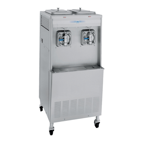
Slush freezers
Hide thumbs
Also See for 340:
- Service instructions manual (76 pages) ,
- Operating instructions manual (43 pages) ,
- Operator's manual (50 pages)

Subscribe to Our Youtube Channel
Related Manuals for Taylor 340


Summary of Contents for Taylor 340
- Page 1 OPERATOR’S MANUAL Model 340, 341, 342 Slush Freezers Original Operating Instructions 028764- M 1/97 (Original Publication) (Updated 6/29/15)
- Page 2 Complete this page for quick reference when service is required: Taylor Distributor: Address: Phone: Service: Parts: Date of Installation: Information found on the data label: Model Number: Serial Number: Electrical Specs: Voltage Cycle Phase Maximum Fuse Size: Minimum Wire Ampacity: E 1997 Carrier Commercial Refrigeration, Inc.
-
Page 3: Table Of Contents
............Models 340, 341, 342 Beater Door Assembly (Standard Door/No Prime Plug) Model 342 Beater Door Assembly With Self- Closing/Prime Plug Door . - Page 4 Statutory Damages of up to $250,000 (17 USC 504) for infringement, and may result in further civil and criminal penalties. All rights reserved. Taylor Company a division of Carrier Commercial Refrigeration, Inc. 750 N. Blackhawk Blvd. Rockton, IL 61072 Table of Contents Models 340, 341, 342...
-
Page 5: To The Installer
For Indoor Use Only: This unit is designed to operate service of Taylor equipment. indoors, under normal ambient temperatures of 70_-75_F (21_-24_C). The freezer has successfully Only authorized Taylor service personnel performed high ambient temperatures should perform installation and repairs on the 104_(40_C) at reduced capacities. -
Page 6: Water Connections (Water Cooled Units Only)
Air Cooled Units CAUTION: THIS EQUIPMENT MUST BE PROPERLY GROUNDED! FAILURE TO DO SO The model 340 air cooled unit requires a minimum of CAN RESULT IN SEVERE PERSONAL INJURY 6” (152 mm) of clearance around both sides of the FROM ELECTRICAL SHOCK! freezer. -
Page 7: Beater Rotation
If burns are severe, apply ice packs and contact a physician immediately. Beater rotation must be clockwise as viewed looking into the freezing cylinder. Taylor reminds technicians to be cautious of Note: The following procedures must... -
Page 8: To The Operator
The unauthorized use of Note: Your Taylor warranty is valid only if the parts are alternate refrigerants will void your Taylor compressor authorized Taylor parts, purchased from the local warranty. -
Page 9: Safety
We, at Taylor Company, are concerned about the safety of the operator when he or she comes in contact with the freezer and its parts. Taylor has gone to extreme efforts to design and manufacture built-in DO NOT operate the freezer unless it is safety features to protect both you and the service properly grounded. - Page 10 Models 341/342: 3” (76 mm) minimum air space on all moving parts. sides. Model 340: 6” (152 mm) minimum air space on sides and 0” at the rear. It is recommended to install a skirt This unit has many sharp edges that can to one side of the unit, and to place the back of the unit cause severe injuries.
-
Page 11: Operator Parts Identification
SHIELD- SPLASH 18” 022763 LOUVER- SIDE- TOP 051192 PANEL A.- FRONT X46881 PANEL- SIDE- RIGHT 047007 PANEL- SIDE- LEFT 047006 LEG- 4.250” 013458 PANEL- SIDE- UPPER 042317 NOTE: STANDARD DOOR SHOWN (NO PRIME PLUG) 150126 Models 340, 341, 342 Operator Parts Identification... -
Page 12: Model 341
SCREW- 10- 24X1/2 TORX 002077 SCREW- 1/4- 20X3/8 SLTD 011694 NUT- 10- 32 FLANGE LOCK 020983 ANGLE- PANEL- R 013828 SCREW- 10- 32X1/2 SERR. 020982 NOTE: STANDARD DOOR SHOWN (NO PRIME PLUG) 150126 Operator Parts Identification Models 340, 341, 342... -
Page 13: Model 342
CASTER- 4” SWV 5/8 STEM 018794 PAN- DRIP 11- 5/8 LONG 027503 SCREW- 1/4- 20X3/8 SLTD 011694 PANEL- SIDE *L 069036 ANGLE- PANEL- R 013828 NOTE: STANDARD DOOR SHOWN (NO PRIME PLUG) 150126 Models 340, 341, 342 Operator Parts Identification... -
Page 14: Models 340, 341, 342 Beater Door Assembly (Standard Door/No Prime Plug)
Models 340, 341, 342 Beater Door Assembly (Standard Door/No Prime Plug) ITEM DESCRIPTION PART NO. ITEM DESCRIPTION PART NO. DOOR A.- SLUSH- PARTIAL X83427SER3 BEARING- FRONT 013116 HANDLE A.- DRAW- SLUSH X47384 BEATER A.- 7 QT- 1 PIN X46233 VALVE- DRAW 047734 CLIP- SCRAPER BLADE*8.75... -
Page 15: Model 342 Beater Door Assembly With Self- Closing/Prime Plug Door
Model 342 Beater Door Assembly With Self- Closing/Prime Plug Door 150427 Models 340, 341, 342 Operator Parts Identification... - Page 16 O- RING- .563 OD X .070W 043758 SHAFT- BEATER 035418 PLUG- PRIME- STNLS 050405 SEAL- DRIVE SHAFT 032560 HANDLE A.- DRAW- SLUSH X47384 O- RING- 7/8 OD X .139W 025307 NUT- STUD 029880 141118 Operator Parts Identification Models 340, 341, 342...
- Page 17 ITEM DESCRIPTION PART NO. KIT A.- TUNE UP X39969- 1 LUBRICANT- TAYLOR 4 OZ. 047518 (STD 340, 341, 342 UNITS) BRUSH- DRAW VALVE 1”OD X 013073 KIT A.- TUNE UP- TORQUE X50413 2”X17” (342 PRIME PLUG, SELF- SANITIZER- STERA SHEEN-...
-
Page 18: Important: To The Operator
To better communicate in the International arena, the words on many of our operator switches and buttons The Models 340 and 341 come equipped with an have symbols to indicate their functions. Your Taylor optional rack assembly and four syrup jars. Each syrup equipment is designed with these International jar holds 16 ounces (453.6 grams) of syrup. -
Page 19: Operating Procedures
“OFF” POSITION. Failure to do so may cause injury from electrocution or hazardous moving parts . Note: When lubricating parts, use an approved food grade lubricant (example: Taylor Lube). Step 1 Slide the o-ring into the first groove on the drive shaft. - Page 20 Note: The hole on the scraper blade must fit securely shaft. Rotate it several times to check for proper over the pin to prevent costly damage. positioning. 150629 Operating Procedures Models 340, 341, 342...
- Page 21 Insert the ice buster through the door spout and into and lubricate. the slot located just above the lower o-ring. Figure 9 Figure 12 150629 Models 340, 341, 342 Operating Procedures...
- Page 22 Note: If the freezer door does not fit into place easily, position the open end of the beater assembly in the 11 o’clock position. Figure 14 Figure 16 150126 Operating Procedures Models 340, 341, 342...
- Page 23 Install the restrictor cap (if applicable). Figure 19 Step B - Self- Closing Door Assembly Turn the door upside down. Insert the spring. Figure 18 Proceed to Step 19 on page 23. Figure 20 150126 Models 340, 341, 342 Operating Procedures...
- Page 24 Insert the draw valve above the lower o-ring. handle through the slot and into the draw valve hole. Figure 22 Figure 24 141119 Operating Procedures Models 340, 341, 342...
- Page 25 Install it on the other side, through the longer Step J - Self- Closing Door Assembly slot and into the draw valve hole. Place the o-ring onto the prime plug and lubricate. Figure 26 Figure 28 141119 Models 340, 341, 342 Operating Procedures...
- Page 26 Note: If the freezer door does not fit into place easily, position the open end of the beater assembly in the 11 o'clock position. Figure 30 Figure 32 141119 Operating Procedures Models 340, 341, 342...
- Page 27 Lay the hopper gasket and feed tube in the bottom of Slide the long drip pan into the hole in the front the mix hopper. panel. Figure 34 Proceed to Step 19. Figure 36 141119 Models 340, 341, 342 Operating Procedures...
-
Page 28: Sanitizing
Allow the solution to agitate for five minutes. MANUFACTURER’S SPECIFICATIONS. Step 2 Pour the sanitizing solution into the hopper and allow it to flow into the freezing cylinder. Figure 38 Figure 40 120619 Operating Procedures Models 340, 341, 342... -
Page 29: Priming
Step 3 tube in the corner of the hopper. Place the control switch in the “AUTO” position. When the unit cycles off, the product will be at serving viscosity. Figure 42 Figure 44 150629 Models 340, 341, 342 Operating Procedures... -
Page 30: Closing Procedure
Step 5 Figure 47 Place the hopper cover into position. Closing Procedure To disassemble the Models 340, 341, and 342, the following items will be needed: Two cleaning pails Sanitized stainless steel rerun can with lid Necessary brushes (provided with the... -
Page 31: Draining Product From The Freezing Cylinder
“OFF” position. Repeat this procedure until the rinse water being Figure 49 drawn from the freezing cylinder is clear. 140721 Models 340, 341, 342 Operating Procedures... -
Page 32: Cleaning
Step 3 control switch in the “OFF” position. While the solution is flowing into the freezing cylinder, brush clean the mix hopper and the mix inlet hole. Figure 52 Figure 54 150126 Operating Procedures Models 340, 341, 342... -
Page 33: Disassembly
With the other hand, push the top of the o-ring forward and it will roll Step 7 out of the groove and can be easily removed. Wipe clean all exterior surfaces of the freezer. 141120 Models 340, 341, 342 Operating Procedures... -
Page 34: Important: Operator Checklist
NSF approved maintenance purposes. Deteriorated cracked water lines should be replaced only by stainless steel rerun container and used the following day. DO NOT prime the machine with an authorized Taylor mechanic. 110620 Important: Operator Checklist Models 340, 341, 342... -
Page 35: Winter Storage
Winter Storage If the place of business is to be closed during the winter Your local Taylor Distributor can perform this service months, it is important to protect the freezer by for you. following certain precautions, particularly if the Wrap detachable parts of the freezer such as beater, building is subject to freezing conditions. -
Page 36: Troubleshooting Guide
Adjust accordingly. knob needs adjusting. d. Improper mixing of d. Carefully follow the directions for mixing product. product. e. There is insufficient e. Keep the hopper full of mix. product in the freezing cylinder. Troubleshooting Guide Models 340, 341, 342... - Page 37 Contact service technician if the problem continues. c. The circuit breaker is c. Reset the circuit breaker or replace the blown fuse. tripped or the fuse is blown. 150622 Models 340, 341, 342 Troubleshooting Guide...
- Page 38 11. The door will not go into a. The beater assembly is a. The open end of the beater assembly should position easily. incorrectly positioned. be in the 11 o’clock position. Troubleshooting Guide Models 340, 341, 342...
-
Page 39: Parts Replacement Schedule
Minimum if Necessary White Bristle Brush, 1” x 2” Inspect & Replace Minimum if Necessary White Bristle Brush, 3” x 7” Inspect & Replace Minimum if Necessary *Double quantity for the Model 342. Models 340, 341, 342 Parts Replacement Schedule... -
Page 40: Section 10 Limited Warranty On Equipment
Taylor, through an authorized Taylor distributor or service agency, will provide a new or re- manufactured part, at Taylor’s option, to replace the failed defective part at no charge for the part. Except as otherwise stated herein, these are Taylor’s exclusive obligations under this limited warranty for a Product failure. - Page 41 LEGAL REMEDIES The owner must notify Taylor in writing, by certified or registered letter to the following address, of any defect or complaint with the Product, stating the defect or complaint and a specific request for repair, replacement, or other correction of the Product under warranty, mailed at least thirty (30) days before pursuing any legal rights or remedies.
-
Page 42: Limited Warranty On Parts
Taylor warrants the Parts against failure due to defect in materials or workmanship under normal use and service as follows. All warranty periods begin on the date of original installation of the Part in the Taylor unit. If a Part fails due to defect during the applicable warranty period, Taylor, through an authorized Taylor distributor or service agency, will provide a new or re- manufactured Part, at Taylor’s option, to replace the failed defective Part at no... - Page 43 Parts or the units in which they are installed repaired or altered in any way so as, in the judgment of Taylor, to adversely affect performance, or normal wear or deterioration.
-
Page 44: Taylor Company
LEGAL REMEDIES The owner must notify Taylor in writing, by certified or registered letter to the following address, of any defect or complaint with the Part, stating the defect or complaint and a specific request for repair, replacement, or other correction of the Part under warranty, mailed at least thirty (30) days before pursuing any legal rights or remedies.
Need help?
Do you have a question about the 340 and is the answer not in the manual?
Questions and answers