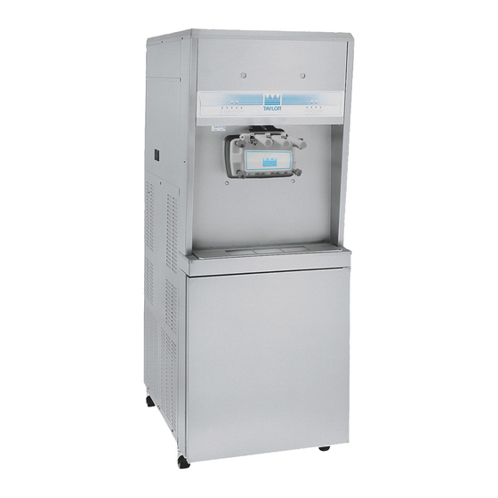
Taylor 8756 Operator's Manual
Single-stage pump soft serve freezer
Hide thumbs
Also See for 8756:
- Operator's manual (50 pages) ,
- Operating instructions manual (70 pages) ,
- Original operating instructions (58 pages)

Related Manuals for Taylor 8756


Summary of Contents for Taylor 8756
- Page 1 OPERATOR’S MANUAL Model 8756 Single-Stage Pump Soft Serve Freezer Original Operating Instructions 11/15/10 (Original Publication) 069071-M (Updated 8/13/2020)
- Page 2 Note: Only instructions originating from the factory or its authorized translation representative(s) are considered to be the original set of instructions. © November 2010, Taylor Company. (Updated 8/13/2020) 069071-M Any unauthorized reproduction, disclosure, or distribution of copies by any person of any portion of this work may be...
-
Page 3: Table Of Contents
Table of Contents Section 1: To the Installer Installer Safety ............1-1 Site Preparation . - Page 4 Table of Contents Section 7: Operator Checklist During Cleaning and Sanitizing ......... . 7-1 Troubleshooting Bacterial Count .
-
Page 5: Section 1: To The Installer
Taylor distributor. Note: All repairs must be performed by a Taylor service technician. This machine is made using USA sizes of hardware. All metric conversions are approximate and vary in size. -
Page 6: Air-Cooled Machines
WARNING! Avoid injury. • DO NOT operate the machine unless it is properly grounded. • DO NOT operate the machine with fuses larger than specified on the machine's data label. To the Installer Model 8756... -
Page 7: Beater Rotation
It is recommended that beater rotation adjustment be GFI, installed by the authorized personnel to performed by an authorized Taylor service technician. local codes. Refrigerant •... - Page 8 For information regarding applicable local laws, please contact your local authorized Taylor distributor. IMPORTANT! Refrigerants and their associated lubricants may be extremely moisture absorbent. When opening a refrigeration system, the maximum time the system is open must not exceed 15 minutes.
-
Page 9: Section 2: To The Operator
If you require technical assistance, please contact your local authorized Taylor distributor. Note: Your Taylor warranty is valid only if the parts are authorized Taylor parts, purchased from the local authorized Taylor distributor, and only if all required service work is provided by an authorized Taylor service technician. - Page 10 It should also be noted that Taylor does not warrant the refrigerant used in its machine. For example, if the refrigerant is lost during the course of ordinary service to...
-
Page 11: Section 3: Safety
Safety Section 3 We at Taylor Company are concerned about the safety of operators at all times when they are coming in contact with the machine and its parts. Taylor makes every effort WARNING! Avoid injury. to design and manufacture built-in safety features to •... - Page 12 Failure to follow these instructions may result in trained personnel. Failure to comply may result in electrocution. Contact your local authorized Taylor personal injury. distributor for service. WARNING! This machine must NOT be...
-
Page 13: Section 4: Operator Parts Identification
Operator Parts Identification Section 4 Model 8756 Figure 4-1 Operator Parts Identification Model 8756... - Page 14 OPERATOR PARTS IDENTIFICATION 8756 Parts Identification Item Description Part No. Item Description Part No. Panel A.-Front X22879 Cover-Mix Tank 024590 Stud-Nose Cone 068410 Funnel-Mix 036637 Bolt-Carriage 012347 Tray-Drip 22-7/8 X 5-1/8 014533 Panel A.-Lower Side (R & L) X23956 Shield-Splash 23” Long...
-
Page 15: Beater Door Assembly
X51532-12 Plug-Prime 028805 O-ring-7/8 OD X .103W 014402 Gasket-Door HT 4"-Double 048926 Cap-Design-1.010" ID-6 Point 014218 Kit A.-Beater-Front Shoes X50350 Valve A.-Draw X18303 Shoe-Front Helix-Rear 050346 Nut-Stud-Short 034383 Bearing-Front-Shoe 050348 Nut-Stud-Long 034382 Shoe-Front Helix-Front 050347 Operator Parts Identification Model 8756... -
Page 16: Air/Mix Pump Assembly
Orifice 023425-50 O-ring - 3/8 OD x .070 W 016137 Line A.-Flare 038299 Line A.-Pump Pressure X27139 Diaphragm-Pressure 020249 Switch Tube-Vinyl 5/8 ID X 1/8 Wall 020945-18 Counterweight-Suction Tube 020452 *Includes Items 3a-3h Figure 4-3 Operator Parts Identification Model 8756... -
Page 17: Accessories
OPERATOR PARTS IDENTIFICATION Accessories Apply the appropriate Taylor approved food safe lubricant. Figure 4-4 Item Description Part No. Item Description Part No. Brush-Mix Pump Body 023316 Brush-Draw Valve 013073 Brush-Pressure Switch 027647 Sanitizer See Note Brush Set-LVB 050103 Lubricant-Taylor 4 oz. - Page 18 OPERATOR PARTS IDENTIFICATION Notes: Operator Parts Identification Model 8756...
- Page 19 User Interface Section 5 Figure 5-1 Item Description Item Description Power Switch (Toggle) AUTO Key RESET Button PUMP Key MIX Refrigeration Control MIX LOW Indicator STANDBY Key MIX OUT Indicator WASH Key User Interface Model 8756...
-
Page 20: Symbol Definitions
Softech controls. The reset protects the beater motor have symbols to indicate their functions. Your Taylor from an overload condition. If an overload occurs, the machine is designed with these international symbols. -
Page 21: Wash
Note: An indicating light and an audible tone will sound whenever a mode of operation has been pressed. To cancel any function, press the key again and the light and mode of operation will shut off. User Interface Model 8756... - Page 22 USER INTERFACE Notes: User Interface Model 8756...
-
Page 23: Section 6: Operating Procedures
Operating Procedures Section 6 The Model 8756 has two freezing cylinders. The size of 11033 each freezing cylinder is 3.4 qt (3.2 L). Mix is stored in the lower front refrigerated compartment and is pumped up to the freezing cylinder by an air/mix pump. - Page 24 5. If the blades are in good condition, place the rear scraper blade over the rear holding pin on the beater. Important! The hole on the scraper blade must fit securely over the pin to prevent costly damage. Operating Procedures Model 8756...
- Page 25 1. Before assembling the freezer door, check the following for any nicks, cracks, or signs of wear: door Apply the appropriate Taylor approved food safe lubricant. bearings, door gaskets, draw valves, O-rings, and all sides of the door assembly, including the inside of the draw valve bores.
- Page 26 Figure 6-13 11432 Draw Valve 1. Slide the two O-rings into the grooves on the draw valves and lubricate each O-ring. 11428 Apply the appropriate Taylor approved food safe lubricant. Figure 6-12 Figure 6-14 Operating Procedures Model 8756...
- Page 27 Secure the left draw handle with the short pivot pin. 11429 11436 Apply the appropriate Taylor approved food safe lubricant. Figure 6-17 Figure 6-15 Note: This machine features adjustable draw handles 3. Lubricate and install the O-rings into the grooves on to provide the best portion control, giving a better the pivot pins.
-
Page 28: Air/Mix Pump Assembly
6. Insert the rear drip pan into the opening on the side 15045 panel. 10176i Apply the appropriate Taylor approved food safe lubricant. Figure 6-21 Note: A concave check band indicates an incorrect Figure 6-19 assembly. Turn the check band inside out to correctly 7. - Page 29 Do not lubricate the check bands or O-rings. bottom. 15017 15044 Apply the appropriate Taylor approved food safe lubricant. Apply the appropriate Taylor approved food safe lubricant. Figure 6-25 Figure 6-28 6. Insert the piston, air orifice end first, into the pump 8.
- Page 30 Attach one end of the flare line to the threaded fitting on the lower side of the pump body. Allow the other end to hang freely. Apply the appropriate Taylor approved food safe lubricant. 15097 Figure 6-30 10. Insert the mix inlet fitting into the hole in the base of the liquid valve body.
-
Page 31: Sanitizing
15056 Figure 6-38 Note: Repeat these steps for other the side of freezer. Apply the appropriate Taylor approved food safe lubricant. Sanitizing 1. Prepare a pail of approved 100 ppm sanitizing ® or solution (examples: 2-1/2 gal. [9.5 L] of Kay-5 ®... - Page 32 13038p Figure 6-40 5. Attach the quick disconnect fitting of the pressure line to the other fitting on the mix inlet tube. Allow the other end to hang free. 15061 Figure 6-43 Figure 6-41 6-10 Operating Procedures Model 8756...
- Page 33 Momentarily open the center draw handle to sanitize the center door spout. 13038p Figure 6-45 11. Press the WASH and PUMP keys. The indicator lights will illuminate, indicating pump and beater motor operation. 13038p Figure 6-48 Figure 6-46 6-11 Operating Procedures Model 8756...
-
Page 34: Priming
1. Place the mix tank and the cover in the mix cabinet. Close the mix cabinet door. 2. Insert the prongs of the mix probe inside the mix tank. Connect the mix probe in the socket receptacle. 15064 Figure 6-50 6-12 Operating Procedures Model 8756... - Page 35 Leaving the door open while the mix refrigeration system is active may cause the evaporator to ice up and impair the mix cabinet refrigeration. 6-13 Operating Procedures Model 8756...
-
Page 36: Closing Procedure
3. Press the PUMP key. This action will cause the rinse water to be pumped through the air/mix pump and out through the pressure line. After approximately 15 seconds, press the PUMP key to stop operation. 6-14 Operating Procedures Model 8756... -
Page 37: Cleaning
Figure 6-60 3. Disconnect the pressure line from the pressure switch and place it in the pail of cleaning solution. 6-15 Operating Procedures Model 8756... -
Page 38: Disassembly
1. Remove the handscrews, freezer door, beaters, shoes, scraper blades, and driveshafts from the freezing cylinders. Take these parts to the sink for cleaning. 6-16 Operating Procedures Model 8756... - Page 39 9. Place the parts on a clean, dry surface to air-dry overnight. 10. Wipe clean all exterior surfaces of the freezer and the mix cabinet. Figure 6-65 Important! Cleaning the tubes requires special attention because bacteria and milkstone can build up here. 6-17 Operating Procedures Model 8756...
- Page 40 OPERATING PROCEDURES Notes: 6-18 Operating Procedures Model 8756...
-
Page 41: Section 7: Operator Checklist
Sanitize the freezing cylinder for 5 minutes. The temperature of the mix in the mix cabinet and the walk-in cooler should be below 38°F (3.3°C). Operator Checklist Model 8756... -
Page 42: Air/Mix Pump
Clean, sanitize, and lubricate the pressure switch diaphragm daily. Make sure the air/mix pump is properly aligned with the face plate of the motor reducer or severe and costly damage may occur. Operator Checklist Model 8756... -
Page 43: Section 8: Troubleshooting Guide
The mix inlet tube is frozen or g. Use the long, flexible brush and clogged. sanitizing solution to clear the restriction in the mix inlet tube. Contact a Taylor - - - service technician to correct the cause of over-refrigeration in the mix cabinet. - Page 44 Improper lubrication of the b. Lubricate properly. driveshaft. c. Worn rear shell bearing. c. Contact a Taylor service technician to - - - replace the rear shell bearing. d. The gearbox is out of alignment. d. Contact a Taylor service technician to - - - align the gearbox.
- Page 45 The diaphragm must be correctly was installed incorrectly or is installed in the pressure switch cap. missing. c. Defective air/mix pump pressure c. Contact a Taylor service technician to - - - switch. replace the pressure switch. 12. The machine will not a.
- Page 46 TROUBLESHOOTING GUIDE Notes: Troubleshooting Guide Model 8756...
- Page 47 Inspect and replace if Minimum necessary. White Bristle Brush, 3” x 7” Inspect and replace if Minimum necessary. Small White Bristle Brush, 1/8” Inspect and replace if Minimum necessary. Brush Set Inspect and replace if Minimum necessary. Parts Replacement Schedule Model 8756...
- Page 48 PARTS REPLACEMENT SCHEDULE Notes: Parts Replacement Schedule Model 8756...
- Page 49 LIMITED WARRANTY Taylor warrants the Product against failure due to defect in materials or workmanship under normal use and service as follows. All warranty periods begin on the date of original Product installation. If a part fails due to defect during the applicable warranty period, Taylor, through an authorized Taylor distributor or service agency, will provide a new or ...
- Page 50 7. Failure, damage, or repairs due to faulty installation, misapplication, abuse, no or improper servicing, unauthorized alteration, or improper operation or use as indicated in the Taylor Operator’s Manual, including but not limited to the failure to use proper assembly and cleaning techniques, tools, or approved cleaning supplies.
- Page 51 LEGAL REMEDIES The owner must notify Taylor in writing, by certified or registered letter to the following address, of any defect or complaint with the Product, stating the defect or complaint and a specific request for repair, replacement, or other correction of the Product under warranty, mailed at least thirty (30) days before pursuing any legal rights or remedies.
- Page 52 LIMITED WARRANTY ON EQUIPMENT Notes: 10-4 Limited Warranty on Equipment Model 8756...
- Page 53 Taylor warrants the Parts against failure due to defect in materials or workmanship under normal use and service as follows. All warranty periods begin on the date of original installation of the Part in the Taylor machine. If a Part fails due to defect during the applicable warranty period, Taylor, through an authorized Taylor distributor or service agency, will provide a new or remanufactured Part, at Taylor’s option, to replace the failed defective Part at no charge for the Part.
- Page 54 Parts or the machines in which they are installed repaired or altered in any way so as, in the judgment of Taylor, to adversely affect performance, or normal wear or deterioration.
- Page 55 LEGAL REMEDIES The owner must notify Taylor in writing, by certified or registered letter to the following address, of any defect or complaint with the Part, stating the defect or complaint and a specific request for repair, replacement, or other correction of the Part under warranty, mailed at least thirty (30) days before pursuing any legal rights or remedies.
- Page 56 LIMITED WARRANTY ON PARTS Notes: 11-4 Limited Warranty on Parts Model 8756...
- Page 57 Wiring Diagrams Section 12 Model 8756 037807-33 2015 Taylor Company 4/15 12-1 Wiring Diagrams Model 8756...
- Page 58 WIRING DIAGRAMS Notes: 12-2 Wiring Diagrams Model 8756...
Need help?
Do you have a question about the 8756 and is the answer not in the manual?
Questions and answers
Peça para refrigeração
Qual a quantidade de de fluido refrigerante que colocamos ,no compressor