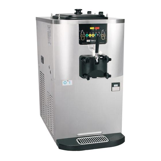
Taylor C706 Operator's Manual
Soft serve freezer
Hide thumbs
Also See for C706:
- Operator's manual (40 pages) ,
- Original operating instructions (47 pages)

Related Manuals for Taylor C706


Summary of Contents for Taylor C706
- Page 1 OPERATOR’S MANUAL Model C706 Soft Serve Freezer Original Operating Instructions February 2003 (Original Publication) 056436-M (Updated 6/10/2019)
- Page 2 Note: Only instructions originating from the factory or its authorized translation representative(s) are considered to be the original set of instructions. © 2003 Taylor Company 056436-M Any unauthorized reproduction, disclosure, or distribution of copies by any person of any portion of this work may be...
-
Page 3: Table Of Contents
Section 4: Operator Parts Identification Model C706 Single Spout Door and Beater Assembly ......4-2 X57029-XX Pump A.—Mix Simplified ........4-3 Accessories. - Page 4 Table of Contents Section 6: Operating Procedures Prior to Setup (Freezers with Topping Pumps Only) ......6-1 Assembly .
-
Page 5: Section 1: To The Installer
Installation Checklist. WARNING! This machine has many sharp edges that can cause severe injuries. Installer Safety All repairs must be performed by an authorized Taylor service technician. Site Preparation Review the area where the machine will be installed before uncrating the machine. -
Page 6: Water Connections
WARNING! DO NOT operate this machine with fuses larger than specified on the machine data label. Failure to follow this instruction may result in electrocution or damage to the machine. To the Installer Model C706... -
Page 7: Beater Rotation
Cap all open tubing to prevent humid air or service panel. water from being absorbed by the oil. It is recommended that beater rotation adjustment be performed by an authorized Taylor service technician. To the Installer Model C706... - Page 8 TO THE INSTALLER Notes: To the Installer Model C706...
-
Page 9: Section 2: To The Operator
If you should require technical assistance, please contact an authorized Taylor distributor. Note: Your Taylor warranty is valid only if the parts are authorized Taylor parts, purchased from the local authorized Taylor distributor, and only if all required service work is provided by an authorized Taylor service technician. - Page 10 TO THE OPERATOR Compressor Warranty Disclaimer It should also be noted that Taylor does not warrant the refrigerant used in its equipment. For example, if the The refrigeration compressor(s) on this machine are refrigerant is lost during the course of ordinary service to...
-
Page 11: Section 3: Safety
(5021 of and its parts. Taylor has gone to extreme efforts to design IEC 60417-1) on both the removable panel and the and manufacture built-in safety features to protect both machine's frame. - Page 12 IMPORTANT! Access to the service area of Failure to follow these instructions may result in the machine is restricted to persons having knowledge electrocution. Contact your local authorized Taylor and practical experience with the machine, in particular distributor for service.
- Page 13 A minimum of 6 in. (152 mm) air space is required on both sides and 0 in. (0 mm) on the rear. Failure to follow this instruction may cause poor freezer performance and damage to the machine. Safety Model C706...
- Page 14 SAFETY Notes: Safety Model C706...
- Page 15 (Optional) Stud-Nose Cone 055987 Guard-Fan 028534-1 Shield-Splash 049203 Orifice 022465-100 Tray-Drip *Black 056858 O-ring-3/8 OD X 0.070W 016137 Panel-Front-Lower 058942 O-ring-.643 OD X 0.077W 018572 Panel A.-Front-Upper X58950 Tube A.-Feed-SS-5/32 Hole X29429-2 *Optional feed tube. Operator Parts Identification Model C706...
-
Page 16: Model C706 Single Spout Door And Beater Assembly
OPERATOR PARTS IDENTIFICATION Model C706 Single Spout Door and Beater Assembly Figure 4-2 Item Description Part No. Item Description Part No. Door A.-w/ Baffle X56071-SER O-ring -7/8 OD X 0.103 W 014402 Handle A.-Draw-Welded X56246 Nut-Stud Black-3.25 Long 058765 Screw-Adjustment-5/16-24 056332 Nut-Stud Black-2.56 Long... -
Page 17: X57029-Xx Pump A.-Mix Simplified
*(25 to Bag)* Cap-Valve Body SS 056874-14 Clip-Retainer-Mix Pump 044641 Gasket-Simplified Pump Valve 086097 Tube A.-Feed-Hopper S.S. X56521 Adaptor-Mix Inlet-SS-Red 054825 Ring-Check-Feed-Tube 056524 O-ring-11/16ODX0.103W-Red 016132 *50 To Bag* Sleeve A.-Mix Pump *HT X44761 Pin-Cotter-Hairpin-1/8DIA 044731 Operator Parts Identification Model C706... -
Page 18: Accessories
Brush-Rear·BRG·1 in. DX2 in. Pail-10 qt. Brush-Double·Ended Brush-End-Door-Spout Brush-Draw·Valve·1 in. ODX2” Brush-Set·LVB Brush-Mix·Pump·Body-3”X7” Brush-Pump·Spout ® *Item 6: A sample of Stera-Sheen is shipped with new equipment. To order additional sanitizer, use the part number listed. Operator Parts Identification Model C706... - Page 19 PUMP Key MIX OUT Indicator Light RESET Button-Beater Motor MIX REF Key Reset Button -Pump STANDBY Key Power Switch (Toggle) WASH Key Hopper Temp. Indicator AUTO Key Optional Flavor Burst Jack *Not available on all machines. User Interface Model C706...
-
Page 20: Symbol Definitions
Your Taylor operating. The MIX REF function cannot be canceled machine is designed with these International symbols. -
Page 21: Auto Key
An indicating light illuminates and an audible tone sounds when a mode of operation has been The Model C706 features an adjustable draw handle to pressed. To cancel any function, press the key again. provide the best portion control. The draw handle should The indicator light and mode of operation will shutoff. -
Page 22: Optional Feed Tube (Backup Option)
O-ring-3/8” OD X 0.070 W the freezing cylinder. The air orifice maintains overrun and allows enough mix to enter the freezing cylinder after X29429-2 Tube A.-Feed-SS 5/32” Hole a draw. 018572 O-ring-0.643 OD X 0.077 W User Interface Model C706... -
Page 23: Section 6: Operating Procedures
Operating Procedures Section 6 The C706 machine stores mix in a hopper. The mix is Assembly pumped from the hopper into the freezing cylinder. The Note: When lubricating parts, use an approved food machine has a 3.4 qt. (3.2 L) capacity freezing cylinder grade lubricant (example: Taylor Lube). - Page 24 Make sure the beater assembly is in position over the driveshaft. Turn the beater slightly to be certain it is properly seated. When in position, the beater should not protrude beyond the front of the freezing cylinder. Operating Procedures Model C706...
- Page 25 11294 Figure 6-6 11. Slide the two O-rings into the grooves on the prime plug. Apply an even coat of Taylor Lube to the O-rings and shaft. 11092 Figure 6-9 14. Insert the draw valve from the top until it reaches the bottom.
-
Page 26: Mix Hopper Assembly
2. Assemble the mix inlet assembly. Slide the O-ring 17. Install the front drip tray and the splash shield under into the groove of the valve body cap. Do not the door spout. lubricate the O-ring. 10504 15109 Figure 6-12 Figure 6-14 Operating Procedures Model C706... - Page 27 Figure 6-16 8. Insert the mix inlet assembly into the pump cylinder. 5. Assemble the piston. Slide the red O-ring into the 15205 groove of the piston. Do not lubricate the O-ring. 15117 Figure 6-20 Figure 6-17 Operating Procedures Model C706...
- Page 28 Note: The head of the retaining pin should be facing up with the pump correctly installed. 10. Assemble the feed tube assembly. Slide the valve O-ring into the groove of the feed tube. 15115 Figure 6-24 Figure 6-22 Operating Procedures Model C706...
-
Page 29: Sanitizing
Figure 6-26 Note: For ease in installing the pump, position the ball crank of the driveshaft in the 3 o’clock position. Operating Procedures Model C706... - Page 30 Figure 6-30 7. With an empty pail beneath the door spout, raise the prime plug and press the PUMP key. Figure 6-28 10505 5. Place the power switch in the ON position. 13063 Figure 6-31 Figure 6-29 Operating Procedures Model C706...
-
Page 31: Priming
Failure to follow this instruction may result in damage to the freezing cylinder. Note: Make sure your hands are clean and sanitized before continuing these instructions. Figure 6-35 Operating Procedures Model C706... -
Page 32: Closing Procedure
MIX LOW indicator light will shutoff. Note: The MIX REF indicator light will come on, showing the mix refrigeration system is maintaining the mix in the hopper. 6. Place the mix hopper cover in position. 6-10 Operating Procedures Model C706... -
Page 33: Rinsing
WASH key, canceling the Wash mode. solution can cause parts damage, while too mild of a solution will not provide adequate cleaning. Make sure all brushes provided with the freezer are available for brush cleaning. Operating Procedures 6-11 Model C706... - Page 34 With the black-bristle brush, brush clean the rear shell bearing at the back of the freezing cylinder Brush clean the drive hub opening in the rear wall of the mix hopper. 10361 Figure 6-38 6-12 Operating Procedures Model C706...
- Page 35 054068 013072 White Bristle - 1/2” x 1/2” White Bristle - 1/2” x 1” 050103 039718 White Bristle - 3/16” x 1” White Bristle - 3” x 1/2” 013072 Black Bristle - 1/4” x 1-1/4” Operating Procedures 6-13 Model C706...
- Page 36 OPERATING PROCEDURES Notes: 6-14 Operating Procedures Model C706...
-
Page 37: Section 7: Operator's Checklist
50/50 WARNING! Always disconnect electrical during the day's operation. power prior to cleaning the condenser. Failure to follow this instruction may result in electrocution. Operator’s Checklist Model C706... -
Page 38: Air/Mix Pump Checklist
Taylor service technician. Your local Taylor service technician can perform this winter storage service for you. Air/Mix Pump Checklist Wrap detachable parts of the freezer, such as the beater, ... -
Page 39: Section 8: Troubleshooting Guide
Probable Cause Remedy Ref. 1. No product is being a. Freeze-up in mix inlet hole. a. Call a Taylor service technician to - - - dispensed with the draw adjust the mix hopper temperature. valve open and the b. Beater motor out on reset. - Page 40 Install or replace regularly. 6-1/9-1 into the rear drip pan. driveshaft. b. The rear shell bearing is worn. b. Call Taylor service technician to - - - replace rear shell bearing. a. Missing or worn draw valve 9. Excessive mix leakage a.
- Page 41 Follow lubrication procedures cylinder wear. of pump cylinder. carefully. b. Incorrect ball crank rotation. b. Contact a Taylor service technician. - - - 16.Pitting occurring inside a. Cleaner was left inside the pump a. After brush cleaning the pump the pump cylinder.
- Page 42 TROUBLESHOOTING GUIDE Notes: Troubleshooting Guide Model C706...
-
Page 43: Section 9: Parts Replacement Schedule
White Bristle Brush, 1/2 in. x 1/2 in. Inspect and replace if necessary. Minimum White Bristle Brush, 3/16 in. x 1 in. Inspect and replace if necessary. Minimum White Bristle Brush, 3 in. x 1/2 in. Inspect and replace if necessary. Minimum Parts Replacement Schedule Model C706... - Page 44 PARTS REPLACEMENT SCHEDULE Notes: Parts Replacement Schedule Model C706...
-
Page 45: Section 10: Limited Warranty On Equipment
LIMITED WARRANTY Taylor warrants the Product against failure due to defect in materials or workmanship under normal use and service as follows. All warranty periods begin on the date of original Product installation. If a part fails due to defect during the applicable warranty period, Taylor, through an authorized Taylor distributor or service agency, will provide a new or ... - Page 46 7. Failure, damage, or repairs due to faulty installation, misapplication, abuse, no or improper servicing, unauthorized alteration or improper operation or use as indicated in the Taylor Operator’s Manual, including but not limited to the failure to use proper assembly and cleaning techniques, tools, or approved cleaning supplies.
- Page 47 LEGAL REMEDIES The owner must notify Taylor in writing, by certified or registered letter to the following address, of any defect or complaint with the Product, stating the defect or complaint and a specific request for repair, replacement, or other correction of the Product under warranty, mailed at least thirty (30) days before pursuing any legal rights or remedies.
- Page 48 LIMITED WARRANTY ON EQUIPMENT Notes: 10-4 Limited Warranty on Equipment Model C706...
-
Page 49: Section 11: Limited Warranty On Parts
Taylor warrants the Parts against failure due to defect in materials or workmanship under normal use and service as follows. All warranty periods begin on the date of original installation of the Part in the Taylor unit. If a Part fails due to defect during the applicable warranty period, Taylor, through an authorized Taylor distributor or service agency, will provide a new or remanufactured Part, at Taylor’s option, to replace the failed defective Part at no charge for the Part. - Page 50 Taylor. 5. Replacement of wear items designated as Class “000” Parts in the Taylor Operator’s Manual, as well as any release sheets and clips for the Product’s upper platen assembly.
- Page 51 LEGAL REMEDIES The owner must notify Taylor in writing, by certified or registered letter to the following address, of any defect or complaint with the Part, stating the defect or complaint and a specific request for repair, replacement, or other correction of the Part under warranty, mailed at least thirty (30) days before pursuing any legal rights or remedies.
- Page 52 LIMITED WARRANTY ON PARTS Notes: 11-4 Limited Warranty on Parts Model C706...
Need help?
Do you have a question about the C706 and is the answer not in the manual?
Questions and answers