
Related Manuals for Taylor 430


Summary of Contents for Taylor 430
- Page 1 SERVICE MANUAL Model 430 Shake/Slush Freezer Original Service Instructions 051430−S 2/98 (Original Publication) (Updated 10/5/15)
-
Page 3: Table Of Contents
............. Model 430 Specifications . - Page 4 ........... . CAUTION: Information in this manual is intended to be used by Taylor Authorized Service Technicians only.
-
Page 5: Section 1: Introduction
Section 1: Introduction Safety Model 430 Specifications Running Specifications General Installation Instructions Environmental Notices Introduction Model 430... -
Page 6: Safety
The many the terminals and protect the insulation of built−in safety features that are part of all Taylor the conductors from abrasion. equipment are aimed at protecting operators and trained service technicians alike. - Page 7 Please refer to the water jet or hose on or around this equipment may cleaning section of the Operator Manual for the proper result in electrocution to the user or damage to the procedure to clean this unit. equipment. 081202 Introduction Model 430...
-
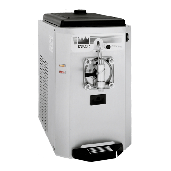
Page 8: Model 430 Specifications
Model 430 Specifications Freezing Cylinder Air Cooled One, 4 quart (3.8 liter) capacity. Clearance: 3” (76.2 mm) around all sides. Mix Hopper Water Cooled One, 14 quart (13.2 liter) capacity. Refrigerated and insulated. The water inlet and drain connections are located in the rear panel (3/8”... - Page 9 Figure 1 Introduction Model 430...
-
Page 10: Running Specifications
E.P.R. valve. The E.P.R. valve is (2,069 - 2,344 kPa.) factory set at 67 - 69 PSI (462 - 476 kPa.) in order to 100_ 37.8_ 340 - 380 maintain hopper product temperature below 40_F. (2,344 - 2,620 kPa.) (4_C.). 150210 Introduction Model 430... -
Page 11: General Installation Instructions
Two or more people are required to safely move this unit. Failure to comply may result in personal injury or Examples: equipment damage. scraper blades Uncrate the machine. Inspect the unit for damage. Report any damage to the Taylor factory immediately. condenser fins 150210 Introduction Model 430... - Page 12 FROM ELECTRICAL SHOCK! looking into the freezing cylinder. The following repairs must be performed by an authorized Taylor Service Technician. Note: This unit is provided with an equipotential grounding lug that is to be properly attached to either the rear of the frame or the under side of the base pan Disconnect all power to the unit.
- Page 13 Refrigerant technicians they employ. In consideration of our environment, Taylor proudly It should be noted, that Taylor does not warrant the uses only earth friendly HFC refrigerants. The HFC refrigerant used in its equipment. For example, if the refrigerant used in this unit is R404A. This refrigerant...
-
Page 14: Environmental Notices
The user is responsible for returning the product to the _________________________________ appropriate collection facility, as specified by your local In consideration of our environment, Taylor proudly code. uses only earth friendly HFC refrigerants. The HFC For additional information regarding applicable local refrigerant used in this unit is R404A. -
Page 15: Section 2: Systems And Controls
Thermistor Curve Mix Level Control Mix Level Control Diagram IMPORTANT: The Model 430 was first manufactured with the Thermistor Control and is now designed with the Torque Control. The information in this manual covers both designs. Systems and Controls Model 430... -
Page 16: Refrigeration System
Refrigeration System Figure 2 080522 Systems and Controls Model 430... -
Page 17: Torque Control
20 seconds and then stops. after a 7 or 12 minute cycle time has elapsed, the refrigeration system will reactivate for 12 seconds, or until viscosity is satisfied. Figure 3 Systems and Controls Model 430... - Page 18 (Door switch on the wire diagram.) When the freezer door is in place on the The Taylor Model 430 torque control is equipped with freezer, the magnet holds the reed switch open, the mix low/mix out function. When the mix supply is signaling the control that the door is in place.
-
Page 19: Thermistor Control
The thermistor control discontinues the power sent to the compressor relay relay will close within 1 second. The refrigeration coil. system will then activate. Systems and Controls Model 430... - Page 20 For a diagram of the thermistor control, see If the thermistor relay which starts the compressor will page 27 (Troubleshooting Thermistor not close, check the following items: Components). Systems and Controls Model 430...
-
Page 21: Thermistor Curve
When checking a thermistor probe, first determine the temperature at the probe and find it on this chart, along with the correct ohmmeter reading. If your ohmmeter reading varies from the correct reading, determine whether the difference is acceptable. If a probe is faulty, the difference will be great. Systems and Controls Model 430... -
Page 22: Mix Level Control (Thermistor Units)
“MIX OUT” terminal. When continuity of at least 2K ohms resistance is At the Taylor factory, pins 3 & 5 and 4 & 6 on the J1 established between the “COM” and “LOW” terminals, terminal are jumped together to create the pulse of L1 power will no longer be present at the “MIX LOW”... -
Page 23: Mix Level Control Diagram (Thermistor Units)
Mix Level Control Diagram (Thermistor Units) Figure 4 Systems and Controls Model 430... - Page 24 Notes: Systems and Controls Model 430...
-
Page 25: Section 3: Troubleshooting
Section 3: Troubleshooting General Troubleshooting Guide Electrical Troubleshooting Guide Troubleshooting Torque Components Troubleshooting Thermistor Components Troubleshooting Model 430... -
Page 26: General Troubleshooting Guide
7. Head pressure too low. a. Shortage of refrigerant. a. Locate and repair leak. Recover the refrigerant, evacuate, and charge the system. b. Water valve stuck open (water b. Clear, or replace the valve. cooled unit). Troubleshooting Model 430... - Page 27 Wrong type of lubricant being used. e. Use lubricants recommended in the Operator’s Manual. 15. Beater assembly works forward. a. Refrigerant shortage. a. Locate and repair leak. b. Rear bearing unit is out of alignment. b. Align rear bearing unit. Troubleshooting Model 430...
- Page 28 Provide 3” (76.2 mm) around all sides of the unit. d. Incorrect beater rotation. d. Rotation should be counter- clockwise. e. Faulty expansion valve. e. Replace valve. f. Dirty or faulty fan assembly. f. Clean, repair or replace the fan assembly. Troubleshooting Model 430...
-
Page 29: Electrical Troubleshooting Guide
− power switch ( “AUTO” compressor high limit switch − power switch ( “AUTO” position) − the printed circuit board assembly (com. position) − mix level control − thermistor control − and N.O. cprsr) − compressor contactor coil. compressor contactor coil. Troubleshooting Model 430... -
Page 30: Troubleshooting Torque Components
The beater reset will then deactivate freezer B. Any distortion or incorrect assembly of the torque operation. In addition, torque components may rotor will damage the torque components. be damaged. Troubleshooting Model 430... -
Page 31: Troubleshooting Thermistor Components
This should activate the compressor. If this procedure does not activate the compressor, check for line voltage. If there is line voltage at the compressor contactor coil, the controller is acceptable. Figure 6 Troubleshooting Model 430... - Page 32 Notes: Troubleshooting Model 430...
-
Page 33: Section 4: Parts
Section 4: Parts Parts Warranty Explanation Operator Parts Identification Exploded Views Complete Parts List Wiring Diagrams Parts Model 430... -
Page 34: Parts Warranty Explanation
Compressor: This item is covered five years from the original date of installation. CAUTION: Warranty is valid only if required service work is provided by an Authorized Taylor Service Technician. NOTE: Taylor reserves the right to deny warranty claims on equipment or parts if a non−approved refrigerant was installed in the machine, system modifications were performed beyond factory recommendations, or it is determined that the failure was caused by neglect or abuse. -
Page 35: Operator Parts Identification
025663−10 TRAY−DRIP 049319 COVER A.−BLACK INS X49679−BLA PAN−DRIP 17−1/4”LONG 027504 PANEL−REAR 049325 GASKET−BASE PAN 049420 PANEL−SIDE R 049640 PANEL−A.−FRONT X50678 WASHER−FREEZER STUD 049032 STUD−NOSE CONE 013496 SCREW−10X7/16 066234 (BASE PAN GASKET) PANEL−SIDE L 049639 *NOT SHOWN 150204 Parts Model 430... - Page 36 Model 430 Exploded View Figure 8 140425 Parts Model 430...
- Page 37 Model 430 Exploded View Parts Identification List ITEM DESCRIPTION PART NO. ITEM DESCRIPTION PART NO. BELT−V−4L350 004194 SWITCH A.−TORQUE X50895−SER (SEE PAGE 37) PULLEY−AK49 X 5/8 051394 SWITCH A.−DRAW X80870 SCREW−5/16−18X5/8 SERR 017326 (SEE PAGE 36) GEAR A.*REDUCER 4.92:1 015985−SER LIGHT−AMBER−RECT−12VDC...
- Page 38 SEAL−DRIVE SHAFT 032560 BUSTER−ICE 047735 O−RING−7/8 OD x .139 W 025307 O−RING−.291 ID x .080 W 018550 ARM−TORQUE 025660 TORQUE A. *430* X50382 NUT−STUD 029880 BEARING−GUIDE 014496 NOTE: UNITS EQUIPPED WITH PRIME PLUG DOORS ORDER DOOR A.−SLUSH−PARTIAL X83427SER2, GASKET−DOOR 014030 PLUG−PRIME 050405 &...
- Page 39 SCREW−8X1/4 SLTD HEX 009894 BLOCK−TERMINAL 3 POLE 080968 GREEN (115V) BUSHING−SPLIT 43/64ID X 7/8 027691 RELAY−START−COMPR (115V) 045432−12 PLUG−HOLE 7/8 DIA. BLACK 010077 RELAY−START−COMP 048150 RELAY−3 POLE (115V) 066795−12 (208−230V) RELAY−3P−30A (208−240V) 066795−33 FILTER−CORCOM 2VR1 032567 140425 Parts Model 430...
- Page 40 Draw Switch Assembly (X80870) Figure 12 ITEM DESCRIPTION PART NO. ITEM DESCRIPTION PART NO. ARM A.−DRAW VALVE X50389 E−RING 3/16 .335 OD 1500−18P 049178 SCREW−4−40X5/8 SLTD ROUND 027219 PIN−PIVOT 015478 SWITCH−LEVER−SPDT−10A 028889 140425 Parts Model 430...
- Page 41 PART NO. NUT−10−32 FLANGE LOCK 020983 SCREW−10−32X1 SLTD 004455 BUSHING−PIVOT−TORQ ARM 049739 SPRING−TORQUE*WHITE* 050901 RING−RETAINING 049736 BUSHING A.−TORQ CONTROL X50399−SER ARM−TORQUE CONTROL 051325 SWITCH−LEVER−SPDT−1A 062022 BUSHING−ARM−TORQUE 049737 INSULATOR−ARMITE−4 HOLE 012992 BRACKET−TORQ CONTROL 050400 SCREW−6−32X7/8 PHIL PAN 042514 150225 Parts Model 430...
- Page 42 DESCRIPTION PART NO. BRUSH−MIX PUMP 023316 PAIL−6 QT. 023348 BODY−3”X7” KIT A.−TUNE UP*SLUSH* X39969 BRUSH−DOUBLE 013072 DVD−OPS TRAIN VIDEO 430 050987−DVD ENDED−PUMP&FEED SANITIZER−STERA SHEEN − SEE NOTE BRUSH−DRAW VALVE 014753 GREEN 1−1/2”OD X 3” * NOT SHOWN BRUSH−REAR BRG 013071 **NOTE: A sample container of sanitizer is sent with the 1IN.DX2IN.LG X 14”...
- Page 43 430 Torque DESCRIPTION PART QTY. WARR. REMARKS NUMBER CLASS 043012H555 TORQUE - 115V 60HZ 1PH & 043027H555 TORQUE - 208-230V 60HZ 1PH ACCUMULATOR-COPPER 2"DIAX10" 068069 ARM-TORQUE CONTROL 051325 +BUSHING-ARM-TORQUE 049737 BEARING-FRONT 013116 BEARING-GUIDE 014496 BEARING-REAR SHELL *PLASTIC* 032511 +GUIDE-DRIP SEAL...
- Page 44 +RELAY-START-COMPRESSOR 048150 208-230V 60HZ 1PH VENDOR CHG FROM GE TO ELECTRA 8/28/15 CONDENSER-AC-12LX16HX2.5T3ROW 048935 CONTROL-430 TORQUE-ROHS X64271-SER REPLACED PCB A.-CONTROL X50385-SER CHIP-SOFTWARE *430* TORQUE CTR X40868-SER CONTROL-ROHS-TORQUE CONTROL 064270-SER CORD-POWER-125V-NEMA 5-20P-6'L 085093 115V 60HZ 1PH CORD-POWER-230V 15A PLUG-75"L 025340-27 208-230V 60HZ 1PH COVER A.-BLACK INS.MIX HOPPER...
- Page 45 REMARKS NUMBER CLASS GUIDE-DRIP SEAL 028992 HARNESS-WIRE *430*HIGH VOLTAGE 083890 REPLACED 050661 AS START RELAY CHG FROM GE TO ELEC 8/28/15 HARNESS-WIRE *430* LOW VOLTAGE 050662 KIT A.-TUNE UP *430* X39969 BEARING-FRONT 013116 BEARING-GUIDE 014496 TORQUE GASKET-DOOR 5.109"ID X 5.630OD 014030 O-RING 1 'OD X .139W...
- Page 46 CLASS PANEL-REAR 049325 PANEL-SIDE LEFT 049639 PANEL-SIDE RIGHT 049640 PCB A.-CONTROL *430 TORQUE X50385-SER N/A SEE CONTROL-430 TORQUE-ROHS X64271-SER CHIP-SOFTWARE 430 TORQUE X40868-SER PCB A.-CONTROL X50207-SER N/A SEE 064270-SER BASE BOARD PROBE A.-MIX LOW X42077 MIX LOW PROBE A.-MIX OUT-SQUARE HOLE...
- Page 47 DESCRIPTION PART QTY. WARR. REMARKS NUMBER CLASS PLATE-DRAW SWITCH *452 HT* 043527 SWITCH-LEVER-SPDT-10A-125-250V 028889 SCREW-4-40X5/8 SLTD ROUND 027219 SWITCH A.-TORQUE *430* X50895-SER ARM-TORQUE SWITCH 051325 BRACKET-TORQUE CONTROL 050400 BUSHING A.-TORQUE X50399-SER BUSHING-ARM-TORQUE 049737 BUSHING-PIVOT-TORQUE ARM 049739 RING-RETAINING-EXTERNAL AXIA 049736 REPLACED 051288 NUT-PUSH ON SPRING-TORQUE "WHITE"...
- Page 48 043012HACO - 115V 60HZ 1PH - FLAVOR BURST READY DECAL-DEC-TAYLOR 430-TORQ 050685-SP JACK A.-FLAVORBURST X56353 PANEL A.-FRONT*430*FLAVOR X54099 SPRING-RETURN-RIGHT-TWIN 038924 SWITCH A.-DRAW-FLVBRST *4 X80677 ARM A.-DRAW VALVE *430*TORQU X50389 BRACKET A.-SWITCH-DRAW *430* X50497 PIN-PIVOT 015478 INSULATOR-ARMITE-2 HOLE-NOTC 027218 INSULATOR-ARMITE-2 HOLE-NOTC 027218 SCREW-4-40X5/8 SLTD ROUND...
- Page 49 SPINNER A.-PANEL W/FILTER X50276-12 MOTOR-SPINNER MODEL 22-115 020101-12 DISC-SPINNER 013359 SCREW-SPINNER DISC 013360 +BRUSH KIT X66712 SWITCH A.-TORQUE *430* SH X65614 ARM-TORQUE CONTROL 051325 SPRING-TORQUE*GREEN* 014497 SWITCH-LEVER-SPDT-1A-125V 062022 50 HZ - W/C 043040HW55 - 220-240V 50HZ 1PH - ROHS COMPLT.STD-TOR...
- Page 50 014477-34 220-240V 50HZ 1PH MOTOR-FAN 50 WATT W/GROUN 029770-27 220-240V 50HZ 1PH )FAN-5 BLADE 7 " PUSH 30D 016289 220-240V 50HZ 1PH PANEL-BACK *430* 063937 220-240V 50HZ 1PH RELAY-3 POLE-20A-208/240 066795-33 220-240V 50HZ 1PH STARTER-1 PHASE 2.5 TO 4 066794-27H...
- Page 51 045432-12 +GROMMET-COMPRESSOR MOUNT-AE-AK 039919 +SLEEVE-MOUNTING-COMP-AE 039920 CONDENSER-AC-12LX16HX2.5T3ROW 048935 CONTROL-THERMISTOR X46015-SER CORD-POWER-115V 20A PLUG-77”L 085093 115 VOLT COVER A.-HOPPER X49679-BLA DECAL-CAUTION-GRD-CIRCUIT 039992 DECAL-CLEAN INST.-HOPPER 019029 DECAL-DEC-TAYLOR-430 049595 DIAGRAM-WIRING *430* 049345-12 DOOR A.-PARTIAL *430* X49409 +GASKET-DOOR 5.109”ID X 5.630OD 014030 430 Thermistor...
- Page 52 025935 J6050000/PRIOR +VALVE A.-DRAW *430* X49405 DRYER-FILTER 1/4 X 1/4 SOLDER 048878 GASKET-FRONT PANEL 049031 GEAR A.*REDUCER 015985 GUIDE A.-DRIP PAN *430* X49327 KIT A.-TUNE UP*SLUSH* X39969 +BEARING-FRONT 013116 +BEARING-GUIDE 014496 +GASKET-DOOR 5.109”ID X 5.630OD 014030 +O-RING-.291 ID X .080W 018550 +O-RING-1”OD X .139W...
- Page 53 +WASHER-FREEZER STUD 049032 SHIELD-SPLASH *430* 049320 SHROUD-FAN *142* 048877 STARTER-1 PHASE-3 TO 5 AMP 041950-12J SWITCH A.-DRAW NOT AVAILABLE AS AN ASSEMBLY +ARM A.-DRAW VALVE *430* X49407 +E-RING 3/16 .335 O.D. 049178 +PIN-PIVOT 015478 +PLATE-DRAW SWITCH *452 HT* 043527 +SPRING-RETURN 015342...
- Page 54 REMARKS PARTS NUMBER CLASS UPDATE TIMER-8 MINUTE CYCLE 120 VOLT 029128-12 +BRACKET-TIMER 025684 TRANS.-CONT.-ANTICIPATOR 20 VA 016352-12 TRAY-DRIP *430* 049319 TUBE-FEED-5/16 HOLE 025663-7 VALVE-ACCESS 1/4FL X 1/4SOLDER 044404 VALVE-ACCESS 1/4FL X 3/8SDR-90 044455 VALVE-EPR 1/4S 022665 VALVE-EXP-AUTO-1/4S X 1/4FPT 047232 VARISTOR A.-SLEEVE TERMINAL...
- Page 55 PRP/WHT GRN/YEL WHT/PRP WHT/RED FUSE WHT/BLK ORG/WHT RED/WHT BLU/WHT COMP BLK/WHT BLK/WHT GRN/YEL GRN/YEL GRN/YEL MAIN START Taylor Company Model 430 Torque 050367-12 08/14 2014 Carrier Commercial Refrigeration, Inc.
- Page 56 PURPLE/WHT GRN/YEL WHT/PURPLE WHT/RED FUSE WHT/BLK ORG/WHT RED/WHT BLU/WHT COMP BLK/WHT BLK/WHT GRN/YEL GRN/YEL GRN/YEL MAIN START GRN/YEL GRN/YEL YEL/GRN Taylor Company Model 430 Torque 050367-27 08/14 2014 Carrier Commercial Refrigeration, Inc.
- Page 57 430 Thermistor 049345-12...
Need help?
Do you have a question about the 430 and is the answer not in the manual?
Questions and answers