Sign In
Upload
Manuals
Brands
WAGO Manuals
I/O Systems
750-484
WAGO 750-484 Manuals
Manuals and User Guides for WAGO 750-484. We have
2
WAGO 750-484 manuals available for free PDF download: Manual
WAGO 750-484 Manual (100 pages)
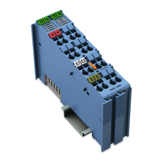
2AI 4-20mA HART Ex i 2-Channel Analog Input; HART; Intrinsically Safe, 2AI 4-20mA HART NE43 Ex i 2-Channel Analog Input; HART; NAMUR NE43; Intrinsically Safe
Brand:
WAGO
| Category:
I/O Systems
| Size: 2.87 MB
Table of Contents
Table of Contents
3
1 Notes about this Documentation
5
Validity of this Documentation
5
Copyright
5
Table 1: Variants
5
Symbols
6
Number Notation
8
Font Conventions
8
Table 2: Number Notation
8
Table 3: Font Conventions
8
2 Important Notes
9
Legal Bases
9
Subject to Changes
9
Personnel Qualifications
9
Use of the WAGO-I/O-SYSTEM 750 in Compliance with Underlying Provisions
9
Technical Condition of Specified Devices
10
Disposal
10
Safety Advice (Precautions)
11
3 Device Description
13
Table 4: Types of Application
14
Table 5: Compatibility List
15
View
16
Figure 1: View
16
Table 6: Legend for Figure "View
16
Connectors
17
Data Contacts/Local Bus
17
Figure 2: Data Contacts
17
Power Jumper Contacts/Field Supply
18
Figure 3: Power Jumper Contacts
18
Table 7: Legend for Figure "Power Jumper Contacts
18
CAGE CLAMP Connectors
19
Figure 4: CAGE CLAMP
19
Table 8: Legend for Figure "CAGE CLAMP
19
Display Elements
20
Operating Elements
20
Figure 5: Display Elements
20
Table 9: Legend for Figure "Display Elements
20
Schematic Diagram
21
Figure 6: Schematic Diagram
21
Technical Data
22
Device Data
22
Supply
22
Communication
22
Table 10: Technical Data - Device
22
Table 11: Technical Data - Supply
22
Table 12: Technical Data - Communication
22
Inputs
23
Table 13: Technical Data - Inputs
23
Explosion Protection
24
Connection Type
24
Table 14: Technical Data - Explosion Protection
24
Table 15: Technical Data - Field Wiring
24
Climatic Environmental Conditions
25
Table 16: Technical Data - Power Jumper Contacts
25
Table 17: Technical Data - Data Contacts
25
Table 18: Technical Data - Climatic Environmental Conditions
25
Approvals
26
Standards and Guidelines
28
4 Process Image
30
Basic Version of 750-484 I/O-Module
30
NAMUR Variant 750-484/000-001
31
Table 19: Process Values for the HART Module
31
Byte Mailbox
32
Table 20: Process Values for the HART Module, NAMUR NE43 Format
32
Table 21: Input Process Image or PROFIBUS Telegram
33
Table 22: Output Process Image or PROFIBUS Telegram
33
Table 23: Control Byte C0
33
Table 24: Status Byte S0 at 6-Byte Mailbox
34
HART Variable Per Channel
35
Table 25: PROFIBUS Telegram, Receive Direction, 1 HART Variable Per Channel
35
HART Variables Per Channel
36
Table 26: PROFIBUS Telegram, Receive Direction, 2 HART Variable Per Channel
36
HART Variables Per Channel
37
Table 27: PROFIBUS Telegram, Receive Direction, 3 HART Variable Per Channel
37
HART Variables Per Channel
38
Table 28: PROFIBUS Telegram, Receive Direction, 4 HART Variable Per Channel
38
Acyclic PROFIBUS Services
39
Table 29: PROFIBUS Telegram, Acyclic PROFIBUS Services
39
Table 30: PROFIBUS Telegram, Receive Direction, Acyclic PROFIBUS Services and Access to the Register Structure
40
Table 31: PROFIBUS Telegram, Send Direction, Acyclic PROFIBUS Services and Access to the Register Structure
40
Table 32: Control-Byte C0/C1
40
Table 33: Status Byte S0/S1 for Acyclic PROFIBUS Services
41
5 Mounting
42
Mounting Sequence
42
Inserting and Removing Devices
43
Inserting the I/O Module
43
Figure 7: Insert I/O Module (Example)
43
Figure 8: Snap the I/O Module into Place (Example)
43
Removing the I/O Module
44
Figure 9: Removing the I/O Module (Example)
44
6 Connect Devices
45
Connecting a Conductor to the CAGE CLAMP
45
Figure 10: Connecting a Conductor to a CAGE CLAMP
45
Power Supply Concept
46
Figure 11: Supply Principle Ex I
47
Figure 12: Overvoltage Categories
47
Table 34: Legend for Figure "Overvoltage Categories
47
Power Supply Concept in Marine Applications
48
Figure 13: Power Supply Concept, Category EMC1 (Marine Applications)
48
Table 35: Legend for Figure "Power Supply Concept, Category EMC1 (Marine Applications)
48
Figure 14: Power Supply Concept, Category EMC2 (Marine Applications)
49
Table 36: Legend for Figure "Power Supply Concept, Category EMC2 (Marine Applications)
49
Connection Example
50
Figure 15: Connection Example with 2 Passive HART Sensors
50
7 Function Description
51
8 Operating Modes
53
Table 37: Overview of Operating Modes
53
Table 38: Designation of Operating Modes in WAGO-I/O-CHECK
53
Table 39: Designation of Operating Modes in PROFIBUS GSD (Standard Module 750-484)
53
Setting the Operating Mode Parameters
54
Table 40: Designation of Operating Modes in PROFIBUS GSD (Variant 750-484/000-001)
54
Setting up Using WAGO-I/O-CHECK
55
Table 41: Setting the Operating Mode Parameters
55
Figure 16: WAGO-I/O-CHECK Context Menu „Settings
56
Figure 17: WAGO-I/O-CHECK Dialog Window (Example 750-484/000-001)
56
Setting up Via GSD
57
Figure 18: GSD Configuration (Example)
58
Figure 19: Parameterization Dialog for Selecting 750-484/000-001
59
Table 42: General Parameter Data
59
Table 43: Parameter Data for the HART Variables
60
Table 44: Parameter Data for Acyclic Access
60
Table 45: General Parameter Data
60
Table 46: Parameter Data for the HART Variables
61
Table 47: Parameter Data for Acyclic Access
62
FDT/DTM Concept
63
Figure 20: FDT/DTM Communication Principle
63
HART on PROFIBUS
65
9 Commissioning
65
Figure 21: Operation of HART Devices Via PROFIBUS
65
With PLC Library on All Compatible 75X-XXX Fieldbus
66
Couplers/Controllers
66
Communication on 75X-XXX Via PLC Library
66
Startup on the 75X-XXX Via PLC Library
67
Figure 22: Communication Example on the 75X-8Xx Controller Via Wagolibhart_0X.lib
67
Table 48: Required Software for Startup on 75X-XXX Via PLC Library
67
Figure 23: WAGO-I/O-PRO Project with Integrated "Wagolibhart_0X.lib" Library
68
With HART Dynamic Variables on PROFIBUS DP/V1 750-333 and 750-833
70
Table 49: Operating Mode for PROFIBUS DP/V1
70
Communication on the 750-333, -833 with Dynamic Variables
71
Commissioning on the 750-333, -833 with Dynamic Variables
71
Figure 24: System Overview with a PROFIBUS Fieldbus Coupler/Controller
71
Table 50: Software Required for the Commissioning on a 750-333, -833 with Dynamic Variables
72
FDT/DTM with the PROFIBUS DP/V1 750-333, 750-833
73
Figure 25: HW Config in STEP7
73
Communication on 750-333, -833 Via FDT/DTM
74
Figure 26: Example of a FDT/DTM Communication Via PROFIBUS
74
Commissioning on a 750-333, -833 Via FDT/DTM
75
Table 51: Software Required for the Commissioning on a 750-333, -833 Via FDT/DTM
75
Figure 27: Dialog Window "Device List
76
Figure 28: Dialog Window 750-333 Configuration, Register Device Information
77
Figure 29: Dialog Window 750-333 Configuration, Register Module Configuration
78
Figure 30: Dialog Window 750-333 Configuration, Register Parameterization
79
Figure 31: Dialog Window DTM Parameters
80
Figure 32: Dialog Window Detail: Setting for Channel 1
81
Figure 33: Channel Selection Dialog Window
81
Figure 34: Dialog Window Device List, Update
82
10 Use in Hazardous Environments
83
Marking Configuration Examples
84
Marking for Europe According to ATEX and Iecex
84
Figure 35: Marking Example According to ATEX and Iecex
84
Figure 36: Text Detail - Marking Example According to ATEX and Iecex
84
Table 52: Description of Marking Example According to ATEX and Iecex
85
Figure 37: Marking Example for Approved Ex I I/O Module According to ATEX and Iecex
86
Figure 38: Text Detail - Marking Example for Approved Ex I I/O Module According to ATEX and Iecex
86
Table 53: Description of Marking Example for Approved Ex I I/O Module According to ATEX and Iecex
87
Marking for America (NEC) and Canada (CEC)
88
Figure 39: Marking Example According to NEC
88
Figure 40: Text Detail - Marking Example According to NEC 500
88
Table 54: Description of Marking Example According to NEC 500
88
Figure 41: Text Detail - Marking Example for Approved Ex I I/O Module According to NEC 505
89
Table 55: Description of Marking Example for Approved Ex I I/O Module
89
Table 56: Description of Marking Example for Approved Ex I I/O Modules
89
Table 57: Description of Marking Example for Approved Ex I I/O Modules
90
Installation Regulations
91
Special Notes Regarding Explosion Protection
91
Special Notes Regarding ANSI/ISA Ex
93
11 Appendix
94
Information for Hart Library
94
CODESYS Library
94
PROFIBUS Gateway
94
List of Figures
95
List of Tables
97
Advertisement
WAGO 750-484 Manual (94 pages)
2 AI 4-20 mA HART Ex i 2-Channel-Analog Input Module 4-20 mA HART, Ex i
Brand:
WAGO
| Category:
I/O Systems
| Size: 3.99 MB
Table of Contents
Table of Contents
3
Copyright
5
Notes about this Documentation
5
Validity of this Documentation
5
Symbols
6
Number Notation
8
Font Conventions
8
Table 1: Number Notation
8
Table 2: Font Conventions
8
Important Notes
9
Legal Bases
9
Subject to Changes
9
Personnel Qualifications
9
Use of the WAGO-I/O-SYSTEM 750 in Compliance with Underlying Provisions
9
Technical Condition of Specified Devices
10
Safety Advice (Precautions)
11
Device Description
13
Table 3: Types of Application
14
Table 4: Compatibility List
15
Table 5: Legend for Figure "View
16
Figure 1: View
16
View
16
Connectors
17
Data Contacts/Internal Bus
17
Figure 2: Data Contacts
17
Power Jumper Contacts/Field Supply
18
Figure 3: Power Jumper Contacts
18
Table 6: Legend for Figure "Power Jumper Contacts
18
Table 7: Legend for Figure "CAGE CLAMP ® Connectors
19
CAGE CLAMP ® Connectors
19
Figure 4: CAGE CLAMP ® Connectors
19
Display Elements
20
Operating Elements
20
Figure 5: Display Elements
20
Table 8: Legend for Figure „Display Elements
20
Schematic Diagram
21
Figure 6: Schematic Diagram
21
Table 9: Technical Data - Device
22
Table 11: Technical Data - Communication
22
Table 10: Technical Data - Supply
22
Communication
22
Technical Data
22
Supply
22
Device Data
22
Inputs
23
Table 12: Technical Data - Inputs
23
Explosion Protection
24
Connection Type
24
Table 13: Technical Data - Explosion Protection
24
Table 14: Technical Data - Field Wiring
24
Table 17: Technical Data - Climatic Environmental Conditions
25
Table 15: Technical Data - Power Jumper Contacts
25
Table 16: Technical Data - Data Contacts
25
Climatic Environmental Conditions
25
Approvals
26
Standards and Guidelines
28
Process Image
30
AI 4-20 Ma + 6-Byte Mailbox
31
Table 18: Process Values for the HART Module
31
Table 21: Control Byte C0
32
Table 22: Status Byte S0
32
Table 20: Output Process Image
32
Table 19: Input Process Image
32
AI 4-20 Ma, 1 HART Variable Per Channel
33
AI 4-20 Ma, 2 HART Variables Per Channel
33
Table 23: PROFIBUS Telegram, 1 HART Variable Per Channel
33
AI 4-20 Ma, 3 HART Variables Per Channel
34
Table 24: PROFIBUS Telegram, 2 HART Variables Per Channel
34
AI 4-20 Ma, 4 HART Variables Per Channel
35
Table 25: PROFIBUS Telegram, 3 HART Variables Per Channel
35
Table 26: PROFIBUS Telegram, 4 HART Variables Per Channel
36
Table 29: Status Byte S0/S1
37
Table 27: PROFIBUS Telegram, Acyclic PROFIBUS Services
37
Table 28: Control Byte C0/C1
37
AI 4-20 Ma + Acyclic PROFIBUS Services
37
Appendix: Information for Hart Library
38
CODESYS Library
38
PROFIBUS Gateway
38
Mounting
39
Mounting Sequence
39
Inserting and Removing Devices
40
Inserting the I/O Module
40
Figure 7: Insert I/O Module (Example)
40
Figure 8: Snap the I/O Module into Place (Example)
40
Figure 9: Removing the I/O Module (Example)
41
Removing the I/O Module
41
Connect Devices
42
Connecting a Conductor to the CAGE CLAMP
42
Figure 10: Connecting a Conductor to a CAGE CLAMP
42
Power Supply Concept
43
Figure 11: Supply Principle Ex I
44
Figure 12: Overvoltage Categories
44
Table 30: Legend for Figure "Overvoltage Categories
44
Table 31: Legend for Figure "Power Supply Concept, Category EMC1
45
Figure 13: Power Supply Concept, Category EMC1 (Marine Applications)
45
Power Supply Concept in Marine Applications
45
Figure 14: Power Supply Concept, Category EMC2 (Marine Applications)
46
Table 32: Legend for Figure "Power Supply Concept, Category EMC2 (Marine Applications)
46
Connection Example
47
Figure 15: Connection Example with 2 Passive HART Sensors
47
Function Description
48
Operating Modes
49
Table 33: Overview of Operating Modes
49
Table 34: Setting the Operating Mode Parameters
50
Setting up Using WAGO-I/O-CHECK
50
Setting the Operating Mode Parameters
50
Figure 16: WAGO-I/O-CHECK Context Menu „Settings
51
Figure 17: WAGO-I/O-CHECK Dialog Window "Settings for 0750-0484
52
Figure 18: WAGO-I/O-CHECK Message for Successfully Parameterizing
52
Setting up Via GSD
53
Figure 19: GSD Configuration
54
Figure 20: Parameterization Dialog for Selecting 75X-484 2AI/4-20 Ma/Se/Ex I
55
Table 35: General Parameter Data
56
Table 36: Parameter Data for the HART Variables
56
FDT/DTM Concept
57
Table 37: Parameter Data for Acyclic Access
57
HART on PROFIBUS
58
Figure 21: FDT/DTM Communication Principle
58
Figure 22: Operation of HART Devices Via PROFIBUS
59
Description of Operation
60
With PLC Library on All Compatible 75X-XXX Couplers/Controllers
60
Communication with 75X-XXX Via PLC Library
61
Figure 23: Communication by Means of "Wagolibhart_0X.lib" Using a 75X-8Xx Controller as an Example
61
Commissioning on a 75X-XXX Via PLC Library
62
Table 38: Software Required for the Commissioning on a 75X-XXX Via PLC
62
Table 39: Operating Mode for PROFIBUS DP/V1
63
Figure 24: WAGO-I/O-PRO Project with Incorporated Library "Wagolibhart_0X.lib
63
With HART Dynamic Variables on PROFIBUS DP/V1 750-333 and 750-833
63
Communication on the 750-333, -833 with Dynamic Variables
65
Commissioning on the 750-333, -833 with Dynamic Variables
65
Figure 25: System Overview with a PROFIBUS Fieldbus Coupler/Controller
65
Table 40: Software Required for the Commissioning on a 750-333, -833 with
66
FDT/DTM with the PROFIBUS DP/V1 750-333, 750-833
67
Figure 26: HW Config in STEP7
67
Communication on 750-333, -833 Via FDT/DTM
68
Table 41: Software Required for the Commissioning on a 750-333, -833 Via
69
Figure 27: Example of a FDT/DTM Communication Via PROFIBUS
69
Commissioning on a 750-333, -833 Via FDT/DTM
69
Figure 28: Dialog Window "Device List
71
Figure 29: Dialog Window 750-333 Configuration, Register Device
72
Figure 30: Dialog Window 750-333 Configuration, Register Module
73
Figure 31: Dialog Window 750-333 Configuration, Register Parameterization
74
Figure 32: Dialog Window DTM Parameters
75
Figure 33: Dialog Window Detail: Setting for Channel 1
76
Figure 34: Channel Selection Dialog Window
76
Figure 35: Dialog Window Device List, Update
77
Use in Hazardous Environments
78
Figure 37: Text Detail - Marking Example According to ATEX and Iecex
79
Marking for Europe According to ATEX and Iecex
79
Figure 36: Marking Example According to ATEX and Iecex
79
Marking Configuration Examples
79
Table 42: Description of Marking Example According to ATEX and Iecex
80
Figure 38: Marking Example for Approved Ex I I/O Module According to ATEX and Iecex
81
Figure 39: Text Detail - Marking Example for Approved Ex I I/O Module According to ATEX and Iecex
81
Marking for America (NEC) and Canada (CEC)
82
Table 43: Description of Marking Example for Approved Ex I I/O Module According to ATEX and Iecex
82
Figure 40: Marking Example According to NEC
83
Figure 41: Text Detail - Marking Example According to NEC 500
83
Table 44: Description of Marking Example According to NEC 500
83
Table 45: Description of Marking Example for Approved Ex I I/O Module
84
Table 46: Description of Marking Example for Approved Ex I I/O Modules
84
Table 47: Description of Marking Example for Approved Ex I I/O Modules
85
Installation Regulations
86
Special Notes Regarding Explosion Protection
86
Special Notes Regarding ANSI/ISA Ex
88
Appendix
89
Rated Surge Voltage
89
Table 48: Rated Surge Voltage *)
89
List of Figures
90
List of Tables
92
Advertisement
Related Products
WAGO 750-481/003-000
WAGO 750-484/000-001
WAGO 750-433
WAGO 750-408
WAGO 750-461/000-007
WAGO 750-461/020-000
WAGO 750-455/040-000
WAGO 750-479
WAGO 750-462/000-011
WAGO 750-462/000-061
WAGO Categories
I/O Systems
Control Unit
Power Supply
Switch
Controller
More WAGO Manuals
Login
Sign In
OR
Sign in with Facebook
Sign in with Google
Upload manual
Upload from disk
Upload from URL