Table of Contents
Advertisement
Quick Links
HPE ProLiant e910 Server Blade User and
Maintenance Guide
Abstract
This document is for the person who installs, administers, and troubleshoots servers and storage systems.
Hewlett Packard Enterprise assumes you are qualified in the servicing of computer equipment and trained in
recognizing hazards in products with hazardous energy levels.
Part Number: P12855-002
Published: October 2019
Edition: 1
Advertisement
Table of Contents

Related Manuals for HPE ProLiant e910


Summary of Contents for HPE ProLiant e910
- Page 1 HPE ProLiant e910 Server Blade User and Maintenance Guide Abstract This document is for the person who installs, administers, and troubleshoots servers and storage systems. Hewlett Packard Enterprise assumes you are qualified in the servicing of computer equipment and trained in recognizing hazards in products with hazardous energy levels.
- Page 2 Notices The information contained herein is subject to change without notice. The only warranties for Hewlett Packard Enterprise products and services are set forth in the express warranty statements accompanying such products and services. Nothing herein should be construed as constituting an additional warranty. Hewlett Packard Enterprise shall not be liable for technical or editorial errors or omissions contained herein.
-
Page 3: Table Of Contents
DIMM slot locations......................................15 Processor, heatsink, and socket components............................16 Operations..........................17 Powering up the HPE Edgeline EL8000 Converged Edge chassis ......................17 Powering up the server blade......................................17 Installing the server blade into the chassis................................17 Removing the blade from the chassis..................................18 Removing the top cover........................................ - Page 4 Access options.........................................62 Configuring iLO access options..................................65 iLO default DNS name and user account.................................. 65 iLO licensing............................................... 65 iLO driver support...........................................66 Using HPE iLO 5........................67 iLO web interface overview.......................................67 iLO control icons........................................68 iLO navigation pane......................................69 iLO navigation pane remote console thumbnail..........................69 iLO default DNS name and user account..................................
- Page 5 General hardware problems..................................134 Display problems.........................................134 ROM issues..........................................134 Illustrated parts catalog....................135 Mechanical components........................................135 HPE ProLiant e910 server blade................................135 1U air baffle spare part....................................136 2U air baffle spare part....................................136 M.2 screw kit spare part....................................136 System components..........................................136 DIMMs spare part....................................... 137 System board spare part....................................
- Page 6 Server Blade options.......................................... 138 PCIe riser cards spare part.................................... 139 Network riser spare part....................................140 HPE ProLiant e910 NVMe M.2 enablement board spare part....................140 GPU Power Enablement kit...................................140 HPE e910 GPU cable kit....................................141 HPE e910 GPU PCIe 8-pin power cable kit............................141 HPE e910 GPU PCIe 8+6 pin power cable kit...........................
-
Page 7: Setup
Setup HPE ProLiant server setup checklist Install the hardware TIP: Did you know that HPE has QR codes on their servers? Scan one to access important information on your mobile device. After installing your new HPE ProLiant e910 Server Blade: 1. -
Page 8: Registering The Product
1. Boot your new server for the first time and start Intelligent Provisioning 2. Configure your hardware settings and install an operating system 3. Update the firmware Set up iLO The iLO default settings enable you to use most features without additional configuration. However, the configuration flexibility of iLO enables customization for multiple enterprise environments. -
Page 9: Component Identification
Component identification This chapter describes the external and internal server features and components. 1U Server blade components Item Description Half height, half length PCIe slot Release latch USB 3.0 ports Display Port connector Network connectors (QSFP+) 2U Server blade components Front panel Component identification... - Page 10 Item Description Top cover Half height, half length PCIe slot 3 Half height, half length PCIe slot 4 Release latch USB ports Display Port connector Network connectors (QSFP+) Full height, Full length PCIe slot 2 Full height, Full length PCIe slot 1 Top cover Bottom view when removed from the server blade Item...
-
Page 11: Server Blade Leds
Item Description Left side top cover Left PCIe riser PCIe riser slots Server blade LEDs 1U Server blade LEDs Item Description Status UID LED Blue = Blade id is enabled Flashing Blue = Blade firmware update is in progress and/or Integrated Remote Console (IRC) is in use Off = Blade id is not enabled Health LED... - Page 12 2U Server blade LEDs Item Description Status UID LED Blue = Blade id is enabled Flashing Blue = Blade firmware update is in progress and/or Integrated Remote Console (IRC) is in use Off = Blade id is not enabled Health LED Green = Normal operation Flashing amber = Degraded condition Flashing red = Critical condition...
-
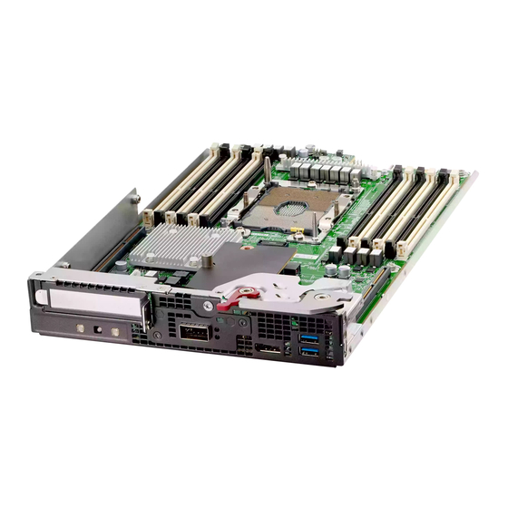
Page 13: System Board Components
System board components Item Description M.2 SSD slots PCIe riser slot Heatsink (Chipset) DIMMs Processor socket DIMMs Network mezzanine USB connectors Display Port connector System Battery DIMM label identification To determine DIMM characteristics, see the label attached to the DIMM. The information in this section helps you to use the label to locate specific information about the DIMM. - Page 14 Item Description Example Capacity 8 GB 16 GB 32 GB 64 GB 128 GB Rank 1R = Single rank 2R = Dual rank 4R = Quad rank 8R = Octal rank Data width on DRAM x4 = 4-bit x8 = 8-bit x16 = 16-bit Memory generation PC4 = DDR4...
-
Page 15: Dimm Slot Locations
R = RDIMM (registered) L = LRDIMM (load reduced) E = Unbuffered ECC (UDIMM) For more information about product features, specifications, options, configurations, and compatibility, see the HPE DDR4 SmartMemory QuickSpecs on the Hewlett Packard Enterprise website (http://www.hpe.com/support/ DDR4SmartMemoryQS). DIMM slot locations... -
Page 16: Processor, Heatsink, And Socket Components
Processor, heatsink, and socket components Item Description Heatsink nuts Processor carrier Pin 1 indicator Heatsink latch Alignment post Symbol also on the processor and frame. Component identification... -
Page 17: Operations
Powering up the HPE Edgeline EL8000 Converged Edge chassis If the HPE Edgeline EL8000 Converged Edge chassis is connected to a power source, it powers up automatically by default. Generally, it has to be powered up only after a manual shutdown. -
Page 18: Removing The Blade From The Chassis
Procedure 1. Align the blade and install it in the chassis: a. Insert the blade in the chassis. b. Close the latch on the server blade and secure it. 2. Optional: Lock the server blade. Removing the blade from the chassis Prerequisites Before performing this procedure, make sure that you have the T-15 Torx key available. -
Page 19: Removing The Top Cover
Procedure 1. Power down the system. 2. If locked, unlock the server blade. 3. Press and open the blade latch. 4. Remove the server blade. Removing the top cover The top cover is present only for the 2U server blade. Procedure 1. -
Page 20: Installing The Top Cover
Installing the top cover The top cover is present only for 2U HPE ProLiant e910 Server Blade. Procedure 1. Install the top cover. 2. Install the 2U server blade in the chassis. 3. Power up the server blade. Removing the air baffle for 1U server blade This air baffle is installed in the 1U server blade. -
Page 21: Installing The Air Baffle For 1U Server Blade
Procedure 1. Power down the server blade. 2. Remove the server blade from the chassis. 3. Remove the 1U air baffle. Installing the air baffle for 1U server blade Procedure 1. Install the air baffle. 2. Install the server blade in the chassis. 3. -
Page 22: Removing The Air Baffle For 2U Server Blade
Removing the air baffle for 2U server blade Procedure 1. Power down the server blade. 2. Remove the server blade from the chassis. 3. Remove the top cover. 4. Remove the 2U air baffle. Installing the air baffle for 2U server blade Procedure 1. -
Page 23: Powering Down The Server Blade
Use the virtual power button in the blade iLO web interface. • Enter the set power off b<slot#> at the chassis manager CLI. See the HPE Edgeline EL8000 Converged Edge System Chassis Manager CLI User Guide on the HPE website for details on CLI commands. -
Page 24: Hardware Options Installation
To view the warranty for your server and supported options, see Warranty information on page 179. PCIe riser option The 1U and 2U HPE ProLiant e910 Server Blades support the following PCIe riser cards: • HPE ProLiant e910 1U x16 half height, half length left riser card •... - Page 25 5. For 2U server blade, do the following: a. Disassemble the top cover. b. Remove the PCIe slot blank. c. Install the PCIe card: Hardware options installation...
-
Page 26: Nvme M.2 Enablement Option
Pull back the retention tab and align the PCIe card. Install the PCIe card and secure it with screw. 6. For 2U server blade, assemble the top cover. 7. For 2U server blade, install the top cover. 8. Install the server blade in the chassis. 9. -
Page 27: Installing The Nvme M.2 Enablement Option
Installing the NVMe M.2 enablement option Procedure 1. Power down the server blade. 2. Remove the server blade from the chassis. 3. For 2U server blade, do the following: a. Remove the top cover. b. Remove the air baffle. 4. For 1U server blade, install the NVMe M.2 enablement board: a. -
Page 28: M.2 Ssd Option
6. Install the NVMe M.2 SSD. 7. For 2U server blade, do the following: a. Install the air baffle. b. Install the top cover. 8. Install the server blade in the chassis. 9. Power up the server blade. M.2 SSD option The server blade system board supports NVMe or SATA M.2 SSDs of size 22x42mm or 22x80mm. -
Page 29: Installing The M.2 Sata Ssd
a. Remove the top cover. b. Remove the air baffle. 4. Do one of the following:. If installing the NVMe M.2 SSDs on the NVMe enablement board, install the NVMe enablement option • • If installing NVME M.2 SSDs on the system board, proceed with step 5. 5. - Page 30 • Plastic retention clips (2) • M.2 SATA SSD modules Procedure Power down the server blade. Remove the server blade from the chassis. For 2U server blade, do the following: a. Remove the top cover. b. Remove the air baffle. If installed, remove the NVMe M.2 SSD module.
- Page 31 Install the SATA M.2 SSD module: a. Insert the SSD module into the SSD slot at a 45° angle. b. Press rear side of the retention clip and carefully press the SSD down to horizontal position. c. Release the retention clip once the SATA M.2 SSD module is seated. Hardware options installation...
-
Page 32: Gpu Power Enablement Option
d. If you are installing a second SSD, repeat steps a–c. For 2U server blade, do the following: a. Install the air baffle. b. Install the top cover. Install the server blade in the chassis. 10. Power up the server blade. GPU power enablement option This option is available for the 2U server blade. - Page 33 Remove the PCIe slot blank. Do one of the following: • If an expansion card is installed, go to step 7. • Install the expansion card and secure it with screw. Install the GPU power enablement option. Hardware options installation...
-
Page 34: Network Riser Option
Assemble the top cover. Connect the GPU power cable and the signal cable. 10. Install the top cover. 11. Install the server blade in the chassis. 12. Power up the server blade. Network riser option Installing the network riser option Prerequisites Before you perform this procedure, make sure that you have a T-15 Torx screwdriver available. - Page 35 Procedure Power down the server blade. Remove the server blade from the chassis. For 2U server blade, do the following: a. Remove the top cover. b. Remove the air baffle. If installed, remove the metal plate from the front of the server blade. If installed, remove the NVMe M.2 enablement board.
- Page 36 • 2U server blade If removed, install the metal plate from the front of the server blade. Hardware options installation...
-
Page 37: Memory Options
If removed, install the NVMe M.2 enablement board. For 2U server blade, do the following: a. Install the air baffle. b. Install the top cover. 10. Install the server blade in the chassis. 11. Power up the server blade. Memory options IMPORTANT: This server does not support mixing LRDIMMs and RDIMMs. -
Page 38: Memory Subsystem Architecture
DIMM Specifications Type Rank Capacity (GB) Native Speed (MT/s) Voltage RDIMM Single 2933 RDIMM Dual 2933 RDIMM Dual 2933 LRDIMM Quad 2933 LRDIMM Octa 2933 Maximum memory capacity Maximum memory capacity is a function of DIMM capacity, number of installed DIMMs, memory type, and number of installed processors. -
Page 39: General Dimm Slot Population Guidelines
Channel Population order Slot number For the location of the slot numbers, see DIMM slot locations. This multichannel architecture provides enhanced performance in Advanced ECC mode. This architecture also enables Online Spare Memory mode. DIMM slots in this server are identified by number and by letter. Letters identify the population order. Slot numbers indicate the DIMM slot ID for spare replacement. - Page 40 For 2U server blade, remove the top cover. Open the DIMM slot latches. Install the DIMM . Install the air baffle: 1U server blade air baffle • 2U server blade air baffle • For 2U server blade, install the top cover. Install the server blade in the chassis.
-
Page 41: Cabling
Cabling Cable routing: GPU power enablement board Cable color Description Orange Signal cable Blue GPU power cable Cabling... -
Page 42: Configuration
Configuration Booting for the first time and accessing Intelligent Provisioning Using the Edgeline EL8000 Chassis Manager web interface to manage blade power The Edgeline EL8000 Chassis Manager web interface offers four ways to manage the blade power. Blade power can also be managed using the iLO 5 web interface. -
Page 43: Booting For The First Time
When you first power on a ProLiant Gen10 server, the server displays a list of booting subsystems and self tests. After the initial Power On Self Test (POST), the server displays the HPE ProLiant initialization screen. The checked icons at the bottom right represent each option that is present or installed on the server. -
Page 44: Configure Hardware Settings And Install An Operating System
Completing the Intelligent Provisioning setup wizard The first time you access Intelligent Provisioning on an HPE server, you must complete the first time setup wizard. These basic settings enable Intelligent Provisioning to display the proper language and time, set basic boot options, and communicate on your network. - Page 45 UEFI Optimized Boot Disabled For the best feature availability and ease of use, HPE recommends selecting UEFI Optimized Boot. You can switch to other boot modes as needed using configuration settings available after the wizard is complete. However, you will not be able to run Intelligent Provisioning again if you choose Legacy Boot Mode.
- Page 46 Enable DHCP Auto-Configuration. b. Leave Off disabled. Enabling the Off selection will make the server unavailable to iLO. HPE recommends leaving this setting disabled. 12. From the System Software Update menu, select Update from HPE.com. This selection allows Intelligent Provisioning to prompt you when updates are available, and then download any software updates for your server directly from the HPE website.
- Page 47 Select an Install Source from the list. The options and the required information and action for each are described in the following table. NOTE: Always On Intelligent Provisioning is limited to only using network install sources. Media type Required information/action DVD-ROM Media Insert the DVD.
-
Page 48: Update Your New Server's Firmware
Update your new server’s firmware Driver updates Most drivers are included with supported installed operating systems. However, some option cards may require you to download HPE supplied drivers. Check the documentation provided for the option cards for more information. Configuration... -
Page 49: Requirements For Iscsi Targeting
NOTE: If you are installing the drivers in a secure boot environment, see Secure Boot for Linux on HPE Servers for a complete set of instructions. HPE ProLiant e910 Server Blade Smart Component firmware updates HPE makes updates available for download that allow for feature additions and fixes. Download the firmware from the HPE website and execute the updates as described in the instructions. -
Page 50: Setting Up Ilo
What is iLO? iLO 5 is a remote server management processor embedded on the system boards of HPE ProLiant servers and Synergy compute modules. iLO enables the monitoring and controlling of servers from remote locations. iLO management is a powerful tool that provides multiple ways to configure, update, monitor, and repair servers remotely. -
Page 51: Learn More About Security Settings For Ilo 5
For more information, see the Top 10 security settings for HPE iLO 5 and Recommended Security Settings in HPE iLO 5 videos. Learn more about security settings for iLO 5 HPE developed a video to help teach you about security settings in iLO 5. To see the video, click one of the following links: HPE hosted video •... -
Page 52: Preparing To Set Up Ilo
IMPORTANT: Hewlett Packard Enterprise does not recommend setting the Minimum Password Length to fewer than eight characters unless you have a physically secure management network that does not extend outside the secure data center. Preparing to set up iLO Before setting up an iLO management processor, you must decide how to handle networking and security. The following questions can help you set up iLO: Procedure 1. -
Page 53: Ilo Access Security
• The iLO management port must be connected to a network that is connected to a DHCP server, and iLO must be on the network before power is applied. DHCP sends a request soon after power is applied. If the DHCP request is not answered when iLO first boots, it will reissue the request at 90-second intervals. -
Page 54: Agentless Management And Ams
• Management Service (AMS) driver. NOTE: If you are installing the drivers in a secure boot environment, see Secure Boot for Linux on HPE Servers for a complete set of instructions. Information made available when the AMS driver is installed... -
Page 55: Requirements For Iscsi Targeting
Do not disable the iLO Dedicated Network Port HPE iLO provides an option on the iLO Dedicated Network Port > General page, in the NIC Settings section for disabling the iLO Dedicated Network Port. Disabling this port also removes the ability for the iLO to communicate the Edgeline EL8000... -
Page 56: Ilo Setup With The Ilo 5 Configuration Utility
Chassis Manager. When the port is disabled, the Edgeline EL8000 Chassis Manager web interface will show the ProLiant e910 Server Blade as failed. No options to control the ProLiant e910 Server Blade will be active or able to show status messages. -
Page 57: Managing Local User Accounts With The Ilo 5 Configuration Utility
Managing local user accounts with the iLO 5 Configuration Utility Adding user accounts (iLO 5 Configuration Utility) Procedure (Optional) If you access the server remotely, start an iLO remote console session. Restart or power on the server. Press F9 in the server POST screen. The UEFI System Utilities start. -
Page 58: Logging In To Ilo For The First Time
Update the Login Name. Update the Password. a. Move the cursor to the Password box, and then press Enter. The Enter your new password box opens. b. Type the password, and then press Enter. The Confirm your new password box opens. c. -
Page 59: Managing The Server Power
Managing the server power The Virtual Power Button section on the Server Power page displays the current power state of the server, as well as options for remotely controlling server power. System Power indicates the state of the server power when the page is first opened. The server power state can be ON, OFF, or Reset. -
Page 60: Service Settings
The values you enter on the Access Settings page apply to all iLO users. Service settings You can configure the following settings in the Service section on the Access Settings page. Secure Shell (SSH) Allows you to enable or disable the SSH feature. SSH provides encrypted access to the iLO CLP. -
Page 61: Configuring Ilo Service Settings
If you customize the SNMP Trap Port , some SNMP monitoring applications might not work correctly with iLO unless those applications support the use of a nonstandard SNMP trap port. To use SNMP v3 with HPE SIM 7.2 or later, change the SNMP Trap Port value to 50005. IPMI/DCMI over LAN Allows you to send industry-standard IPMI and DCMI commands over the LAN. -
Page 62: Access Options
This option must be enabled when you register a server for Insight Remote Support central connect or Remote Support from HPE OneView. The following message is displayed if you try to use RIBCL when it is disabled: <?xml version="1.0"?>... - Page 63 When this setting is enabled (default), the iLO configuration options are available when you access the UEFI System Utilities. When this setting is disabled, the iLO configuration options are not available when you access the UEFI System Utilities. This setting cannot be enabled if option ROM prompting is disabled in the system BIOS. This option is called iLO 5 Configuration Utility in the UEFI System Utilities.
- Page 64 Serial Command Line Interface Speed Enables you to change the speed of the serial port for the CLI feature. The following speeds (in bits per second) are valid: 9600 (default) • For Synergy compute modules only: Ensure that this value is set to 9600. If you use another value, you cannot access the Serial Command Line Interface from the Synergy Console and Composer CLI.
-
Page 65: Configuring Ilo Access Options
Visit our list of standard features versus advanced features and how to obtain a license by visiting our iLO license guide at http://www.hpe.com/support/iLOLicenseGuide-en. To purchase an iLO Advanced License now, visit https:// www.hpe.com/us/en/product-catalog/detail/pip.332279.html. Setting up iLO... -
Page 66: Ilo Driver Support
Why register your iLO licenses? • Registration activates a unique HPE Support Agreement ID (SAID). Your SAID identifies you and the products you use. • You can obtain quicker HPE Support Services by using your SAID. • Obtain access to the HPE Support Center. -
Page 67: Using Hpe Ilo 5
Using HPE iLO 5 Some basic tasks and information are included here to get you started using HPE iLO. For more detailed iLO information, see the HPE iLO 5 User Guide at http://www.hpe.com/support/ilo-docs. When reliability is essential for your system health, HPE Integrated Lights-Out provides the automated intelligence to maintain complete server control from any places, anywhere, and ships with every ProLiant Server. -
Page 68: Ilo Control Icons
The color of this icon varies based on the current UID LED status. Language—Use this icon to select a language for the current iLO web interface session. • Use the Settings option to view or modify the language settings. Using HPE iLO 5... -
Page 69: Ilo Navigation Pane
To show the navigation pane when it is hidden, click the icon at the top-left corner of the iLO web interface. iLO navigation pane remote console thumbnail The navigation pane shows a thumbnail of the remote console. Using HPE iLO 5... -
Page 70: Ilo Default Dns Name And User Account
The iLO Overview page displays high-level details about the server and the iLO subsystem, as well as links to commonly used features. System information details • Server Name—The server name defined by the host operating system. Using HPE iLO 5... - Page 71 Chassis Serial Number—The serial number of the chassis that contains the server node. This value is displayed only for • server nodes in an HPE Apollo chassis. Product ID—This value distinguishes between different systems with similar serial numbers. The product ID is assigned •...
-
Page 72: System Status Details
Intrusion (the access panel is open). This value is displayed only on servers that are configured for chassis intrusion detection. iLO Date/Time—The internal clock of the iLO subsystem. • To navigate to the SNTP Settings page, click the iLO Date/Time link. Using HPE iLO 5... -
Page 73: Connection To Hpe Status
• Not registered—The server is not registered. • Unable to retrieve the HPE Remote Support information—The registration status could not be determined. Remote Support Registration Error—A remote support connection error occurred. • You can click the status value to navigate to the remote support registration page. -
Page 74: Redundancy Status
Failed Redundant—The device or subsystem is in a nonoperational state. • Failed—One or more components of the device or subsystem are nonoperational. • • Other—For more information, navigate to the System Information page of the component that is reporting this status. Using HPE iLO 5... -
Page 75: Viewing And Managing Firmware And Software
Out-of-band firmware update methods iLO web interface Download a supported firmware file and install it by using the iLO web interface. You can update firmware for a single server or an iLO Federation group. Using HPE iLO 5... -
Page 76: Ilo Firmware And Software Management
Add components from the iLO Repository to the installation queue. ◦ ◦ View and manage tasks in the installation queue. The best practice is to use SUM to manage the installation queue. For more information, see the SUM documentation. Using HPE iLO 5... -
Page 77: Viewing Installed Firmware Information
Innovation Engine (IE) firmware • Drive firmware • Power Supply firmware • Embedded Video Controller • Language packs • HPE Persistent Memory Firmware details The Installed Firmware page displays the following information for each listed firmware type: Using HPE iLO 5... -
Page 78: Replacing The Active System Rom With The Redundant System Rom
If the Update Firmware option is not displayed, click the ellipsis icon in the top-right corner of the iLO web interface, then click Update Firmware. Select the Local file or Remote file option. Depending on the option you selected, do one of the following: Using HPE iLO 5... - Page 79 You can also check the iLO firmware version on the Overview page. Supported firmware types Many firmware update types are supported, depending on the server platform. Some common examples follow: • • System ROM/BIOS • Chassis • Power Management Controller Using HPE iLO 5...
- Page 80 The BIN file from the iLO Online ROM Flash Component is required for updating the iLO firmware with the Flash Firmware or Group Firmware Update features. Procedure 1. Navigate to the following website: http://www.hpe.com/support/hpesc. 2. To locate and download the iLO Online ROM Flash Component file, follow the onscreen instructions. Download a Windows or Linux component.
-
Page 81: Viewing Software Information
Obtaining supported server firmware image files Procedure 1. Navigate to the following website: http://www.hpe.com/support/hpesc. 2. To locate and download an Online ROM Flash Component file, follow the onscreen instructions. 3. If you downloaded a Windows component: a. Double-click the downloaded file, and then click the Extract button. -
Page 82: Maintenance Windows
HPE Software details This section lists all the HPE software on the managed server. The list includes Hewlett Packard Enterprise and Hewlett Packard Enterprise-recommended third-party software that was added manually or by using the SPP. Name—The name of the software. - Page 83 To box. A calendar is displayed. d. Select the end date and time, and then click Done. Enter the date and time based on the local time on the client you are using to manage iLO. Using HPE iLO 5...
- Page 84 All tasks associated with the removed maintenance windows are canceled. Viewing maintenance windows Procedure 1. Click Firmware & OS Software in the navigation tree, and then click Maintenance Windows. 2. (Optional) To sort by a table column, click the column heading. Using HPE iLO 5...
-
Page 85: Ilo Repository
If you want to use the Update Recovery Set feature, a System Recovery Set must exist and contain the component you • want to update. Procedure 1. Click Firmware & OS Software in the navigation tree, and then click Upload to iLO Repository. Using HPE iLO 5... - Page 86 1. Click Firmware & OS Software in the navigation tree, and then click iLO Repository. 2. Click next to the component you want to install. The Install Component pane opens and prompts you to confirm the request. Using HPE iLO 5...
- Page 87 4. Select an end date and time, and then click Done. This value sets the expiration date and time for the tasks in the install set. The selected date and time are displayed in the To box. Using HPE iLO 5...
- Page 88 To change the sort order to ascending or descending, click the column heading again or click the arrow icon next to the column heading. 3. (Optional) To view detailed component information, click an individual component. iLO Repository storage details The Summary section of the iLO Repository page displays the following details about the iLO Repository storage use: Using HPE iLO 5...
-
Page 89: Installation Queue
You can add tasks to the queue by using the following methods: • Use the iLO Add to Queue pane. • Click on the Installation Queue page. • Click on the iLO Repository page. • Use SUM. Using HPE iLO 5... - Page 90 • 7. (Optional) If you selected a component in step 4, and the component exists in the System Recovery Set, select the Update Recovery Set check box to replace the existing component with the selected component. Using HPE iLO 5...
- Page 91 2. Select a start date and time, and then click Done. The selected date and time are displayed in the From box. 3. Click in the To box. A calendar is displayed. 4. Select an end date and time, and then click Done. Using HPE iLO 5...
- Page 92 3. To update the task name, enter a new name (up to 64 characters) in the Task name box. 4. Select a value in the Component or Command box. Using HPE iLO 5...
- Page 93 The installation queue is a first-in, first-out list of tasks, and you cannot create a task that will expire before an existing task will run. If you selected the Update Recovery Set check box, the component is updated after the task is initiated and completed successfully. Using HPE iLO 5...
- Page 94 1. Click Firmware & OS Software in the navigation tree, and then click the Installation Queue tab. 2. (Optional) To view detailed information, click an individual task. Queued task summary details State Status of the task. The possible values follow: Using HPE iLO 5...
- Page 95 Task results, if available. For example, The task completed successfully or The update failed with a component specific error. Retry the update after fixing the component error. Installable by The software that can initiate an update with the selected component. For example, iLO, Smart Update Manager or Smart Update Tool, or UEFI BIOS. Using HPE iLO 5...
-
Page 96: Managing The Server Power
Reset state. Prerequisites Virtual Power and Reset privilege Procedure 1. Click Power & Thermal in the navigation tree. The page opens with the Server Power tab selected. 2. Click one of the following buttons: Using HPE iLO 5... -
Page 97: Virtual Power Button Options
Active Health System data collection The Active Health System does not collect information about your operations, finances, customers, employees, or partners. Examples of information that is collected: • Server model and serial number • Processor model and speed Using HPE iLO 5... -
Page 98: Active Health System Log
You can also upload the log to the Active Health System Viewer. For more information, see the Active Health System Viewer documentation at the following website: http://www.hpe.com/support/ahsv-docs. Click the following link to view a video about this feature: iLO Active Health System and Viewer. -
Page 99: Downloading The Entire Active Health System Log
4. Click Download. 5. Save the file. 6. If you have an open support case, you can email the log file to gsd_csc_case_mngmt@hpe.com. Use the following convention for the email subject: CASE: <case number>. Files that are larger than 25 MB must be compressed and uploaded to an FTP site. If needed, contact Hewlett Packard Enterprise for FTP site information. -
Page 100: Clearing The Active Health System Log
Enterprise for FTP site information. 7. (Optional) Upload the file to the Active Health System Viewer. For more information, see http://www.hpe.com/servers/ahsv. Clearing the Active Health System Log If the log file is corrupted, or if you want to clear and restart logging, clear the Active Health System Log. -
Page 101: Starting The Integrated Remote Console
• A license that supports this feature is installed. For information about the available license types and the features they support, see the licensing documentation at the following website: http://www.hpe.com/support/ilo-docs. • The Remote Console feature is enabled on the Access Settings page. - Page 102 • A license that supports this feature is installed. For information about the available license types and the features they support, see the licensing documentation at the following website: http://www.hpe.com/support/ilo-docs. • The Remote Console feature is enabled on the Access Settings page.
- Page 103 Access the following keyboard shortcut that you can send to the remote server: CTRL+ALT+DEL. • • Access the following remote console virtual keys: ◦ CTRL—Control ◦ ESC—Escape ◦ CAPS—CapsLock NUM—NumLock ◦ ◦ L OS—Left OS-specific key Using HPE iLO 5...
- Page 104 Access the following keyboard shortcut that you can send to the remote server: CTRL+ALT+DEL. • Access the following remote console virtual keys: ◦ CTRL—Control ESC—Escape ◦ ◦ CAPS—CapsLock ◦ NUM—NumLock ◦ L OS—Left OS-specific key L ALT—Left ALT key ◦ Using HPE iLO 5...
- Page 105 • A license that supports this feature is installed. For information about the available license types and the features they support, see the licensing documentation at the following website: http://www.hpe.com/support/ilo-docs. • The Remote Console feature is enabled on the Access Settings page.
- Page 106 A license that supports this feature is installed. For information about the available license types and the features they support, see the licensing documentation at the following website: http://www.hpe.com/support/ilo-docs. The Remote Console feature is enabled on the Access Settings page.
- Page 107 A license that supports this feature is installed. For information about the available license types and the features they support, see the licensing documentation at the following website: http://www.hpe.com/support/ilo-docs. The Remote Console feature is enabled on the Access Settings page.
- Page 108 • A license that supports this feature is installed. For information about the available license types and the features they support, see the licensing documentation at the following website: http://www.hpe.com/support/ilo-docs. • The Remote Console feature is enabled on the Access Settings page.
- Page 109 A license that supports this feature is installed. For information about the available license types and the features they support, see the licensing documentation at the following website: http://www.hpe.com/support/ilo-docs. The Remote Console feature is enabled on the Access Settings page.
- Page 110 • A license that supports this feature is installed. For information about the available license types and the features they support, see the licensing documentation at the following website: http://www.hpe.com/support/ilo-docs. • The Remote Console feature is enabled on the Access Settings page.
-
Page 111: Integrated Remote Console Features
• A license that supports this feature is installed. For information about the available license types and the features they support, see the licensing documentation at the following website: http://www.hpe.com/support/ilo-docs. • The Remote Console feature is enabled on the Access Settings page. - Page 112 • A license that supports this feature is installed. For information about the available license types and the features they support, see the licensing documentation at the following website: http://www.hpe.com/support/ilo-docs. • The Remote Console feature is enabled on the Access Settings page.
- Page 113 A license that supports this feature is installed. For information about the available license types and the features they support, see the licensing documentation at the following website: http://www.hpe.com/support/ilo-docs. The Remote Console feature is enabled on the Access Settings page.
- Page 114 Using a virtual drive (physical drive on a client PC) Prerequisites • Remote Console privilege • A license that supports this feature is installed. For information about the available license types and the features they support, see the licensing documentation at the following website: http://www.hpe.com/support/ilo-docs. Using HPE iLO 5...
- Page 115 A license that supports this feature is installed. For information about the available license types and the features they support, see the licensing documentation at the following website: http://www.hpe.com/support/ilo-docs. The Remote Console feature is enabled on the Access Settings page.
- Page 116 • • An iLO license that supports using the remote console is installed. For information about the available license types and the features they support, see the licensing documentation at the following website: http://www.hpe.com/support/ilo- docs. • The operating system ISO file is available on the client you will use to run the remote console.
- Page 117 You can obtain drivers from the SPP or download them from the following website: http://www.hpe.com/support/ hpesc. Copy the driver to a USB key or a folder on the client where you will access the remote console. Start the remote console.
- Page 118 A license that supports this feature is installed. For information about the available license types and the features they support, see the licensing documentation at the following website: http://www.hpe.com/support/ilo-docs. The Remote Console feature is enabled on the Access Settings page.
- Page 119 • A license that supports this feature is installed. For information about the available license types and the features they support, see the licensing documentation at the following website: http://www.hpe.com/support/ilo-docs. Procedure 1. Click Remote Console & Media in the navigation tree.
- Page 120 • A license that supports this feature is installed. For information about the available license types and the features they support, see the licensing documentation at the following website: http://www.hpe.com/support/ilo-docs. • The Remote Console feature is enabled on the Access Settings page.
- Page 121 • A license that supports this feature is installed. For information about the available license types and the features they support, see the licensing documentation at the following website: http://www.hpe.com/support/ilo-docs. Procedure 1. Click Remote Console & Media in the navigation tree.
- Page 122 • A license that supports this feature is installed. For information about the available license types and the features they support, see the licensing documentation at the following website: http://www.hpe.com/support/ilo-docs. • The Remote Console feature is enabled on the Access Settings page.
- Page 123 • A license that supports this feature is installed. For information about the available license types and the features they support, see the licensing documentation at the following website: http://www.hpe.com/support/ilo-docs. Procedure 1. Click Remote Console & Media in the navigation tree.
-
Page 124: Ilo Alertmail
A license that supports this feature is installed. For information about the available license types and the features they support, see the licensing documentation at the following website: http://www.hpe.com/support/ilo-docs. The Remote Console feature is enabled on the Access Settings page. - Page 125 If you use a public or ISP SMTP server, make sure that the email addresses you enter are configured to allow less secure applications. Sender Domain or Email Address The sender (from) email address (up to 63 characters). This value can be formed by using the following methods: Using HPE iLO 5...
-
Page 126: Disabling Alertmail
Prerequisites • A license that supports this feature is installed. For information about the available license types and the features they support, see the licensing documentation at the following website: http://www.hpe.com/support/ilo-docs. • Configure iLO Settings privilege Using HPE iLO 5... -
Page 127: Viewing Chassis Information
The status of the power supply. The displayed value includes a status icon (OK, Degraded, Failed, or Other), and text that provides more information. The possible values follow: Unknown • Good, In Use • • Good, Standby Using HPE iLO 5... -
Page 128: Individual Power Supply Details
The status of the power supply. The displayed value includes a status icon (OK, Degraded, Failed, or Other), and text that provides more information. The possible values follow: • Unknown Good, In Use • Good, Standby • • General Failure • Over Voltage Failure Over Current Failure • Over Temperature Failure • Using HPE iLO 5... - Page 129 Model The power supply model number. Spare The spare power supply part number. Serial Number The power supply serial number. Using HPE iLO 5...
-
Page 130: Troubleshooting
3. If it is necessary to contact Hewlett Packard Enterprise, submit a support case through Active Health System Viewer. For more information, see the Active Health System Viewer user guide on the Hewlett Packard Enterprise website (http:// www.hpe.com/support/ahsv-docs). Important safety information Familiarize yourself with the safety information in the following sections before troubleshooting the system. - Page 131 This symbol on an RJ-45 receptacle indicates a network interface connection. WARNING: To reduce the risk of electric shock, fire, or damage to the equipment, do not plug telephone or telecommunications connectors into this receptacle. This symbol indicates the presence of a hot surface or hot component. If this surface is contacted, the potential for injury exists.
- Page 132 WARNING: To reduce the risk of electric shock or damage to the equipment: • Do not disable the power cord grounding plug. The grounding plug is an important safety feature. • Plug the power cord into a grounded (earthed) electrical outlet that is easily accessible at all times. •...
-
Page 133: Collecting Symptom Information
Obtain a record of all current ROM settings by running CONREP from Scripting Toolkit for Windows and Linux. b. Review the IML. c. Review the HPE iLO information on both the Overview and the System Information pages. d. Review the Diagnostics page. -
Page 134: Hardware Problems
PCIe card information is displayed incorrectly in RBSU Symptom When the HPE Ethernet 10/25GB 2P 661SFP28 Adapter is connected to configure 5900 switch, the PCIe card information is displayed incorrectly in RBSU. For more information, see the Customer Advisory at Hewlett Packard Enterprise Support Center. -
Page 135: Illustrated Parts Catalog
HPE ProLiant e910 Server Blade 1U air baffle 2U air baffle M.2 Screw kit* *Not shown HPE ProLiant e910 server blade Customer self repair on page 179: Mandatory Description Spare part number HPE ProLiant e910 2U Server Blade P13961-001 Illustrated parts catalog... -
Page 136: 1U Air Baffle Spare Part
• M.2 metal clips • M.2 black spacer for M.2 System components Hewlett Packard Enterprise continually improves and changes product parts. For complete and current supported spare parts information, see the Hewlett Packard Enterprise PartSurfer website: http://www.hpe.com/info/partssurfer Illustrated parts catalog... -
Page 137: Dimms Spare Part
Item Description System board Processor heatsink Processor DIMM DIMMs spare part Customer self repair on page 179: Optional Description Spare part number 8 GB, Single-rank x8 PC4-2933Y R P13208-001 16 GB, Dual-rank x8 PC4-2933Y R P13209-001 32 GB, Dual-rank x4 PC4-2933Y R P13210-001 64 GB, Quad-rank x4 PC4-2933Y L P13211-001... -
Page 138: Processor Heatsink Spare Part
For more information on removal and replacement procedures, see Removing and replacing the processor on page 164. Server Blade options Hewlett Packard Enterprise continually improves and changes product parts. For complete and current supported spare parts information, see the Hewlett Packard Enterprise PartSurfer website: http://www.hpe.com/info/partssurfer Illustrated parts catalog... -
Page 139: Pcie Riser Cards Spare Part
Network riser card (QSFP+) HPE e910 GPU Cable Kit* HPE e910 GPU PCIe 8-pin Power Cable Kit* HPE e910 GPU PCIe 8+6 pin Power Cable Kit* *Not Shown PCIe riser cards spare part Customer self repair on page 179: Optional... -
Page 140: Network Riser Spare Part
10G SPF+ Network riser P20589-001 For more information on removal and replacement procedures, see Removing and replacing the network riser on page 154. HPE ProLiant e910 NVMe M.2 enablement board spare part Customer self repair on page 179: Mandatory Description Spare part number Four-slot NVMe M.2 enablement board... -
Page 141: Hpe E910 Gpu Cable Kit
Customer self repair on page 179: Optional Description Spare part number HPE e910 GPU 8-pin power cable P21838-001 HPE e910 GPU PCIe 8+6 pin power cable kit Customer self repair on page 179: Optional Description Spare part number HPE e910 GPU 2x6-pin power cable... -
Page 142: Customer Self Repair
Customer self repair Hewlett Packard Enterprise products are designed with many Customer Self Repair (CSR) parts to minimize repair time and allow for greater flexibility in performing defective parts replacement. If during the diagnosis period Hewlett Packard Enterprise (or Hewlett Packard Enterprise service providers or service partners) identifies that the repair can be accomplished by the use of a CSR part, Hewlett Packard Enterprise will ship that part directly to you for replacement. - Page 143 REMARQUE: Certaines pièces Hewlett Packard Enterprise ne sont pas conçues pour permettre au client d'effectuer lui-même la réparation. Pour que la garantie puisse s'appliquer, Hewlett Packard Enterprise exige que le remplacement de la pièce soit effectué par un Mainteneur Agréé. Ces pièces sont identifiées par la mention "Non" dans le Catalogue illustré. Les pièces CSR sont livrées le jour ouvré...
- Page 144 Servizio di garanzia per i soli componenti La garanzia limitata Hewlett Packard Enterprise può includere un servizio di garanzia per i soli componenti. Nei termini di garanzia del servizio per i soli componenti, Hewlett Packard Enterprise fornirà gratuitamente le parti di ricambio. Per il servizio di garanzia per i soli componenti è...
- Page 145 componente CSR, Hewlett Packard Enterprise le enviará dicho componente directamente para que realice su sustitución. Los componentes CSR se clasifican en dos categorías: • Obligatorio—Componentes cuya reparación por parte del usuario es obligatoria. Si solicita a Hewlett Packard Enterprise que realice la sustitución de estos componentes, tendrá que hacerse cargo de los gastos de desplazamiento y de mano de obra de dicho servicio.
- Page 146 OPMERKING: Sommige Hewlett Packard Enterprise onderdelen zijn niet ontwikkeld voor reparatie door de klant. In verband met de garantievoorwaarden moet het onderdeel door een geautoriseerde Service Partner worden vervangen. Deze onderdelen worden in de geïllustreerde onderdelencatalogus aangemerkt met "Nee". Afhankelijk van de leverbaarheid en de locatie worden CSR-onderdelen verzonden voor levering op de eerstvolgende werkdag. Levering op dezelfde dag of binnen vier uur kan tegen meerkosten worden aangeboden, indien dit mogelijk is gezien de locatie.
- Page 147 Serviço de garantia apenas para peças A garantia limitada da Hewlett Packard Enterprise pode incluir um serviço de garantia apenas para peças. Segundo os termos do serviço de garantia apenas para peças, a Hewlett Packard Enterprise fornece as peças de reposição sem cobrar nenhuma taxa.
- Page 148 Customer self repair...
- Page 149 Customer self repair...
- Page 150 Customer self repair...
-
Page 151: Removal And Replacement Procedures
Removal and replacement procedures Safety considerations Before performing service procedures, review all the safety information. Preventing electrostatic discharge To prevent damaging the system, be aware of the precautions you must follow when setting up the system or handling parts. A discharge of static electricity from a finger or other conductor may damage system boards or other static-sensitive devices. This type of damage may reduce the life expectancy of the device. -
Page 152: Preparation Procedures
This symbol indicates that the component exceeds the recommended weight for one individual to handle safely. WARNING: To reduce the risk of personal injury or damage to the equipment, observe local occupational health and safety requirements and guidelines for manual material handling. These symbols, on power supplies or systems, indicate that the equipment is supplied by multiple sources of power. -
Page 153: Removing And Replacing The 2U Air Baffle
To replace the component, reverse the removal procedure. Removing and replacing the 2U air baffle Procedure 1. Power down the server blade. 2. Remove the server blade from the chassis. 3. Remove the top cover. 4. Remove the 2U air baffle. To replace the component, reverse the removal procedure. -
Page 154: Removing And Replacing The Network Riser
Removing and replacing the network riser Prerequisites Before you perform this procedure, make sure that you have a T-15 Torx screwdriver available. Procedure 1. Power down the server blade. 2. Remove the server blade from the chassis. 3. For 2U server blade, do the following: a. -
Page 155: Removing And Replacing The Nvme M.2 Enablement Board
To replace the component, reverse the removal procedure. Removing and replacing the NVMe M.2 enablement board Procedure 1. Power down the server blade. 2. Remove the server blade from the chassis. 3. For 2U server blade, do the following: a. Remove the top cover. b. -
Page 156: Removing And Replacing The Pcie Riser
• 1U server blade • 2U server blade To replace the component, reverse the removal procedure. Removing and replacing the PCIe riser Prerequisites Before you perform this procedure, make sure that you have a T-10 Torx screwdriver available. Procedure 1. Power down the server blade. 2. - Page 157 4. For 1U server blade, remove the PCIe riser. 5. For 2U server blade, do the following: a. Disassemble the top cover. b. Pull back the retention tabs and then remove the PCIe riser card. Removal and replacement procedures...
- Page 158 c. Remove the PCIe riser board: • Right PCIe riser board • Left PCIe riser board Removal and replacement procedures...
-
Page 159: Removing And Replacing The Gpu Power Enablement Board
To replace the component, reverse the removal procedure. Removing and replacing the GPU power enablement board The GPU power enablement board is installed for 2U e910 server blade only. Prerequisites Before you perform this procedure, make sure that you have a T-10 Torx screwdriver available. Procedure 1. -
Page 160: Removing And Replacing The Dimm
7. Remove the GPU power enablement board. To replace the component, reverse the removal procedure. Removing and replacing the DIMM To identify DIMM s installed in the server blade, see DIMM slot locations. Prerequisites Before replacing memory, read the memory configuration and population guidelines in the Memory options. Procedure 1. -
Page 161: Removing And Replacing The Heatsink Processor Assembly
1U server blade air baffle • 2U server blade air baffle • 5. Remove the DIMM. To replace the component, reverse the removal procedure. Removing and replacing the heatsink processor assembly This procedure shows a standard heatsink as an example. The removal process is the same for all heatsinks. Hewlett Packard Enterprise recommends identifying the processor, heatsink, and socket components before performing this procedure. - Page 162 For 2U server blade, remove the top cover. Observe the following cautions. CAUTION: Be sure to loosen each heatsink nut in the order indicated. Otherwise, damage might occur to the heatsink or processor. CAUTION: Install the processor heatsink assembly as soon as possible after removing it. Do not leave the processor socket unpopulated for extended periods of time.
- Page 163 CAUTION: Be sure to tighten each heatsink nut fully in the order indicated. Otherwise, boot failure or intermittent shutdowns might occur. c. Using a T-30 Torx screwdriver, tighten the nuts until they stop. Install the air baffle. • 1U server blade air baffle •...
-
Page 164: Removing And Replacing The Processor
11. Install the server blade in the chassis. 12. Power up the server blade. Removing and replacing the processor Hewlett Packard Enterprise recommends identifying the processor, heatsink, and socket components before performing this procedure. CAUTION: To prevent possible server malfunction and damage to the equipment, multiprocessor configurations must contain processors with the same part number. - Page 165 d. Unlatch the remaining corners of the frame. e. Separate the frame from the heatsink. To replace the processor: If reusing an existing heatsink, apply new thermal grease to the processor in the following pattern shown. If installing a new heatsink, the thermal grease is preapplied. Replace the processor assembly on the heatsink: a.
- Page 166 10. Install the processor heatsink assembly: a. Locate and align the Pin 1 indicator on the processor frame and the socket. b. Align the processor heatsink assembly with the heatsink alignment posts and gently lower it down until it sits evenly on the socket.
-
Page 167: Removing And Replacing The System Board
11. Install the air baffle. 1U server blade air baffle • • 2U server blade air baffle 12. For 2U server blade, install the top cover. 13. Install the server blade in the chassis. 14. Power up the server blade. Removing and replacing the system board Removing the system board Prerequisites... - Page 168 PCIe riser for 1U server blade • Network riser • • NVMe M.2 enablement board 7. Disconnect all cables from the system board. CAUTION: Be sure to loosen each heatsink nut in the order indicated. Otherwise, damage might occur to the heatsink or processor.
-
Page 169: Replacing The System Board
Replacing the system board Procedure 1. Install the spare system board. 2. Install the processor heatsink assembly: a. Locate and align the Pin 1 indicator on the processor frame and the socket. b. Align the processor heatsink assembly with the heatsink alignment posts and gently lower it down until it sits evenly on the socket. - Page 170 CAUTION: Be sure to tighten each heatsink nut fully in the order indicated. Otherwise, boot failure or intermittent shutdowns might occur. c. Using a T-30 Torx screwdriver, tighten the nuts until they stop. 3. Install all components removed from the failed system board. 4.
-
Page 171: Re-Entering The Server Serial Number And Product Id
5. For 2U server blade, install the top cover. 6. Install the server blade in the chassis. 7. Power up the server blade. 8. Ensure all firmware and embedded devices, is updated to the same versions to ensure that the latest drivers are being used. - Page 172 Prerequisites Before you perform this procedure make sure that you have a small flat-bladed, nonconductive tool available. Procedure 1. Power down the server blade. 2. Remove the server blade from the chassis. 3. For 2U server blade, remove the top cover. 4.
-
Page 173: Specifications
Specifications Environmental specifications Table 1: Standard specifications Specification Value — Temperature range Operating 0°C to 55°C (32°F to 131°F) Nonoperating -30°C to 60°C (-22°F to 140°F) Relative humidity (noncondensing) — Operating 8% to 90% at 28°C (82.4°F) maximum wet bulb temperature Non-Operating 5% to 95% at 38.7°C (101.7°F) maximum wet bulb temperature... -
Page 174: Mechanical Specifications
Depending on installed options, the server is configured with one of the following power supplies: • 1500W Hot Plug Power Supply • 1500W -48VDC Hot Plug Power Supply For detailed power supply specifications, see the QuickSpecs on the Hewlett Packard Enterprise website (http:// www.hpe.com/info/proliant/powersupply). 1500W Hot-plug Power Supply Specification Value Input requirements —... -
Page 175: 48Vdc Hot Plug Power Supply
Specification Value Rated input frequency 47Hz to 63 Hz Rated input current 15 A at 100 VAC 6.9 A at 240 VAC Maximum rated input power 1394 W at 90 VAC 1636 W at 264 VAC BTUs per hour 4757 at 90 VAC 5582 at 264 VAC Power supply output —... - Page 176 WARNING: To reduce the risk of electric shock or energy hazards: • This equipment must be installed by trained service personnel. • Connect the equipment to a reliably grounded secondary circuit source. A secondary circuit has no direct connection to a primary circuit and derives its power from a transformer, converter, or equivalent isolation device. •...
-
Page 177: Websites
Websites General websites Hewlett Packard Enterprise Information Library www.hpe.com/info/EIL Hewlett Packard Enterprise Edgeline Documentation www.hpe.com/info/edgeline-docs Hewlett Packard Enterprise Edgeline Information www.hpe.com/info/edgeline Hewlett Packard Enterprise OT Link and Workload Orchestrator Information http://www.hpe.com/info/OTLink-WO-FAQ Websites... -
Page 178: Support And Other Resources
Packard Enterprise Support Center More Information on Access to Support Materials page: www.hpe.com/support/AccessToSupportMaterials IMPORTANT: Access to some updates might require product entitlement when accessed through the Hewlett Packard Enterprise Support Center. You must have an HPE Passport set up with relevant entitlements. Support and other resources... -
Page 179: Customer Self Repair
HPE Proactive Care services www.hpe.com/services/proactivecare HPE Datacenter Care services www.hpe.com/services/datacentercare HPE Proactive Care service: Supported products list www.hpe.com/services/proactivecaresupportedproducts HPE Proactive Care advanced service: Supported products list www.hpe.com/services/proactivecareadvancedsupportedproducts Proactive Care customer information Proactive Care central www.hpe.com/services/proactivecarecentral Proactive Care service activation www.hpe.com/services/proactivecarecentralgetstarted... -
Page 180: Documentation Feedback
Hewlett Packard Enterprise is committed to providing documentation that meets your needs. To help us improve the documentation, send any errors, suggestions, or comments to Documentation Feedback (docsfeedback@hpe.com). When submitting your feedback, include the document title, part number, edition, and publication date located on the front cover of the document. -
Page 181: Acronyms And Abbreviations
Acronyms and abbreviations application program interface Customer Self Repair DDR4 double data rate-4 EurAsian Conformity HPE SSA HPE Smart Storage Administrator integrated Lights-out International Organization for Standardization LRDIMM load reduced dual in-line memory module PCIe Peripheral Component Interconnect Express power distribution unit... - Page 182 unit identification UEFI Unified Extensible Firmware Interface Acronyms and abbreviations...
Need help?
Do you have a question about the ProLiant e910 and is the answer not in the manual?
Questions and answers