Table of Contents
Advertisement
Quick Links
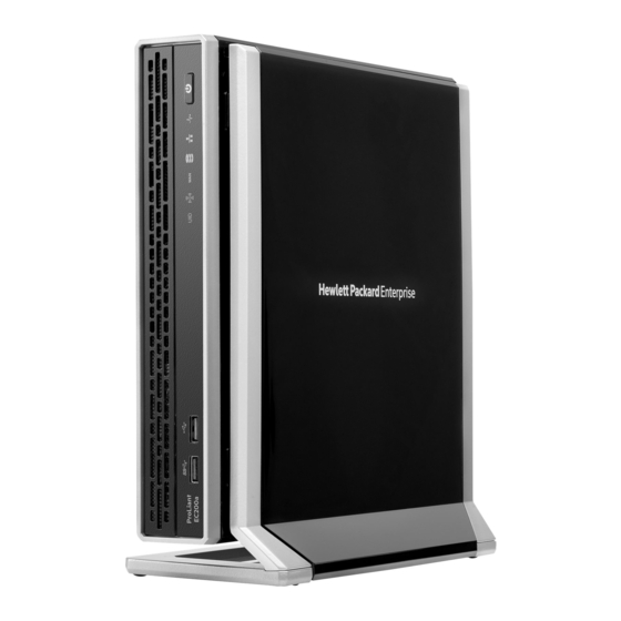
HPE ProLiant EC200a Managed
Hybrid Server
Maintenance and Service Guide
Abstract
This guide describes identification and maintenance procedures, specifications, and requirements for hardware components and software.
This guide is for an experienced service technician. Hewlett Packard Enterprise assumes that you are qualified in the servicing of computer
equipment, trained in recognizing hazards in products, and are familiar with weight and stability precautions.
Part Number: 856708-002
September 2016
Edition: 2
Advertisement
Table of Contents

Related Manuals for HPE ProLiant EC200a


Summary of Contents for HPE ProLiant EC200a
- Page 1 HPE ProLiant EC200a Managed Hybrid Server Maintenance and Service Guide Abstract This guide describes identification and maintenance procedures, specifications, and requirements for hardware components and software. This guide is for an experienced service technician. Hewlett Packard Enterprise assumes that you are qualified in the servicing of computer equipment, trained in recognizing hazards in products, and are familiar with weight and stability precautions.
- Page 2 © Copyright 2016 Hewlett Packard Enterprise Development LP The information contained herein is subject to change without notice. The only warranties for Hewlett Packard Enterprise products and services are set forth in the express warranty statements accompanying such products and services. Nothing herein should be construed as constituting an additional warranty.
-
Page 3: Table Of Contents
Contents Customer self repair ..........................5 Parts only warranty service ............................5 Illustrated parts catalog ........................15 Server and storage expansion unit components ....................15 Removal and replacement procedures ....................18 Safety considerations ............................. 18 Preventing electrostatic discharge....................... 18 Symbols on equipment ..........................18 Server warnings and cautions ........................ - Page 4 Component identification ........................52 Front panel components ............................52 Front panel LEDs and button ..........................52 Front panel LED power fault codes ......................53 Rear panel components ............................53 QR code label .............................. 54 Rear panel LEDs and button ..........................54 Recovery mode ............................
-
Page 5: Customer Self Repair
For more information about the Hewlett Packard Enterprise CSR program, contact your local service provider. For the North American program, go to the Hewlett Packard Enterprise CSR website (http://www.hpe.com/support/selfrepair). Parts only warranty service Your Hewlett Packard Enterprise Limited Warranty may include a parts only warranty service. Under the terms of parts only warranty service, Hewlett Packard Enterprise will provide replacement parts free of charge. - Page 6 Pour plus d'informations sur le programme CSR de Hewlett Packard Enterprise, contactez votre Mainteneur Agrée local. Pour plus d'informations sur ce programme en Amérique du Nord, consultez le site Web Hewlett Packard Enterprise (http://www.hpe.com/support/selfrepair). Service de garantie "pièces seules" Votre garantie limitée Hewlett Packard Enterprise peut inclure un service de garantie "pièces seules".
- Page 7 Per ulteriori informazioni sul programma CSR di Hewlett Packard Enterprise, contattare il centro di assistenza di zona. Per il programma in Nord America fare riferimento al sito Web (http://www.hpe.com/support/selfrepair). Servizio di garanzia per i soli componenti La garanzia limitata Hewlett Packard Enterprise può includere un servizio di garanzia per i soli componenti.
- Page 8 Weitere Informationen über das Hewlett Packard Enterprise Customer Self Repair Programm erhalten Sie von Ihrem Servicepartner vor Ort. Informationen über das CSR-Programm in Nordamerika finden Sie auf der Hewlett Packard Enterprise Website unter (http://www.hpe.com/support/selfrepair). Parts-only Warranty Service (Garantieservice ausschließlich für Teile) Ihre Hewlett Packard Enterprise Garantie umfasst möglicherweise einen Parts-only Warranty Service...
- Page 9 Packard Enterprise, póngase en contacto con su proveedor de servicios local. Si está interesado en el programa para Norteamérica, visite la página web de Hewlett Packard Enterprise CSR (http://www.hpe.com/support/selfrepair). Servicio de garantía exclusivo de componentes La garantía limitada de Hewlett Packard Enterprise puede que incluya un servicio de garantía exclusivo de componentes.
- Page 10 Neem contact op met een Service Partner voor meer informatie over het Customer Self Repair programma van Hewlett Packard Enterprise. Informatie over Service Partners vindt u op de Hewlett Packard Enterprise website (http://www.hpe.com/support/selfrepair). Garantieservice "Parts Only" Het is mogelijk dat de Hewlett Packard Enterprise garantie alleen de garantieservice "Parts Only" omvat.
- Page 11 Para obter mais informações sobre o programa de reparo feito pelo cliente da Hewlett Packard Enterprise, entre em contato com o fornecedor de serviços local. Para o programa norte-americano, visite o site da Hewlett Packard Enterprise (http://www.hpe.com/support/selfrepair). Serviço de garantia apenas para peças A garantia limitada da Hewlett Packard Enterprise pode incluir um serviço de garantia apenas para...
- Page 12 Customer self repair 12...
- Page 13 Customer self repair 13...
- Page 14 Customer self repair 14...
-
Page 15: Illustrated Parts Catalog
Hewlett Packard Enterprise continually improves and changes product parts. For complete and current supported parts information, see the Hewlett Packard Enterprise PartSurfer website (http://www.hpe.com/info/partssurfer). Only a Hewlett Packard Enterprise representative or service partner or MSP is authorized to replace all parts in this server. - Page 16 Item Description Spare part Customer self repair number (on page 5) Mandatory a) 4 TB 6G MDL drive 797519-001 b) 2 TB 6G MDL drive* 797523-001 Mandatory Storage expansion unit 858011-001 Mandatory Solid-state devices — — a) 128 GB SATA M.2 2280 SSD 863431-001 Mandatory Mandatory...
- Page 17 möchten, können bei diesem Service je nach den für Ihr Produkt vorgesehenen Garantiebedingungen zusätzliche Kosten anfallen. Nein—Einige Hewlett Packard Enterprise Teile sind nicht für Customer Self Repair ausgelegt. Um den Garantieanspruch des Kunden zu erfüllen, muss das Teil von einem Hewlett Packard Enterprise Servicepartner ersetzt werden.
-
Page 18: Removal And Replacement Procedures
Removal and replacement procedures Safety considerations Before performing service procedures, review all the safety information. Preventing electrostatic discharge To prevent damaging the system, be aware of the precautions you must follow when setting up the system or handling parts. A discharge of static electricity from a finger or other conductor may damage system boards or other static-sensitive devices. -
Page 19: Server Warnings And Cautions
The Managed Hybrid Service contract includes all of the required onsite server maintenance, provided that the server has been supplied as a part of the HPE Easy Connect solution. Do not attempt to open the chassis or tamper with it in any way. Any such action is a breach of the Managed Hybrid Service contract. -
Page 20: Prepare The Server For Hardware Replacement
Verify that the server data has been recently backed up. You can view the current backup status from the User Control Console Dashboard. For more information on this console, see the HPE ProLiant Easy Connect User Control Console Guide on the Hewlett Packard Enterprise website (http://www.hpe.com/support/EC-UCCG). -
Page 21: Remove The Server From The Mounting/Docking Hardware
If the system does not power down after the LAN, WAN, and WiFi LEDs stop flashing, contact the HPE ProLiant Easy Connect Support (https://support.prolianteasyconnect.com). Verify that the system power LED on the server or servers where the power button was pressed is ("Front panel LEDs and... - Page 22 Remove the server from the wall mount. Remove the server from the storage expansion unit Before you perform this procedure, make sure that you have a No. 2 Phillips screwdriver available. Hold the top side of the server and the bottom side of the storage expansion unit, and then carefully turn the assembly over to access the bottom side of the storage expansion unit.
-
Page 23: Remove The Access Panel
Remove the server from the storage expansion unit. Remove the access panel Before you perform this procedure, make sure that you have a No. 2 Phillips screwdriver available. Loosen the captive screws. Slide the access panel toward the front of the server, and then lift it from the server. Remove the communication board Before you perform this procedure, make sure that you have a No. - Page 24 Retain the screws for later use. Remove the RJ-45 port spacer. Retain the blank for future use. Removal and replacement procedures 24...
-
Page 25: Remove The Server Drive Assemblies
Remove the communication board. Remove the server drive assemblies Before you perform this procedure, make sure that you have a No. 2 Phillips screwdriver available. Release the server drive SATA cables from the middle frame: Press the release button on the SATA cables, and then disconnect the cables from the system board. -
Page 26: Remove The Middle Frame
— Removing the server drive 2 — Removing the server drive 1 Remove the middle frame Before you perform this procedure, make sure that you have the following tools available: • T-15 Torx screwdriver • Flathead screwdriver To remove the component: If installed, remove the communication board (on page 23). - Page 27 Retain the screw for later use. Remove the RJ-45 port blank. Retain the blank for future use. Remove the RJ-11 port blank. Removal and replacement procedures 27...
-
Page 28: Prepare The Server For Operation
Retain the blank for future use. Remove the server drive assemblies (on page 25). Remove the middle frame from the server: Remove the screws and standoffs securing the middle frame. Lift the middle frame from the system board. Prepare the server for operation Depending on what hardware was replaced, do one or more of the following: If removed, install the middle frame (on page 29). -
Page 29: Install The Middle Frame
If removed, install the server drive assemblies (on page 30). If removed, install the communication board (on page 32). If removed, install the access panel (on page 34). If the server was removed from the cradle, wall mount, or storage expansion unit: Install the server in the cradle (on page 34). -
Page 30: Install The Server Drive Assemblies
Install the first six screws according to the numbering indicated on the middle frame. Install the remaining screws and standoffs on the middle frame. Install the server drive assemblies Before you perform this procedure, make sure that you have a No. 2 Phillips screwdriver available. Install the server drive 1, and then install the server drive 2 by using the same procedure: Connect the SATA-power Y-cable to the drive. - Page 31 Tighten the captive screws. — Installing the server drive 1 — Installing the server drive 2 Secure the drive SATA-power Y-cables in the middle frame: Connect the server drive 2 SATA cable to the system board. Connect the server drive 1 SATA cable to the system board. Removal and replacement procedures 31...
-
Page 32: Install The Communication Board
Secure the cables in the middle frame cable clips. Install the communication board Before you perform this procedure, make sure that you have a No. 2 Phillips screwdriver available. Align the rear screw holes of the communication board to the middle frame, and then press down on the front end of the board until it clicks into place. - Page 33 Ensure that the spacer is flush against the rear panel surface. Align the rear screw holes of the RJ-45 port bracket to the middle frame, and then install the screws according to the numbering indicated on the bracket. Removal and replacement procedures 33...
-
Page 34: Install The Access Panel
Install the communication board screws. Install the access panel Before you perform this procedure, make sure that you have a No. 2 Phillips screwdriver available. Slide the access panel toward the rear of the server. Tighten the captive screws. Install the server in the cradle Place the cradle on a level, sturdy surface. -
Page 35: Install The Server In The Wall Mount
Open the latches on the cradle. Place the server in a vertical position with the rear panel facing the cradle latches. Attach the server to the cradle: Insert the two hooks on the right side of the cradle into the corresponding openings on the bottom of the server. -
Page 36: Install The Server On The Storage Expansion Unit
To ensure that the retention latch fully engages with the server, push the back edge of the server against the wall mount. Installing the server in the wall mount when the power source location is lower than the wall mount. Installing the server in the wall mount when the power source location is higher than the wall mount. -
Page 37: Power Up Procedure
Tilt the server down until the two posts on top of the storage expansion unit seat into the corresponding openings on the bottom of the server. This docking action attaches the server to the storage expansion unit. However, the assembly is NOT yet locked into place. -
Page 38: Replacing The Storage Expansion Unit
The server exits standby mode and full power is applied to the system. Verify that the system power LED on the server is white ("Front panel LEDs and button" on page 52). Power up a clustered system Press the Power On/Standby button on both servers within 5 minutes of each other. The servers exit standby mode and full power is applied to the systems. -
Page 39: Replacing The Solid-State Device
Open, and then remove the drive bay cover. Remove the drive. Replacing the solid-state device Process overview: Prepare the server for hardware replacement (on page 20). Remove the solid-state device (on page 39). To replace the solid-state device, reverse the removal procedure. Prepare the server for operation (on page 28). -
Page 40: Replacing A Dimm
Remove the cover. Remove the solid-state device. Replacing a DIMM Process overview: Prepare the server for hardware replacement (on page 20). Remove the access panel (on page 23). Remove the DIMM (on page 40). To replace the DIMM, reverse the removal procedure. Prepare the server for operation (on page 28). -
Page 41: Replacing The Communication Board
Remove the DIMM. Replacing the communication board Process overview: Prepare the server for hardware replacement (on page 20). Remove the access panel (on page 23). Remove the communication board (on page 23). Install the communication board spare ("Install the communication board"... -
Page 42: Replacing The Drive Sata-Power Y-Cable
Remove the drive from the carrier. Replacing the drive SATA-power Y-cable Process overview: Prepare the server for hardware replacement (on page 20). Remove the access panel (on page 23). If installed, remove the communication board (on page 23). Remove the server drive assemblies (on page 25). Remove the drive SATA-power Y-cable (on page 42). -
Page 43: Replacing The Server Fan
Replacing the server fan Process overview: Prepare the server for hardware replacement (on page 20). If installed, remove the communication board (on page 23). Remove the server drive assemblies (on page 25). Remove the middle frame (on page 26). Remove the fan ("Remove the server fan"... -
Page 44: Fan Parts
Remove the rubber caps. Fan parts Item Description Fan blade Rubber caps Fan guard Removal and replacement procedures 44... -
Page 45: Install The Server Fan
Install the server fan Attach the rubber caps to the fan. Install the fan. The fan guard side of the fan must face the ventilation slots of the chassis. In this position, the airflow arrow markings on the fan point to the chassis exterior. Connect the fan cable to the system board ("System board components"... -
Page 46: Remove The System Battery
Prepare the server for operation (on page 28). Remove the system battery Before you perform this procedure, make sure that you have a small flat-nose plier available. Locate the battery on the system board ("System board components" on page 56). Slightly push the metal tab, and then use the small flat-nose pliers to remove the system battery from its socket. -
Page 47: Replacing The System Board Assembly
Detach the other end of the cable from the adhesive pad. Replacing the system board assembly Process overview: Prepare the server for hardware replacement (on page 20). Remove the solid-state device (on page 39). Remove the access panel (on page 23). If installed, remove the communication board (on page 23). -
Page 48: Install The System Board Assembly
Remove the screw on the fin base end of the heatsink. Remove the system board assembly. Install the system board assembly Before you perform this procedure, make sure that you have a T-15 Torx screwdriver available. Removal and replacement procedures 48... -
Page 49: Re-Entering The Server Serial Number And Product Id
Install the system board assembly. Secure the screw on the fin base end of the heatsink. Re-entering the server serial number and product ID After you replace the system board, you must re-enter the server serial number and the product ID: During the server startup sequence, press the F9 key to access UEFI System Utilities. - Page 50 The following warning appears: Warning: The Product ID should ONLY be modified by qualified service personnel. This value should always match the Product ID located on the chassis. Enter the product ID and press the Enter key. To confirm exiting System Utilities, press the F10 key. The server automatically reboots.
-
Page 51: Troubleshooting
Troubleshooting Troubleshooting resources The HPE ProLiant Easy Connect Managed Hybrid Server Troubleshooting Guide (http://www.hpe.com/support/EC-TSG) provides procedures for resolving common problems and comprehensive courses of action for fault isolation and identification, issue resolution, and software maintenance. For the latest server support information, see the Hewlett Packard Enterprise ProLiant Easy Connect Support Portal (https://support.prolianteasyconnect.com). -
Page 52: Component Identification
Health LED Solid white = Normal Flashing amber = System degraded Flashing red (1 flash per second) = System critical If the health LED indicates a degraded or critical state, contact HPE ProLiant Easy Connect Support (https://support.prolianteasyconnect.com). Component identification 52... -
Page 53: Front Panel Led Power Fault Codes
Power On/Standby Solid white = System on button and system Flashing white = Performing power on sequence power LED Solid red = System in standby Flashing red = Unsuccessful power on sequence. When the 120 W power adapter is connected to a server that is attached to a storage expansion unit, the system power LED flashes red. -
Page 54: Qr Code Label
Item Description Video connector To reduce the risk of electric shock, fire, or damage to the equipment, only devices that are made of fire-retardant material can be connected to this video connector (VGA). Kensington security slot Dedicated iLO management connector LAN connector WAN connector * These connectors are present in the communication board option. -
Page 55: Recovery Mode
Recovery mode Do not initiate recovery mode unless directed by HPE ProLiant Easy Connect Support (https://support.prolianteasyconnect.com). During recovery mode, the system will first attempt to perform a graceful shutdown of the operating system (soft reset). If the soft reset attempt fails, the system will proceed to a hard reset. -
Page 56: System Board Components
Drive 2 power connector System maintenance switch Ambient temperature sensor connector Drive 1 power connector System maintenance switch Do not change any of the system maintenance switch settings unless directed by HPE ProLiant Easy Connect Support (https://support.prolianteasyconnect.com). Position Default Function Off = iLO 4 security is enabled. -
Page 57: Drive Numbering
Position Default Function Reserved Off = Power-on password is enabled. On = Power-on password is disabled. Off = No function On = ROM reads system configuration as invalid. — Reserved S7, S8, S9, S10, S11, and S12 You can access the redundant ROM by setting S1, S5, and S6 to On. When the system maintenance S6 switch is set to the On position, the system will erase all system configuration settings from both CMOS and NVRAM on the next reboot. -
Page 58: Kensington Security Slot Locations
Kensington security slot locations • Kensington security slot for a server in the desktop position—Use a Kensington cable lock. • Kensington security slot for a server installed in the cradle—Use a Kensington cable lock. • Kensington security slot in the wall mount—Use a Kensington noncable lock or a cable lock that includes a wall mount anchor. -
Page 59: Fan Location
• Kensington security slot in the storage expansion unit—Use a Kensington cable lock. Fan location • Fan location in the server Component identification 59... - Page 60 • Fan location in the storage expansion unit Component identification 60...
-
Page 61: Cabling
Cabling Cabling overview This section provides guidelines that help you make informed decisions about cabling the server and hardware options to optimize performance. CAUTION: When routing cables, always be sure that the cables are not in a position where they can be pinched or crimped. Drive cabling Item Description... -
Page 62: Fan Cabling
Fan cabling Ambient temperature sensor cabling Cabling 62... -
Page 63: Specifications
Specifications Environmental specifications Specification Value — Temperature range 10°C to 35°C (50°F to 95°F) Operating -30°C to 65°C (-22°F to 149°F) Nonoperating — Relative humidity (noncondensing) Maximum wet bulb temperature of 28°C Operating (82.4°F) = 10% to 90% Maximum wet bulb temperature of 38.7°C Nonoperating (101.7°F) = 0% to 95% All temperature ratings shown are for sea level. -
Page 64: Support And Other Resources
Product-specific reports and logs • Add-on products or components • Third-party products or components Websites • Hewlett Packard Enterprise Information Library (http://www.hpe.com/info/enterprise/docs) • Hewlett Packard Enterprise Support Center (http://www.hpe.com/support/hpesc) • Contact Hewlett Packard Enterprise Worldwide (http://www.hpe.com/assistance) • Customer Self Repair (http://www.hpe.com/support/selfrepair) -
Page 65: Acronyms And Abbreviations
Acronyms and abbreviations Customer Self Repair Integrated Lights-Out large form factor midline (HPE Midline drive family) managed service provider NVRAM nonvolatile memory QR code quick response code RBSU ROM-Based Setup Utility SATA serial ATA solid-state device UEFI Unified Extensible Firmware Interface... -
Page 66: Documentation Feedback
Hewlett Packard Enterprise is committed to providing documentation that meets your needs. To help us improve the documentation, send any errors, suggestions, or comments to Documentation Feedback (mailto:docsfeedback@hpe.com). When submitting your feedback, include the document title, part number, edition, and publication date located on the front cover of the document. For online help content, include the product name, product version, help edition, and publication date located on the legal notices page. -
Page 67: Index
Hewlett Packard Enterprise contact information 5, cradle, removing server from 21 CSR (customer self repair) 5 Hewlett Packard Enterprise Technical Support 5, 64 HPE ProLiant Easy Connect Support Portal 64 humidity 63 dedicated iLO management connector 53 dimensions and weight 63... - Page 68 49 warnings 19 requirements, airflow 19 warranty information 5 reset button, location 53 website, Hewlett Packard Enterprise 64 website, HPE ProLiant Easy Connect Support Portal 64 weight 63 safety considerations 18 Wi-Fi LED 52 safety information 18...
Need help?
Do you have a question about the ProLiant EC200a and is the answer not in the manual?
Questions and answers