Table of Contents
Advertisement
HPE Apollo 6500 Gen10 / HPE ProLiant
XL270d Gen10 Server User Guide
Abstract
This document is for the person who installs, administers, and troubleshoots servers and storage
systems. Hewlett Packard Enterprise assumes you are qualified in the servicing of computer
equipment and trained in recognizing hazards in products with hazardous energy levels.
Part Number: P05100-002
Published: June 2018
Edition: 2
Advertisement
Table of Contents

Subscribe to Our Youtube Channel
Related Manuals for HPE Apollo 6500 Gen10


Summary of Contents for HPE Apollo 6500 Gen10
- Page 1 HPE Apollo 6500 Gen10 / HPE ProLiant XL270d Gen10 Server User Guide Abstract This document is for the person who installs, administers, and troubleshoots servers and storage systems. Hewlett Packard Enterprise assumes you are qualified in the servicing of computer equipment and trained in recognizing hazards in products with hazardous energy levels.
- Page 2 © Copyright 2018 Hewlett Packard Enterprise Development LP Notices The information contained herein is subject to change without notice. The only warranties for Hewlett Packard Enterprise products and services are set forth in the express warranty statements accompanying such products and services. Nothing herein should be construed as constituting an additional warranty. Hewlett Packard Enterprise shall not be liable for technical or editorial errors or omissions contained herein.
-
Page 3: Table Of Contents
Warnings and cautions........................26 Determining power and cooling configurations..................28 Power requirements........................28 HPE Modular Cooling System 300 and Apollo IT and CDU Rack system......28 HPE Apollo System Manager....................28 Hot-plug power supply calculations..................29 Connecting a DC power cable to a DC power source............29 Optimum environment........................ - Page 4 Installing a PCIe riser board in the SXM2 GPU module..............59 Installing a PCIe riser board in the PCIe GPU module..............60 Installing a processor heatsink assembly..................61 Installing the HPE Smart Storage Battery..................64 Cabling......................66 SAS/SATA cabling..........................66 NVMe cabling............................ 67 AC power cabling..........................
- Page 5 Selecting the boot mode ......................77 Secure Boot..........................78 Launching the Embedded UEFI Shell ..................79 HPE Smart Storage Administrator.....................79 USB support............................80 External USB functionality...................... 80 Redundant ROM support........................80 Safety and security benefits....................80 Keeping the system current.......................80 Updating firmware or system ROM..................80 Drivers............................
-
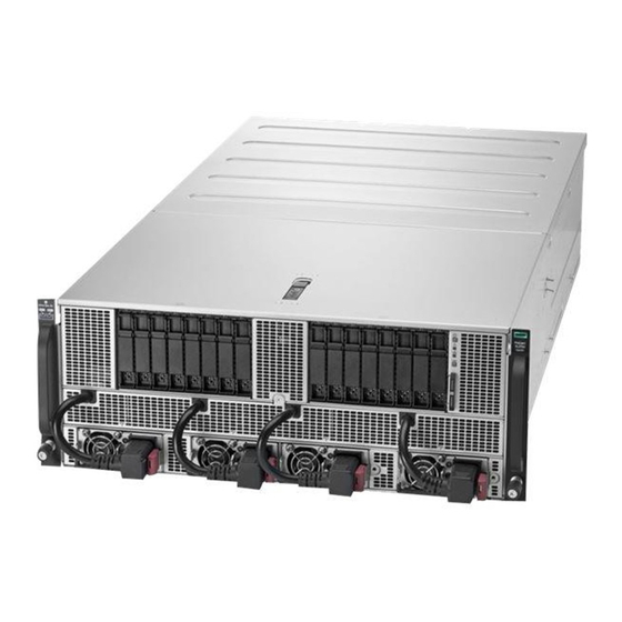
Page 6: Component Identification
Drive bay 1 (for optional 8SFF drive cage) Drive bay 2 (for optional 8SFF drive cage) Serial label pull tab Power supply bays 3 and 4 (for optional HPE 2200 W Platinum Hot Plug Power Supplies) HPE 2200W Platinum Hot Plug Power Supplies 1... -
Page 7: Uid Button Functionality
The UID button can be used to display the Server Health Summary when the server will not power on. For more information, see the latest HPE iLO User Guide on the Hewlett Packard Enterprise website. Front panel LED power fault codes The following table provides a list of power fault codes, and the subsystems that are affected. -
Page 8: Rear Panel Components (Sxm2 Gpu Module)
LED behavior Memory 3 flashes Riser board PCIe slots 4 flashes FlexibleLOM 5 flashes Removable HPE Smart Array SR Gen10 controller 6 flashes System board PCIe slots 7 flashes Power backplane or storage backplane 8 flashes Power supply 9 flashes... -
Page 9: Rear Panel Components (Pcie Gpu Module)
Rear panel components (PCIe GPU module) Item Description GPU module Low-profile PCIe Gen3 slots 9-12 (GPU module) GPU module latches Full Height Half Length PCIe Gen3 slot (system board module) System board module latches System board module Dedicated iLO management port Embedded 4 x 1GbE Network Adapter Video connector USB 3.0 ports... -
Page 10: System Board Components
System board components Item Description Storage connector Midplane connectors NVMe drive ports Internal communication port PCIe riser cage connector System battery Type -a storage controller connector FlexibleLOM connector M.2 riser connector iLO USB connector Internal USB 3.0 connector Table Continued System board components... -
Page 11: System Maintenance Switch Descriptions
Item Description X4 embedded SATA ports 1-3 System Maintenance Switch System maintenance switch descriptions Position Default Function Off = security is enabled. On = security is disabled. Off = System configuration can be changed. On = System configuration is locked. Reserved Reserved Off = Power-on password is enabled. -
Page 12: Dimm Slot Locations
DIMM slot locations DIMM slots are numbered sequentially (1 through 12) for each processor. The supported AMP modes use the letter assignments for population guidelines. The arrow indicates the front of the server. DIMM label identification To determine DIMM characteristics, see the label attached to the DIMM. The information in this section helps you to use the label to locate specific information about the DIMM. - Page 13 DIMM type R = RDIMM (registered) L = LRDIMM (load reduced) E = Unbuffered ECC (UDIMM) For more information about product features, specifications, options, configurations, and compatibility, see the product QuickSpecs on the Hewlett Packard Enterprise website (http://www.hpe.com/info/qs). Component identification...
-
Page 14: Sxm2 Gpu Module Components
SXM2 GPU module components Item Description SXM2 GPU slots 1-4 PCIe slots 9-12 SXM2 GPU slots 5-8 PCIe GPU module components Item Description Low-profile PCIe Gen3 slots 9-12 PCIe GPU slots 1-8 SXM2 GPU module components... -
Page 15: Power Distribution Board And Bus Bar Components
Description NVMe midplane Processor/GPU midplane Power busbars to GPU module Front panel LED connector Fan connectors 1-5 HPE Smart Storage Battery connector NVMe port cable connectors Power supply LED Status Description Solid green Power supply is on and is operating normally. -
Page 16: Fan Module Numbering
Status Description Flashing green (2 Hz) Power supply is in Smart redundant state or offline mode. Solid amber 12 V fault caused a shutdown; power supply failed (overvoltage/undervoltage, overtemperature, overcurrent, short-circuit), fan failed, or input overvoltage protection No power present or standby power failed (overvoltage/undervoltage, overtemperature, overcurrent, short-circuit, fan lock) Fan module numbering... -
Page 17: Hot-Plug Drive Led Definitions
• 16 SAS/SATA (p408i-a + p408i-p) • Embedded SATA: 12 SATA (6/6) Hot-plug drive LED definitions Item Status Definition Locate Solid blue The drive is being identified by a host application. Flashing blue The drive carrier firmware is being updated or requires an update. -
Page 18: Nvme Ssd Led Definitions
Item Status Definition Solid amber The drive has failed. The drive is not configured by a RAID controller or a spare drive. NVMe SSD LED definitions The NVMe SSD is a PCIe bus device. A device attached to a PCIe bus cannot be removed without allowing the device and bus to complete and cease the signal/traffic flow. - Page 19 Item LED Status Definition Flashing amber The drive is not configured and predicts the drive will fail. Solid amber The drive has failed. The drive is not configured by a RAID controller. Do not Solid white Do not remove the drive. The drive must be ejected from the PCIe bus remove prior to removal.
-
Page 20: Operations
Operations Power up the server To power up the server, use one of the following methods: • Press the Power On/Standby button. • Use the virtual power button through iLO. Power down the server Before powering down the server for any upgrade or maintenance procedures, perform a backup of critical server data and programs. -
Page 21: Removing The Gpu Module From The Chassis
Removing the GPU module from the chassis Procedure 1. Power down the server (Power down the server on page 20). 2. Disconnect all peripheral cables from the GPU module. 3. If installed, remove the power cord guides. 4. Remove the GPU module from the chassis. Depending on the chassis configuration, your GPU module might look different. -
Page 22: Removing The System Board Module From The Chassis
5. Place the module on a flat, level work surface. Removing the system board module from the chassis Procedure 1. Back up all server data. 2. Power down the server (Power down the server on page 20). 3. Disconnect all peripheral cables from the server. 4. -
Page 23: Removing The Access Panel
Removing the access panel WARNING: To reduce the risk of personal injury from hot surfaces, allow the drives and the internal system components to cool before touching them. CAUTION: Do not operate the chassis for long periods with the access panel open or removed. Operating the chassis in this manner results in improper airflow and improper cooling that can lead to thermal damage. -
Page 24: Removing The Riser Cage
Removing the riser cage WARNING: To reduce the risk of personal injury from hot surfaces, allow the drives and the internal system components to cool before touching them. Procedure 1. Back up all server data. 2. Power down the server (Power down the server on page 20). 3. - Page 25 To replace the component, reverse the removal procedure. Operations...
-
Page 26: Setup
Delivered by experienced, certified engineers, Hewlett Packard Enterprise support services help you keep your servers up and running with support packages tailored specifically for HPE ProLiant systems. Hewlett Packard Enterprise support services let you integrate both hardware and software support into a single package. - Page 27 WARNING: To reduce the risk of personal injury or damage to the equipment, be sure that: • The rack is bolted to the floor using the concrete anchor kit. • The leveling feet extend to the floor. • The full weight of the rack rests on the leveling feet. •...
-
Page 28: Determining Power And Cooling Configurations
The hot water "waste heat" can be recycled to heat the data center efficiently. For more information, see the HPE Modular Cooling System 300 and Apollo IT and CDU Rack User Guide on the Hewlett Packard Enterprise website (http://www.hpe.com/info/XL270dGen10-docs). -
Page 29: Hot-Plug Power Supply Calculations
For more information on the hot-plug power supply and calculators to determine server power consumption in various system configurations, see the Hewlett Packard Enterprise Power Advisor website (http:// www.hpe.com/info/poweradvisor/online). Connecting a DC power cable to a DC power source WARNING: To reduce the risk of electric shock or energy hazards: •... -
Page 30: Optimum Environment
IMPORTANT: The ring terminals must be UL approved and accommodate 12 gauge wires. IMPORTANT: The minimum nominal thread diameter of a pillar or stud type terminal must be 3.5 mm (0.138 in); the diameter of a screw type terminal must be 4.0 mm (0.157 in). 3. -
Page 31: Temperature Requirements
CAUTION: If a third-party rack is used, observe the following additional requirements to ensure adequate airflow and to prevent damage to the equipment: • Front and rear doors—If the 42U rack includes closing front and rear doors, you must allow 5,350 sq cm (830 sq in) of holes evenly distributed from top to bottom to permit adequate airflow (equivalent to the required 64 percent open area for ventilation). -
Page 32: Installation Overview
• Hardware documentation and software products • Rack-mounting hardware and documentation You might also need the following items: • Operating system or application software • Hardware options • Screwdrivers ◦ T-10 Torx ◦ T-15 Torx ◦ T-30 Torx Installation overview Installation of a server requires the following steps: Procedure 1. -
Page 33: Installing The Rails And The Cable Management Arm
WARNING: To reduce the risk of electric shock or damage to the equipment: • Do not disable the power cord grounding plug. The grounding plug is an important safety feature. • Plug the power cord into a grounded (earthed) electrical outlet that is easily accessible at all times. - Page 34 CAUTION: If installing the chassis in a 1075 mm rack, observe the following: • To enable the chassis to fit in the 1075 mm rack, do not install the cable management arm or the power cord management brackets. • When the cable management arm is not installed, hot-plug fan functionality is not supported. The cable management arm is required to remove the fans without removing power or connectivity.
- Page 35 • NOTE: ◦ If installing the chassis in a 1075 mm rack, skip the following step and go to "Installing the product in the rack." ◦ If installing the cable management arm on the right, perform the following action on the other rail. Setup...
- Page 36 Installing the cable management arm Procedure • NOTE: ◦ If installing the cable management arm on the left, it can be installed as is from the kit. Go to the next step. ◦ If installing the cable management arm on the right, perform the following step to prepare the cable management arm.
- Page 37 • Installing the product in the rack WARNING: To reduce the risk of personal injury or equipment damage, be sure that the rack is adequately stabilized before installing the chassis. WARNING: To reduce the risk of personal injury or equipment damage, do one the following: •...
- Page 38 CAUTION: Be sure to keep the product parallel to the floor when installing the chassis. Tilting the product up or down could result in damage to the slides. Procedure WARNING: On both sides, align the three alignment pins on the chassis with the channel in the rails. Otherwise, the chassiscan fall if the rack is moved or shipped.
-
Page 39: Installing Hardware Options
For more information on these requirements, see the HPE UEFI Requirements on the Hewlett Packard Enterprise website. To install an operating system on the server, use one of the following methods: •... -
Page 40: Selecting Boot Options
Procedure 1. Press the Power On/Standby button. 2. During the initial boot: • To modify the server configuration ROM default settings, press the F9 key in the ProLiant POST screen to enter the UEFI System Utilities screen. By default, the System Utilities menus are in the English language. -
Page 41: Hardware Options Installation
Hewlett Packard Enterprise product QuickSpecs For more information about product features, specifications, options, configurations, and compatibility, see the product QuickSpecs on the Hewlett Packard Enterprise website (http://www.hpe.com/info/qs). Introduction If more than one option is being installed, read the installation instructions for all the hardware options and identify similar steps to streamline the installation process. -
Page 42: Installing An 8Sff Drive Cage
3. Connect the power cord to the power supply. 4. Power up the server (Power up the server on page 20). Installing an 8SFF drive cage For information on supported drives, see Supported drives on page 16. Prerequisites Before installing this option, be sure that you have the following: The components included with the hardware option kit Procedure Observe the following alerts:... - Page 43 Remove the fan cage (Removing the fan cage on page 23). Connect cables: a. SAS/SATA cabling on page 66 b. Drive power cabling on page 69 Install the drive cage. 10. Install the fan cage. 11. Install the access panel. 12.
-
Page 44: Installing A Hot-Plug Sas Or Sata Drive
15. Power up the server (Power up the server on page 20). 16. Install drives. Installing a hot-plug SAS or SATA drive Prerequisites Before installing this option, be sure that you have the following: The components included with the hardware option kit Procedure 1. -
Page 45: Installing The Nvme Enablement Kit
4. Determine the status of the drive from the drive LED definitions (Hot-plug drive LED definitions on page 17). Installing the NVMe enablement kit Prerequisites Before installing this option, be sure that you have the following: The components included with the hardware option kit Procedure Observe the following alerts: WARNING: To reduce the risk of personal injury from hot surfaces, allow the drives and the internal... - Page 46 Connect the cables to the storage controller. In the following illustration, the orange cable connects to port J3. The blue cable connects to port J4. 10. Connect the cables to the system board. For more information, see NVMe cabling on page 67. a.
-
Page 47: Installing Nvme Drives
11. Install the riser cage. 12. Install the system board module. 13. Connect all peripheral cables to the server. 14. Power up the server (Power up the server on page 20). Installing NVMe drives Prerequisites NVMe drives are supported when the NVMe enablement kit is installed. For more information, see Installing the NVMe enablement kit on page 45. -
Page 48: Installing The M.2 Ssd Enablement Option
4. Install the drives. 5. Install an SFF drive blank in any unused drive bays. Installing the M.2 SSD enablement option Prerequisites Before installing this option, be sure that you have the following: The components included with the hardware option kit Procedure Observe the following alerts: WARNING: To reduce the risk of personal injury from hot surfaces, allow the drives and the internal... - Page 49 CAUTION: To prevent damage to electrical components, properly ground the server before beginning any installation procedure. Improper grounding can cause electrostatic discharge. Back up all server data. Power down the server (Power down the server on page 20). Disconnect all peripheral cables from the server. Remove the system board module from the chassis (Removing the system board module from the chassis on page 22).
-
Page 50: Installing A Dimm
10. Connect all peripheral cables to the server. 11. Power up the server (Power up the server on page 20). Installing a DIMM Prerequisites Before installing this option, be sure that you have the following: The components included with the hardware option kit Procedure Observe the following alerts: WARNING: To reduce the risk of personal injury from hot surfaces, allow the drives and the internal... -
Page 51: Installing A Type -A Controller
Installing a type -a controller Prerequisites Before installing this option, be sure that you have the following: • The components included with the hardware option kit • T-15 Torx screwdriver Procedure Observe the following alerts: WARNING: To reduce the risk of personal injury from hot surfaces, allow the drives and the internal system components to cool before touching them. -
Page 52: Installing A Type -P Controller
10. Connect all peripheral cables to the server. 11. Power up the server (Power up the server on page 20). Installing a type -p controller Prerequisites Before installing this option, be sure that you have the following: • The components included with the hardware option kit •... -
Page 53: Installing A Full-Length Pcie Gpu
10. Install the riser cage. 11. Connect the controller cables. 12. Install the system board module. 13. Connect all peripheral cables to the server. 14. Power up the server (Power up the server on page 20). Installing a full-length PCIe GPU Prerequisites Before installing this option, be sure that you have the following: The components included with the hardware option kit... - Page 54 Remove the bracket installed on the GPU. Set the screws aside. Using the screws removed in the previous step, install the bracket included in the GPU option kit. • AMD GPU • NVIDIA GPU Remove 2 blanks from the same GPU slot. Hardware options installation...
-
Page 55: Configuring Pcie Gpu Slots
Align and install the GPU. 10. Install the GPU module. 11. Connect all peripheral cables to the server. 12. Power up the server (Power up the server on page 20). 13. Configure the PCIe GPU slots (Configuring PCIe GPU slots on page 55). Configuring PCIe GPU slots Procedure 1. -
Page 56: Installing An Sxm2 Gpu
Installing an SXM2 GPU Prerequisites Before installing this option, be sure that you have the following: The components included with the hardware option kit Procedure Observe the following alerts: WARNING: To reduce the risk of personal injury from hot surfaces, allow the drives and the internal system components to cool before touching them. - Page 57 Install the SXM2 GPU. Tighten the inner screws and then the outer screws in the pattern indicated. Hardware options installation...
- Page 58 Install the SXM2 GPU heatsink. 10. Install the system board module. 11. Power up the server (Power up the server on page 20). Hardware options installation...
-
Page 59: Installing A Pcie Riser Board In The Sxm2 Gpu Module
Installing a PCIe riser board in the SXM2 GPU module Prerequisites Before installing this option, be sure that you have the following: The components included with the hardware option kit Procedure Observe the following alerts: WARNING: To reduce the risk of personal injury from hot surfaces, allow the drives and the internal system components to cool before touching them. -
Page 60: Installing A Pcie Riser Board In The Pcie Gpu Module
Install the GPU module. Connect all peripheral cables to the server. 10. Power up the server (Power up the server on page 20). Installing a PCIe riser board in the PCIe GPU module Prerequisites Before installing this option, be sure that you have the following: The components included with the hardware option kit Procedure Observe the following alerts:... -
Page 61: Installing A Processor Heatsink Assembly
Install the PCIe riser board. Install the GPU module. Connect all peripheral cables to the server. 10. Power up the server (Power up the server on page 20). Installing a processor heatsink assembly Procedure Observe the following alerts: WARNING: To reduce the risk of personal injury from hot surfaces, allow the drives and the internal system components to cool before touching them. - Page 62 CAUTION: To prevent damage to electrical components, properly ground the server before beginning any installation procedure. Improper grounding can cause electrostatic discharge. Observe the following alerts: CAUTION: When handling the heatsink, always hold it along the top and bottom of the fins. Holding it from the sides can damage the fins.
- Page 63 CAUTION: Be sure to tighten each heatsink nut fully in the order indicated. Otherwise, boot failure or intermittent shutdowns might occur. c. Using a T-30 Torx screwdriver, fully tighten each heatsink nut in the order indicated on the heatsink label (1 -2 -3 -4) until it no longer turns. 11.
-
Page 64: Installing The Hpe Smart Storage Battery
Press the Power On/Standby button. The installation is complete. Installing the HPE Smart Storage Battery WARNING: To reduce the risk of personal injury from hot surfaces, allow the drives and the internal system components to cool before touching them. - Page 65 Install the fan cage. Install the access panel. 10. Install the chassis. 11. Power up the server. Hardware options installation...
-
Page 66: Cabling
Cabling SAS/SATA cabling CAUTION: Route the SAS/SATA cables on the drive bay shelf. If they are routed on the slot underneath the drive bay shelf where the AC power cables are routed, a power surge may occur. SAS/SATA cabling to the drives SAS cabling to the system board Cabling... -
Page 67: Nvme Cabling
SATA cabling to the system board NVMe cabling CAUTION: Route the NVMe cables on the drive bay shelf. If they are routed on the slot underneath the drive bay shelf where the AC power cables are routed, a power surge may occur. NVMe cabling to the midplane Item Description... -
Page 68: Ac Power Cabling
Item Description Drive cage 1 Drive cage 2 NVMe cabling to the system board Item Description NVMe enablement board port J3 NVMe enablement board port J4 NVMe drive port J19 NVMe drive port J13 AC power cabling CAUTION: Route the AC power cables on the slot underneath the drive bay shelf. If they are routed on the drive bay shelf, a power surge may occur. -
Page 69: Drive Power Cabling
Drive power cabling CAUTION: Route the drive power cables on the drive bay shelf. If they are routed on the slot underneath the drive bay shelf where the AC power cables are routed, a power surge may occur. Drive power cabling... -
Page 70: Front Led/Power/Uid Cabling
HPE Smart Storage Battery cabling CAUTION: Route the HPE Smart Storage Battery cable directly from the power distribution board to the battery on the drive bay shelf. Do not route the cable on the slot underneath the drive bay shelf. - Page 71 Cabling...
-
Page 72: Software And Configuration Utilities
Product QuickSpecs For more information about product features, specifications, options, configurations, and compatibility, see the product QuickSpecs on the Hewlett Packard Enterprise website (http://www.hpe.com/info/qs). Active Health System Viewer Active Health System Viewer (AHSV) is an online tool used to read, diagnose, and resolve server issues quickly using AHS uploaded data. -
Page 73: Hpe Ilo 5
System Viewer documentation at the following website: http://www.hpe.com/support/ahsv-docs. HPE iLO 5 iLO 5 is a remote server management processor embedded on the system boards of HPE ProLiant servers and Synergy compute modules. iLO enables the monitoring and controlling of servers from remote locations. -
Page 74: Ilo Federation
For more information about iLO, see the iLO user guide at the following website: http://www.hpe.com/ support/ilo-docs. iLO Federation iLO Federation enables you to manage multiple servers from one system using the iLO web interface. When configured for iLO Federation, iLO uses multicast discovery and peer-to-peer communication to enable communication between the systems in an iLO Federation group. -
Page 75: Ilo Restful Api
RESTful Interface Tool The RESTful Interface Tool (iLOREST) is a scripting tool that allows you to automate HPE server management tasks. It provides a set of simplified commands that take advantage of the iLO RESTful API. You can install the tool on your computer for remote use or install it locally on a server with a Windows or Linux Operating System. -
Page 76: Intelligent Provisioning Operation
Management Security HPE ProLiant Gen10 servers are built with some of the industry's most advanced security capabilities, out of the box, with a foundation of secure embedded management applications and firmware. The management security provided by HPE embedded management products enables secure support of modern workloads, protecting your components from unauthorized access and unapproved use. -
Page 77: Scripting Toolkit For Windows And Linux
For more information, see the HPE Gen10 Server Security Reference Guide on the Hewlett Packard Enterprise Information Library at http://www.hpe.com/support/gen10- security-ref-en. For information about the iLO Advanced Premium Security Edition license, see http://www.hpe.com/ servers/ilopremium. Scripting Toolkit for Windows and Linux The STK for Windows and Linux is a server deployment product that delivers an unattended automated installation for high-volume server deployments. -
Page 78: Secure Boot
Operating systems must support Secure Boot and have an EFI boot loader signed with one of the authorized keys to boot. For more information about supported operating systems, see http:// www.hpe.com/servers/ossupport. You can customize the certificates embedded in the UEFI BIOS by adding or removing your own certificates, either from a management console directly attached to the server, or by remotely connecting to the server using the iLO Remote Console. -
Page 79: Launching The Embedded Uefi Shell
HPE Smart Storage Administrator HPE SSA is the main tool for configuring arrays on HPE Smart Array SR controllers. It exists in three interface formats: the HPE SSA GUI, the HPE SSA CLI, and HPE SSA Scripting. All formats provide support for configuration tasks. -
Page 80: Usb Support
Using one of multiple methods, you can run HPE SSA before launching the host operating system. In offline mode, users can configure or maintain detected and supported devices, such as optional Smart Array controllers and integrated Smart Array controllers. Some HPE SSA features are only available in the offline environment, such as setting the boot controller and boot volume. - Page 81 NOTE: SUM does not support third-party controllers, including flashing hard drives behind the controllers. Smart Update Tools Smart Update Tools is a software utility used with iLO 4, HPE OneView, iLO Amplifier Pack, Service Pack for ProLiant (SPP), and Smart Update Manager (SUM) to stage, install, and activate firmware and driver updates.
- Page 82 • SUM: A tool for firmware and driver maintenance for HPE ProLiant servers and associated options. NOTE: Do not manage the same nodes with iLO Amplifier Pack and HPE OneView at the same time. Updating firmware from the System Utilities Use the Firmware Updates option to update firmware components in the system, including the system BIOS, NICs, and storage cards.
-
Page 83: Drivers
Procedure 1. Access the System ROM Flash Binary component for your server from the Hewlett Packard Enterprise Support Center (http://www.hpe.com/support/hpesc). 2. Copy the binary file to a USB media or iLO virtual media. 3. Attach the media to the server. -
Page 84: Operating System Version Support
HPE Pointnext Portfolio HPE Pointnext delivers confidence, reduces risk, and helps customers realize agility and stability. Hewlett Packard Enterprise helps customers succeed through Hybrid IT by simplifying and enriching the on-premise experience, informed by public cloud qualities and attributes. -
Page 85: Troubleshooting
• Error Message Guide for HPE ProLiant Gen10 servers and HPE Synergy provides a list of error messages and information to assist with interpreting and resolving error messages. •... -
Page 86: Removing And Replacing The System Battery
Removing and replacing the system battery The system battery provides power to the internal clock. If the server no longer automatically displays the correct date and time, you might need to replace the system battery. WARNING: The computer contains an internal lithium manganese dioxide, a vanadium pentoxide, or an alkaline battery pack. -
Page 87: Specifications
Specifications Chassis mechanical specifications Specification Value Height 175.8 mm (6.92 in) Depth 850.3 mm (33.47 in) Width 440 mm (17.32 in) Maximum system weight 58.97 kg (130 lbs) Power supply specifications For more information and detailed specifications, see the power supply datasheet on the Artesyn website. Specification Value Input (nominal voltage range) -
Page 88: Electrostatic Discharge
Electrostatic discharge Preventing electrostatic discharge To prevent damaging the system, be aware of the precautions you must follow when setting up the system or handling parts. A discharge of static electricity from a finger or other conductor may damage system boards or other static-sensitive devices. -
Page 89: Websites
Websites General websites Hewlett Packard Enterprise Information Library www.hpe.com/info/EIL Single Point of Connectivity Knowledge (SPOCK) Storage compatibility matrix www.hpe.com/storage/spock Storage white papers and analyst reports www.hpe.com/storage/whitepapers For additional websites, see Support and other resources. Websites... -
Page 90: Support And Other Resources
Support and other resources Accessing Hewlett Packard Enterprise Support • For live assistance, go to the Contact Hewlett Packard Enterprise Worldwide website: http://www.hpe.com/assistance • To access documentation and support services, go to the Hewlett Packard Enterprise Support Center website: http://www.hpe.com/support/hpesc Information to collect •... -
Page 91: Customer Self Repair
IMPORTANT: Access to some updates might require product entitlement when accessed through the Hewlett Packard Enterprise Support Center. You must have an HPE Passport set up with relevant entitlements. Customer self repair Hewlett Packard Enterprise customer self repair (CSR) programs allow you to repair your product. If a CSR part needs to be replaced, it will be shipped directly to you so that you can install it at your convenience. -
Page 92: Regulatory Information
Documentation Feedback (docsfeedback@hpe.com). When submitting your feedback, include the document title, part number, edition, and publication date located on the front cover of the document. For online help content, include the product name, product version, help edition, and publication date located on the legal notices page.
Need help?
Do you have a question about the Apollo 6500 Gen10 and is the answer not in the manual?
Questions and answers