
Summary of Contents for Hoffman monty 8600 Series
- Page 1 monty 8600 Operation manual Automatic Tire Changer Manuel de l’opérateur Démonte-pneus Automatique Betriebsanleitung Automatischen Reifenmontiermaschine...
- Page 2 FAMILY NAME VERSION DESCRIPTION 8600 ADVANCED Tire changer with automatic tool. 8600 ADVANCED GP Tire changer with automatic tool and integrated Tubeless wheels Bead seating system. 8600 8600 GOLD Tire changer with automatic tool - Mounting helper device - Laser pointer and Bead presser arm. 8600 PLATINUM Tire changer with automatic tool - Mounting helper device - Laser pointer - Bead presser arm - integrated Tubeless wheels Bead seating system and integrated Wheel Lifter.
- Page 3 NOTE SULLA DOCUMENTAZIONE NOTES REGARDING DOCUMENTATION - ITA ENG - NOTAS SOBRE LA DOCUMENTACIÓN NOTES SUR LA DOCUMENTATION - SPA FRA - NOTAS SOBRE A DOCUMENTAÇÃO ANMERKUNGEN ZUR DOKUMENTATION - POR DEU - Product aid publication: Pubblicazione di supporto al prodotto: TIRE CHANGER SMONTAGOMME publication de support au produit:...
- Page 4 Contents TABLE OF CONTENTS UPDATING REPORTS INSTRUCTION: Safety Label Meanings Page 6 PCN: release date: Safety Page 14 12G0162 07/2012 Format of this Manual Page 16 First issue Safety Devices Page 18 Machine models Page 20 Identifi cation data Page 20 PCN: release date:...
-
Page 5: Table Of Contents
Table des matieres Inhalt TABLE DES MATIÈRES INHALT INSTRUCTIONS: Lecture de la plaque de sécurité Page 7 ANLEITUNG: Bedeutung der Sicherheitshinweise Seite 7 Sécurité Page 15 Sicherheit Seite 15 Typographie Page 17 Typographie Seite 17 Dispositifs De Sécurité Page 19 Sicherheitsvorrichtungen Seite 19 Modèles de machine... - Page 6 Safety INSTRUCTION: Safety Label Meanings WARNING:MAKE SURE THAT THE SAFETY SIGNS ARE ALWAYS CLEARLY VISIBILE IN THE POSITIONS INDICATED BY THE MANUFACTURER (SEE FIGURE AT THE SIDE). For any reset, use the Part Number (P/N) listed at the side. EAL0413G13A General Danger.
-
Page 7: Anleitung: Bedeutung Der Sicherheitshinweise
Sécurité Sicherheit INSTRUCTIONS : Interprétation ANLEITUNG: Bedeutung der des consignes de sécurité Sicherheitshinweise ATTENTION:FAIRE EN SORTE QUE LES ACHTUNG:SORGEN SIE DAFÜR, DASS DIE SIGNAUX DE SECURITE SOIENT TOUJOURS SICHERHEITSHINWEISE IMMER GUT SICHTBAR BIEN VISIBLES AUX EMPLACEMENTS PREVUS SIND UND SICH AN DEN VOM HERSTELLER PAR LE CONSTRUCTEUR (VOIR FIN CHAPITRE). - Page 8 Safety 8-23562A Risk of electrical shock. High voltages are present within the unit. There are no user serviceable items within the unit. • Service on the unit must be performed by qualifi ed • personnel. Do not open any part of the unit other than noted •...
- Page 9 Sécurité Sicherheit 8-23562A 8-23562A Risque électrique. Stromgefahr. Hochspannung innerhalb der Einheit. De s hautes tensions sont présentes à l’intérieur de In der Maschine befi nden sich keine Teile, die vom • l’unité. Bediener betätigt oder gewartet werden müssten. À l’intérieur de l’unité il n’existe de pas parties Kundendienst an der Maschine darf nur von •...
- Page 10 Safety EAL0408G78A Personal protection devices warning. All the devices listed on the plate must be used to • operate the equipment. Wear the devices indicated before operating the • equipment. THE USE OF PERSONAL PROTECTION DEVICES P/N: EAL0408G78A IS LAID DOWN BY THE LAW. EAL0424G33A (symbol on Dangers Plate) Risk of fl...
- Page 11 Sécurité Sicherheit EAL0408G78A EAL0408G78A Signalisation des équipements de protection Hinweis auf die Persönliche Schutzausrüstung. Für die Anwendung der Einrichtung ist die gesamte individuelle. • Ausrüstung, die auf dem Schild angegeben ist, Tous les équipements fi gurant sur les signaux sont •...
- Page 12 Safety EAL0424G33A (symbol on Dangers Plate) Warnings to be checked on the documentation. Refer to the Operator Manual for explanations of • the symbols on the plate and on the areas of the equipment that they refer to. The documentation supplied is fundamentally •...
- Page 13 Sécurité Sicherheit EAL0424G33A (Symbole de danger) EAL0424G33A (Symbol auf dem Gefahrenschild) Ce signal invite à consulter la documentation. Hinweis: Beachten Sie bitte die Dokumentation. Nehmen Sie bitte das Bedienerhandbuch zur Hilfe, um Voir le manuel opérateur pour comprendre • • die Symbole auf den Schildern zu verstehen und zu les pictogrammes et connaître les zones de wissen, in welchen Bereichen der Vorrichtung diese...
- Page 14 Safety Safety The safety precautions must be completely understood and observed by every operator. WARNING: THIS MACHINE REQUIRES A SINGLE OPERATOR, WORKING ALTERNATIVELY IN BOTH OPERATING STATIONS (A or B). T H E O P E R AT O R I S R E S P O N S I B L E F O R RESTRICTING ACCESS TO THE WORK AREA AND FOR ANY CONSEQUENCE ARISING FROM USING THE EQUIPMENT...
-
Page 15: Sicherheit
Sécurité Sicherheit Sécurité Sicherheit Les consignes de sécurité doivent être assimilées et Die Sicherheitsmaßnahmen müssen von allen observées par tout opérateur. Bedienern vollständig verstanden und eingehalten werden. ATTENTION : CETTE MACHINE PREVOIT UN SEUL ACHTUNG: DIESE MASCHINE IST FÜR DIE OPERATEUR QUI OCCUPERA TOUR A TOUR LES BEDIENUNG DURCH EINE EINZIGE PERSON DEUX POSTES (A ou B). - Page 16 Safety THE ELECTRICAL SYSTEM MUST HAVE AN EARTH CABLE AMD THE MACHINE EARTH CABLE (YELLOW/GREEN) MUST BE CONNECTED TO THE EARTH CABLE OF THE MAINS SUPPLY BEFORE PERFORMING ANY MAINTENANCE OR REPAIRS THE MACHINE MUST BE DISCONNECTED FROM THE ELECTRIC SUPPLY. NEVER WEAR TIES, CHAINS OR OTHER LOOSE ARTICLES WHEN USING, MAINTAINING OR REPAIRING THE MACHINE.
-
Page 17: Typographie
Sécurité Sicherheit L’INSTALLATION ÉLECTRIQUE DOIT ÊTRE DIE ELEKTROANLAGE AM BETRIEBSORT ÉQUIPÉE D’UN CÂBLE DE TERRE ET LE CÂBLE MUSS ÜBER EINE ERDUNG VERFÜGEN. DAS DE TERRE DE LA MACHINE (JAUNE/VERT) ERDUNGSKABEL (GELB-GRÜN) MUSS AN DOIT ÊTRE BRANCHÉ AU CÂBLE DE TERRE DE DAS GELB-GRÜNE ERDUNGSKABEL DER L’INSTALLATION DE DISTRIBUTION. - Page 18 Safety Note: Suggestion or explanation. CAUTION: STRESSES THAT THE FOLLOWING ACTION MAY CAUSE DAMAGE TO THE UNIT OR OBJECTS ATTACHED TO IT. WARNING: STRESSES THAT THE FOLLOWING ACTION MAY CAUSE (SEVERE) INJURY TO THE OPERATOR OR OTHERS. • Bulleted list: •...
-
Page 19: Sicherheitsvorrichtungen
Sécurité Sicherheit Remarque: Suggestion ou explication. Anmerkung: Vorschlag oder Erklärung ATTENTION: INDIQUE QUE L’ACTION QUI SUIT VORSICHT: WEIST DARAUF HIN, DASS DIE RISQUE D’ENDOMMAGER LA MACHINE OU DES FOLGENDE MASSNAHME ZU SCHÄDEN AM OBJETS ASSEMBLÉS A LA MACHINE. GERÄT ODER DARAN BEFESTIGTEN TEILEN FÜHREN KANN. - Page 20 Specifi cations Machine models This manual deals with machine models that share the same structure and basic functionality, but that can vary in terms of the automated equipment fi tted. However, there may be differences with regard to the power supply and the presence/absence of the beading device for tubeless tires, or for further specifi...
-
Page 21: Modèles De Machine
Spécifi cations Spezifi kationen Modèles de machine Maschinenmodelle Ce manuel décrit des modèles de machine qui possèdent In diesem Handbuch werden Maschinenmodelle la même structure et les mêmes fonctionnalités de beschrieben, die strukturell und funktionell gleich sind, base mais qui peuvent avoir certains accessoires sich aber unter einigen Aspekten unterscheiden: Art différents, une alimentation électrique différente ou der Stromzufuhr , Installation der Vorrichtung zum... - Page 22 Specifi cations Specifi cations Electric-pneumatic tire changers for motor vehicle and SUV wheels. Weight with standard accessories ...440Kg (970 lbs) Operating Pressure....8-10 bar (116-145 psi) Electric Specifi cations: ...........230 Vac, 1Ph, 50Hz ...........230 Vac, 1Ph, 60Hz Motor power:........1.5 kW (2 HP) Max.
-
Page 23: Spécifi Cations
Spécifi cations Spezifi kationen Spécifi cations Spezifi kationen Démonte-pneu électropneumatique pour roues de Elektrohydraulische Reifenmontiermaschinen für KFZ- voitures et SUV. und SUV-Reifen. Poids avec accessoires de série...440 Kg (970 lbs) Gewicht mit Serienzubehör …..440Kg (970 lbs) Pression de fonctionnement.8-10 bar Betriebsdruck......8-10 bar (116-145 psi) (116-145 psi) - Page 24 Specifi cations 3.0 Introduction Congratulations on purchasing the pneumatic-electric tire changer: monty 8600 This tire changer is designed for ease of operation, safe handling of rims, reliability and speed.With a minimum of maintenance and care your tire changer will provide many years of trouble-free operation.Instructions on use, maintenance and operational requirements of the machine are covered in this manual.
-
Page 25: Introduction
Spécifi cations Spezifi kationen 3.0 Introduction 3.0 Einführung M i t d e m K a u f d e r e l e k t r o p n e u m a t i s c h e n Félicitations pour avoir acheté... - Page 26 Specifi cations 3.1 Accessories A series of accessories are usually available for the machine. All accessories are indicated on the website: http://service.snapon-equipment.net/ After accessing the website, proceed as follows: - Select Accessory Plan (1). Access the specifi c page for Accessories. - Select the reference brand in the fi...
-
Page 27: Accessoires
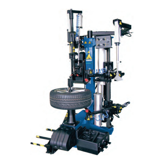
Spécifi cations Spezifi kationen 3.1 Accessoires 3.1 Zubehör Une série d’accessoires sont normalement disponibles Für die Maschine steht normalerweise eine Reihe von avec la machine. Zubehörteilen zur Verfügung. Tous les accessoires sont listés sur le site web : Eine Aufstellung der Zubehörteile fi nden Sie in der Website: http://service.snapon-equipment.net/ http://service.snapon-equipment.net/ Une fois entré... - Page 28 Specifi cations 4.0 Layout Refer to Figures 4.0-1 & 1.3-1. Functional description of the unit: 1. Vertical slide 2. Tool holder arm 3. Tool vertical slide control 4. Handle 5. Automatic Tool (or Head) 6. Tower (or column) 7. Wheel clamping fl ange (Self-centring table) 8.
-
Page 29: Description
Spécifi cations Spezifi kationen 4.0 Description 4.0 Identifi kation der einzelnen Teile Se reporter à la Figure 4.0-1 & 1.3-1. Description fonctionnelle de l’unité : Siehe Abbildung 4.0-1 & 1.3-1. Funktionsbeschreibung des Geräts: 1. Tige verticale 2. Bras porte-outil 1. Montierstange 3. - Page 30 Specifi cations 4.1 Controls Before operating the machine ensure that you have properly understood the operation and function of all the controls, as set out in this chapter. 4.0-1 Mount/demount tool position The push button on the handle (3, Fig.4.0-1) allows the user to position the tool correctly.
-
Page 31: Commandes
Spécifi cations Spezifi kationen 4.1 Commandes 4.1 Maschinenbedienung Avant de travailler avec la machine, s’assurer Vor Inbetriebnahme der Reifenmontiermaschine d’avoir bien compris la position et les fonctions des sollten Sie sich mit der Lage und Funktionsweise aller commandes , comme il est décrit dans ce chapitre. Steuerteile vertraut machen, wie sie in diesem Kapitel erklärt sind. - Page 32 Specifi cations Turntable rotation Press the pedal (4, Fig.4.1-4) WITH THE RIGHT FOOT; the wheel-holder fl ange rotates clockwise as follows. speed: About 3/4 of the way down, the turntable rotates at the minimum speed (about 7 rpm). speed: All the way down, the turntable rotates at maximum speed (about 14 rpm).
- Page 33 Spécifi cations Spezifi kationen Rotation plateau Drehen des Tisches Appuyer, AVEC LE PIED DROIT, sur la pédale (4, Mit dem RECHTEN FUSS das Pedal (4, Fig.4.1-4) Fig.4.1-4) ; la flasque porte-roue tourne en sens drücken – der Radhalterfl ansch dreht sich auf folgende horaire de la façon suivante.
- Page 34 Specifi cations - Control (1) released; the upper disc returns to its normal position. - Control (2) up; the lower disc tilts. - Control (2) released; the lower disc returns to its normal position. To lock the movement of both bead breaker arms, act on the manual control (5, Fig.4.1-5).
- Page 35 Spécifi cations Spezifi kationen s’incline. Änderung des Betriebswinkels der Reifenheber- - Commande (1) vers le haut ; le disque supérieur Scheiben aus, wodurch deren Eindringen in den Sitz retourne en position de base. der Wulste erleichtert wird. - Commande (2) vers le haut ; le disque inférieur - Steuerung (1) nach unten;...
- Page 36 Specifi cations (if present) Bead pusher The bead pusher tool (1, Fig.4.1-9) fitted on the articulated arm has a pneumatic control (2, Fig.4.1-9) for vertical movement. Lever up; the bead pusher moves up. Lever down; the bead pusher moves down WA R N IN G: TH E OP E RAT ION S C OU L D B E DANGEROUS.
- Page 37 Spécifi cations Spezifi kationen (si présent) (falls vorhanden) Presse-talon Wulstniederhalter L’outil presse-talon (1, Fig.4.1-9), monté sur le bras Der Wulstniederhalter (1, Abb.4.1-9), der am articulé, présente une commande pneumatique (2, Gelenkarm montiert ist, verfügt über eine pneumatische Fig.4.1-9) pour le mouvement vertical. Steuerung (2, Abb.4.1-9) für die Vertikalbewegung.
- Page 38 Operations 5.0 Operations - General precautions CAUTION: BEFORE MOUNTING A TIRE ON A RIM ENSURE THE FOLLOWING RULES ARE OBSERVED: A- THE RIM MUST BE CLEAN AND IN GOOD CONDITION: IF NECESSARY CLEAN AFTER REMOVING ALL WHEEL-WEIGHTS INCLUDING ‘TAPE WEIGHTS’ INSIDE THE RIM. B- THE TIRE MUST BE CLEAN AND DRY, WITH NO DAMAGE TO THE BEAD AND THE CASING.
-
Page 39: Opérativité - Précautions Générales
Opérativité Betrieb 5.0 Opérativité 5.0 Vorsichtsmassnahmen bei Betrieb - précautions générales ACHTUNG: ATTENTION: VOR DER REIFENMONTAGE FOLGENDE AVANT DE MONTER UN PNEU SUR UNE JANTE VORSICHTMASSREGELN BEACHTEN: SUIVRE LES INDICATIONS SUIVANTES: A- DIE FELGE MUSS SAUBER UND IN A- LA JANTE DOIT ÊTRE PROPRE ET EN BON ETAT: GUTEM ZUSTAND SEIN: FALLS NÖTIG, SI NÉCESSAIRE, LA NETTOYER APRÈS AVOIR D I E F E L G E R E I N I G E N , N A C H D E M... - Page 40 Operations Locking rims 70 kg MAX. 5.1.1 Using the Wheel Lifter (if present) WARNING: IF THE WHEELS ARE HEAVY USE THE LIFT DEVICE ON THE LEFT SIDE OF THE MACHINE Should the user require it, the machine is provided with 5.1-1 a lift device that will raise the wheel or bare rim from the ground to a height suitable for attachment.
-
Page 41: Blocage De La Jante
Opérativité Betrieb Blocage jante Aufspannung der Felgen 5.1.1 Utiliser l’élévateur (si présent) 5.1.1 Gebrauch der Hebevorrichtung (falls vorhanden) ATTENTION: DANS LE CAS DE ROUES LOURDES, UTILISER L’ELEVATEUR PREVU A CET EFFET ACHTUNG:BEI SCHWEREN RÄDERN MUSS DER SITUE SUR LE COTE GAUCHE DE LA MACHINE HEBER VERWENDET WERDEN, DER SICH AUF DER LINKEN SEITE DER MASCHINE BEFINDET. - Page 42 Operations 5.1.2 Locking Figure 5.1-3 • Rotate the rim on the fl ange of the tyre lever, until the drag device 1 is brought inside one of the concentric holes of the rim. • Place, on the Quick-Clamping Hub Nut with Pin clamping device 2, the suitable cone for the rim in use.
-
Page 43: Blocage
Opérativité Betrieb 5.1.2 Blocage 5.1.2 Aufspannen Figure 5.1-3 Abbildung 5.1-3 • Tourner la jante sur la Flasque du démonte-pneu • Die Felge am Flansch der Reifenmontiermaschine pour amener l’entraîneur 1 à l’intérieur d’un des drehen, bis die Mitnehmervorrichtung 1 in eines der orifi... - Page 44 Operations 5.2 Demounting tires Figure 5.2-1 • Remove all wheel-weights from the rim. Remove the valve stem or core and defl ate the tire. 5.2.1 Bead Breaking Upper Bead Breaking 5.2-1 First of all the Bead Breaker Disc must be placed in the correct position.
-
Page 45: Démontage Des Pneus
Opérativité Betrieb 5.2 Démontage pneus 5.2 Demontage von Reifen Abbildung 5.2-1 Figura 5.2-1 • Enlever toutes les masses des bords de la jante. • Alle Ausgleichsgewichte vom Felgenhorn entfernen. Enlever la valve et dégonfl er le pneu. Das Ventil herausnehmen und die Luft aus dem Reifen ablassen. - Page 46 Operations • From the disc on tire contact position, activate the lever 1 downwards. • Hold the control down for the entire time in which you wish to vary the angle. Lower bead breaking To break the second bead, it may be necessary to free the work area of the Upper Bead Breaker Arm;...
- Page 47 Opérativité Betrieb a ou non des diffi cultés à pénétrer; de cette position, • In der Position, in der die Scheibe auf den Reifen il pourra procéder à la modifi cation de l’angle de drückt, den Hebel 1 nach unten drücken. pénétration.
- Page 48 Operations 5.2.2 Removing the tires B E F O R E P R O C E E D I N G W I T H T H E T Y R E EXTRACTION, CHECK THAT BOTH BEADS ARE COMPLETELY BROKEN. 5.2.2.1 Head Positioning Procedure: •...
-
Page 49: Démontage Pneus
Opérativité Betrieb 5.2.2 Démontage Pneus 5.2.2 Demontage von Reifen BEVOR SIE DEN REIFEN ABZIEHEN, STELLEN SIE AVANT DE PROCER A L’EXTRACTION DU SICHER, DASS BEIDE WÜLSTE VOLLSTÄNDIG PNEU VERIFIER SI LES DEUX TALONS SONT COMPLETEMENT DEJANTES. ABGEDRÜCKT SIND. 5.2.2.1 Positionierung des Werkzeugs 5.2.2.1 Positionnement Outil Procédure: Vorgehen:... - Page 50 Operations • Raise the tool claw once again, lubricate the side of the tyre and then press the tyre shoulder with the shoulder press arm to create suffi cient space to insert the claw. • Lower the Tool Claw once again, checking its correct introduction between the rim and tyre.
-
Page 51: Extraire Le Talon Inférieur
Opérativité Betrieb • Soulever à nouveau la pointe de l'outil, lubrifi er le • Die Werkzeugspitze erneut anheben, den Reifen fl anc du pneu puis exercer une pression avec le seitlich schmieren und anschließend mit dem bras presseur sur l'épaulement de celui-ci, pour créer Schulterniederhalterarm auf den Reifen drücken, l'espace nécessaire à... - Page 52 Operations Note: For this positioning you can use the bead breaker (Figure 5.2-13). • Use the demounting tool control lever to lift the bead out of the rim edge • Rotate the turntable until the tyre is completely removed. 5.2.3 Using the Bead Pusher and Bead 5.2-13 Breaker Disc during demounting To aid demounting of wheels with particularly rigid or...
-
Page 53: Presse-Talon Et Disque Lors Du Démontage
Opérativité Betrieb Nota bene: Ce positionnement peut être facilité si on Anm.: Bei dieser Positionierung kann man sich recourt à un outil de déjantage (Fig.5.2-13). mit dem Abdrückarm helfen (Abb. 5.2- 13). • Agir sur la commande de l'outil de démontage, pour soulever le talon hors du bord de la jante. - Page 54 Operations 5.3 Mounting tires Note: If mounting a tire starting from the bare rim, clamp in place as described in section 5.1 Locking Rims. Figure 5.3-1 • Lubricate the entire rim surface. 5.3-1 Figure 5.3-2 • Lubricate both beads of the tire, inside and outside, with a tire lubricant.
-
Page 55: Montage Des Pneus
Opérativité Betrieb 5.3 Montage pneus 5.3 Reifenmontage Remarque: Dans le cas d’un montage d’un pneu à Anm.: Wenn man einen Reifen ausgehend von einer bloßen Felge montieren muss, partir d’une jante nue, effectuer la fi xation comme il est décrit rubrique 5.1 Blocage erfolgt die Befestigung so, wie im Kapitel jante. - Page 56 Operations 5.3.1 Using the Bead Pusher and Bead Breaker Disc during mounting During the mounting tasks the operator can make use of the Bead Pusher tool and the Bead Breaker Disc, so as to limit manual work. Example of use of above-cited elements for certain tasks.
-
Page 57: Presse-Talon Et Disque Lors Du Montage
Opérativité Betrieb 5.3.1 Einsatz des Wulstniederhalters und der Wulstablösscheibe bei der Reifenmontage 5.3.1 Emploi du presse-talon et du disque de déjantage en phase de montage Auch beim Montieren kann der Bediener den Wulstniederhalter und die Wulstablösscheibe anwenden und dadurch seine eigene manuelle Arbeit vereinfachen. Pendant les opérations de montage, l’opérateur peut recourir au presse-talon et au disque de déjantage et Hier ein Beispiel für die Anwendung der oben... - Page 58 Operations 5.4 WDK PROCEDURE Only for Gold and Platinum versions For these tire changer versions no additional kits or components are required to perform WDK tire mount- ing/demounting procedures correctly. The operating procedures described in this manual comply with “WDK” tire mounting/demounting proce- dure specifi...
-
Page 59: Procédures Wdk
Opérativité Betrieb 5.4 PROCÉDURE WDK 5.4 WDK-VORGEHEN Uniquement pour les versions Gold et Platinum Nur für die Versionen Gold und Platinum Pour ces versions de démonte-pneus, les procédures Bei diesen Versionen der Reifenmontiergeräte können WDK de montage/démontage peuvent être exécutées die „wdk“-Vorgehen zum Montieren bzw. - Page 60 Operations Insert the plastic lever supplied between the edge of the rim and the internal part of the upper bead as shown in (Figura 5.4.2). Rotate the wheel until the upper side of the tire is completely demounted. Complete the demounting phase as described in the instructions for conventional wheels.
-
Page 61: Montage Des Pneus
Opérativité Betrieb ACHTUNG: Diese Tätigkeit muss durchgeführt Introduire le levier en plastique fourni entre le bord werden, OHNE das Rad zu drehen. de la jante et la partie intérieure du talon supérieur (Figura 5.4.2). Stecken Sie den Kunststoffhebel zwischen den Rand der Felge und die Innenseite des oberen Wulstes Mettre la roue en rotation, jusqu’au retrait complet de (Abbildung 5.4.2). - Page 62 Operations which have a very sharp edge, you will also need to use the plastic protection shown in Figure 5.4.6. This must be placed over the rim and locked in position by the manual bead pusher to avoid damaging the bead during the fi...
- Page 63 Opérativité Betrieb en alliage qui présentent une arête particulièrement Bei Stahlfelgen und auch bei einigen Leichtmetallfel- tranchante, la protection en plastique illustrée en Fig- gen, die einen besonders scharfen Rand haben, muss ure 5.4.6 devra aussi être utilisée. auch der in der Abbildung 5.4.6 gezeigte Kunststoff- schutz verwendet werden.
- Page 64 Operations 5.5 Beading the tires Beading means the initial grip of the tire bead on the rim, in order to allow the infl ation operations and subsequent settling in the seat on the rim. Safety Precautions: WARNING: DO NOT USE THE TIRE CHANGER TO INFLATE TIRES.
-
Page 65: Enjantage Talon
Opérativité Betrieb 5.5 Enjantage du talon des pneus 5.5 Eindrücken der Reifenwülste Par enjantage du talon, on entend l’adhérence intiale Unter Wulsteindrücken wird verstanden, dass man du talon du pneu à la jante, de manière à permettre la die Reifenwülste anfänglich so an der Felge anlegt, suite des opérations à... - Page 66 Operations • Screw the valve insert. • Connect the compressed air hose to the valve (Figure 5.5-1 / 5.5-3). • Place the inner tube inside the tire. Using talcum powder may facilitate this operation. • Operate the compressed air to ensure the beads are seated.
- Page 67 Opérativité Betrieb • Visser l’insert valve. • Den Ventilaufsatz anschrauben. • Raccorder le tube de l’air comprimé à la valve • Den Druckluftschlauch an das Ventil anschließen (Figure 5.5-1 / 5.5-3). (Abbildung 5.5-1 / 5.5-3). • Bien répartir la chambre à air dans le pneu. L’emploi •...
- Page 68 Disposal 6.0 Maintenance This tire demount unit will continue to provide maximum working effi ciency even after a long period of intensive use as long as the operator carries out scheduled maintenance as indicated below. BEFORE ATTEMPING ANY MAINTENANCE OR REPAIRS THE MACHINE MUST BE DISCONNECTED FROM THE ELECTRICAL POWER SUPPLY AND THE COMPRESSED AIR FEED LINE.
-
Page 69: Entretien
Vente De La Machine Entsorgung 6.0 Entretien 6.0 Wartung Un entretien périodique permet à l’opérateur de tirer Diese Reifenmontiermaschine kann auch bei langer un maximum de profi t de ce démonte-pneu et de le und intensiver Arbeit höchste Effi zienz gewährleisten, conserver en bon état, y compris en cas d’usage intensif. - Page 70 Disposal 3) Pneumatic cylinder rods Figure 6.0-4 • Check that the lubrication unit is working properly. One oil drop falling into the transparent cone G every 4-5 complete strokes of the bead breaker indicates that the correct amount of oil is being dispersed in the system. If necessary, •...
- Page 71 Vente De La Machine Entsorgung 3) Tiges des vérins pneumatiques 2) Vertikaler Gleitzylinder des Werkzeugs 3) Stangen der Pneumatikzylinder Figure 6.0-4 • Contrôler le fonctionnement du graisseur. Abbildung 6.0-4 Une goutte qui tombe dans le dôme transparent • Die Funktionstüchtigkeit des Luftölers überprüfen. ‘G’...
- Page 72 Disposal CALIBRATING THE LASER Clamp a 17” rim on the machine self-centring chuck. Fit a rim protector for fun fl at wheels (supplied with the machine (1 Fig. 6.0-5). WARNING: THE RIM PROTECTOR MUST BE IN PERFECT CONDITION. USING WORN OR BROKEN PROTECTORS WILL COMPROMISE THE ACCURACY OF THE LASER CALIBRATION AND MAY RESULT IN DAMAGE TO THE RIM.
-
Page 73: Entreposage
Vente De La Machine Entsorgung CALIBRAGE DU LASER JUSTIERUNG DES LASERS Bloquer une roue de 17» sur l’autocentrant de la Befestigen Sie eine Felge zu 17“ an der machine . Spannvorrichtung der Maschine. Installer sur le bord de la roue un protecteur roue Installieren Sie am Felgenrand einen Felgenschutz pour roues run fl... - Page 74 Disposal 7.0 Troubleshooting If a problem with the tire changer should arise, proceed in the following order to solve the problem: 1. Rethink the last steps taken. Did you work according to the manual? Did the unit work as described and expected? 2.
-
Page 75: Dépannage
Vente De La Machine Entsorgung 7.0 Dépannage 7.0 Fehlerbeseitigung En cas de problème avec le démonte-pneu, procéder Sollte ein Problem mit der Reifenmontiermaschine comme suit pour résoudre le problème: auftreten, gehen Sie bitte in der nachfolgend beschriebenen Reihenfolge vor, um es zu lösen: 1. - Page 76 Disposal Machine damages alloy rims. 1. Plastic tool guard worn. • Replace the plastic tool guard. 2. Tool is at wrong distance from rim. • Call the authorized assistance service. Irregular movement of swing arm. Wheel lifter jammed. 1. Low air pressure. •...
- Page 77 Vente De La Machine Entsorgung La machine endommage les jantes en alliage. 1. Protection en plastique de l’outil usée. Leichtmetallfelgen werden beschädigt. 1. Plastikschutz am Montagewerkzeug abgenutzt. • Remplacer la protection en plastique de l’outil. • Plastikschutz am Montagewerkzeug auswechseln. 2.
- Page 78 Disposal 8.0 Disposing of the unit When you decide to get rid of your unit, contact your reseller for a quote or for the regulations on disposal which apply to the unit. 8.1 Instructions for disposal in EU countries For waste electrical and electronic equipment At the time of disposal, at the end of the lifetime of this equipment, you must: 1.
-
Page 79: Vente De La Machine
Vente De La Machine Entsorgung 8.0 Vente 8.0 Entsorgung Lorsque vous décidez de vendre la machine, contactez Wenn das Gerät entsorgt werden soll, setzen Sie votre revendeur pour obtenir le prix offert ou les sich bitte mit Ihrem Händler in Verbindung und fragen règlements appropriés pour la revente de la machine. - Page 81 Appendix: Installation Instructions. This appendix describes the installation requirements, procedures and checks. Annexe: Instructions pour l’Installation. Cette annexe traite des conditions requises, des procédures et des vérifi cations nécessaires pour l’installation. Anhang: Installationsanweisungen In diesem Anhang werden die Installationsanforderungen, der Installationsvorgang und die Überprüfungen beschrieben.
- Page 82 Installation Instructions i. Installation requirements. THE INSTALLATION SHALL BE CARRIED OUT ONLY BY QUALIFIED PERSONNEL AND WITHIN THE SCOPE OF THE INSTRUCTIONS PROVIDED IN THIS MANUAL. Install the machine in a covered and dry area. Fig.i-1 The installation of the machine requires a free space of at least 3x3 m (106”x106”).
-
Page 83: Installationsanforderungen
Instructions d’installation Installationsanweisungen i . C o n d i t i o n s r e q u i s e s p o u r i. Installationsanforderungen l’installation. DIE INSTALLATION IST VON FACHPERSONAL UNTER STRENGER EINHALTUNG DER HIER L’INSTALLATION DOIT ÊTRE EFFECTUÉE PAR AUFGEFÜHRTEN ANWEISUNGEN DURCH- UN PERSONNEL QUALIFIÉ... - Page 84 Installation Instructions i. Transport - Unpacking - Handling the machine Carriage instructions The machine is normally crated in a corrugated box of appropriate strength. The box is mounted on a pallet. Handling of the completely crated machine or simply placed on a pallet (b-Fig.ii-1), must be made with an appropriate lifting device (fork lift) (a - Fig.ii-1).
-
Page 85: Transport-Déballage-Manutention
Instructions d’installation Installationsanweisungen i. Transport - Déballage - Manutention i . Tr a n s p o r t - A u s p a c k e n - Innerbetriebliche Umsetzung der Transport Maschine La machine est normalement emballée dans une boîte en carton. - Page 86 Installation Instructions • Remove from the machine any accessories or parts that might fall during handing and so cause danger. Use lifting and handling, equipment with a carrying capacity no lower than 1000 Kg. Use polyester lifting slings, of a lifting capacity of at least 1000 kg, of a length of 1500 mm in the front positions (1 and 2) and a length of 500 mm on the rear (3).
- Page 87 Instructions d’installation Installationsanweisungen Utiliser des équipements de levage et manutention des Transports herunterfallen und dadurch Gefahren d’une portée non inférieure à 1000 Kg. hervorrufen könnten, von der Maschine ab. Entsprechende Ausrüstung zum Anheben und Befördern Utiliser des sangles de levage en polyester, d’une portée mit einer Tragfähigkeit von mindestens 1000 kg verwenden.
- Page 88 Installation Instructions 6.3.4 INSTALLATION DEVICE The device, designed to remove large tyre changers from pallets and place them on the ground, is available on request and must be used exclusively by authorised installers and with the relevant machine models. Scope of application: The list of machine models that the equipment can be used with can be found in instruction TEAK0330G24A supplied with the device.
-
Page 89: Ii.1 Dispositif D'installation
Instructions d’installation Installationsanweisungen 6.3.4 DISPOSITIF D’INSTALLATION 6.3.4 INSTALLATIONSVORRICHTUNG Le dispositif, spécialement conçu pour enlever de la Die Vorrichtung, die speziell entwickelt wurde, palette et poser au sol des démonte-pneus de grandes Reifenmontiermaschinen mit beträchtlichen Abmessungen dimensions, peut être fourni sur demande et doit être von der Palette zu nehmen und auf dem Boden utilisé... - Page 90 Installation Instructions iii Installation procedures. Electrical connections THE INSTALLATION SHALL BE CARRIED OUT ONLY BY QUALIFIED PERSONNEL AND WITHIN THE SCOPE OF THE INSTRUCTIONS PROVIDED IN THIS MANUAL. WARNING: ENSURE THAT AN APPROVED WALL-MOUNTED MAINS OUTLET IS AVAILABLE. WARNING: NEVER LAY POWER SUPPLY CABLES OVER THE FLOOR, UNLESS PROTECTED BY AN APPROVED COVER.
-
Page 91: Procédures D'installation
Instructions d’installation Installationsanweisungen iii Procédures d’installation. iii Installationsvorgang Branchement électrique Elektrischer Anschluss DIE INSTALLATION IST VON FACHPERSONAL L’INSTA LLATION DOIT ÊTRE EFFECTUÉE UNTER STRENGER EINHALTUNG DER HIER EXCLUSIVEMENT PAR UN PERSONNEL QUALIFIÉ, DANS LE TOTAL RESPECT DES AUFGEFÜHRTEN ANWEISUNGEN DURCH- INSTRUCTIONS FIGURANT DANS CE MANUEL. - Page 92 Installation Instructions Pneumatic connection PNEUMATIC INSTALLATION MUST BE PERFORMED ONLY BY LICENSED PERSONNEL. The machine requires an air pressure of 8 to 10 bar (116-145 psi), as marked on the plate of the machine and on a sticker attached to the cabinet next to the air inlet.
-
Page 93: Branchement Pneumatique
Instructions d’installation Installationsanweisungen Branchement pneumatique Druckluftanschluss L’INSTALLATION PNEUMATIQUE DOIT ÊTRE DER DRUCKLUFTANSCHLUSS DARF NUR VON EFFECTUÉE PAR UN PERSONNEL SPECIALISE. EINER FACHKRAFT VORGENOMMEN WERDEN. La machine, comme l’indique la plaquette du Die Maschine ist für einen Pneumatikversorgung mit constructeur et l’étiquette apposée à proximité du einem Druck von 8 bis 10 bar ausgelegt, wie es auch branchement de l’air, fonctionne avec une alimentation auf dem Maschinenschild und auf dem in der Nähe des... - Page 94 Installation Instructions IV. Testing procedures Motor rotation check This type of check must be made on machines at the end of installation only. • Press the turntable rotation control pedal: the wheel must start and turn clockwise. Should it rotate anticlockwise the machine must be stopped and must not be used until it has been repaired by an authorized technician.
-
Page 95: Procédures De Test
Instructions d’installation Installationsanweisungen IV. Procédures de test IV. Testverfahren Contrôle du sens de rotation du moteur Kontrolle der Drehrichtung des Motors Ce contrôle doit être effectué à la fi n de la première Diese Überprüfung muss am Ende der Erstinstallation installation. - Page 96 Notice: The information contained in this document is subject to change without notice. Hofmann makes no warranty with regard to present documentation. Hofmann shall not be liable for errors contained here- in or for incidental consequential damages in connection with furnishings, performance, or use of this material. ·...
Need help?
Do you have a question about the monty 8600 Series and is the answer not in the manual?
Questions and answers