Table of Contents
Advertisement
Quick Links
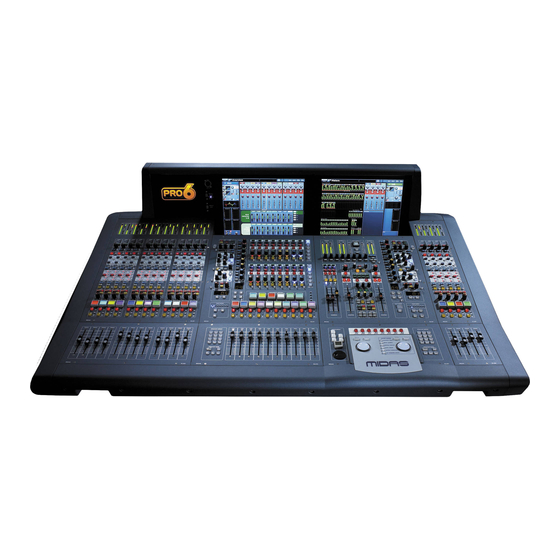
PRO6 Live Audio System
Owner's Manual
Midas Klark Teknik Limited,
Klark Industrial Park,
Walter Nash Road,
Kidderminster.
Worcestershire.
DY11 7HJ.
England.
Tel: +44 1562 741515
Fax: +44 1562 745371
Email: info@midasklarkteknik.com
Website: www.midasconsoles.com
PRO6 Live Audio System — Owner's Manual
DOC02-DL3 Issue C — June 2010
© Red Chip Company Ltd.
In line with the company's policy of continual improvement, specifications and function may be
subject to change without notice. This Operator Manual was correct at the time of writing. E&OE.
Advertisement
Table of Contents
Troubleshooting

Subscribe to Our Youtube Channel
Related Manuals for Midas PRO6


Summary of Contents for Midas PRO6
- Page 1 Fax: +44 1562 745371 Email: info@midasklarkteknik.com Website: www.midasconsoles.com PRO6 Live Audio System — Owner’s Manual DOC02-DL3 Issue C — June 2010 © Red Chip Company Ltd. In line with the company’s policy of continual improvement, specifications and function may be...
-
Page 3: Important Safety Instructions
IMPORTANT SAFETY INSTRUCTIONS The lightning flash with arrowhead symbol within an equilateral triangle is intended to alert the user to the presence of uninsulated “dangerous voltage” within the product's enclosure that may be of sufficient magnitude to constitute a risk of electric shock to persons. The exclamation point within an equilateral triangle is intended to alert the user to the presence of important operating and maintenance (servicing) instructions in the literature accompanying the product. -
Page 5: Ec-Declaration Of Conformity
EC-Declaration of Conformity Midas EC-Declaration of Conformity The undersigned, representing the following manufacturer Manufacturer: Address: Midas Klark Teknik Ltd. Klark Industrial Park, Walter Nash Road, Kidderminster. Worcestershire. DY11 7HJ. hereby declares that the following product Product Type Number Product Description... -
Page 7: Licences
Midas™ or Klark Teknik™ Product, as well as other software that we provide for installation on this Product. The Midas™ or Klark Teknik™ Product will not operate in accordance with its documentation without this software. - Page 8 If you wish to receive a computer-readable copy of the source code for any of the GNU Linux Programs that have been provided with your Midas™ or Klark Teknik™ Product, send a cheque or money order (no cash accepted), your address and [£10.00] to cover the cost...
- Page 9 GNU General Public License (GPL) For details of the Third Party Software License Attribution, Copyright and Terms and Conditions and Notices, and the GNU LESSER GENERAL PUBLIC LICENSE, see the Midas Digital Equipment GNU General Public License (GPL) Booklet part number DOC04-GPL issue A.
-
Page 11: Precautions
The system power supplies contain LETHAL power off first. VOLTAGES greatly in excess of the mains Before switching the PRO6 Control Centre on or voltage and its rails can produce extremely large off, make sure that all monitor loudspeaker currents that could burn out equipment and power amplifiers are turned off or muted. - Page 12 Do not install this equipment in a location the equipment is operated in a commercial subjected to excessive heat, dust or mechanical environment. This equipment generates, uses, vibration. Allow for adequate ventilation around and can radiate radio frequency energy and, if PRO6 Live Audio System Owner’s Manual...
- Page 13 Degradation of up to 60dB at a this equipment; do not use any alternatives as frequency corresponding to the modulation they may not fulfil the RF requirement. signal may be experienced under extreme conditions (3V/m, 90% modulation). PRO6 Live Audio System Owner’s Manual...
- Page 14 Precautions PRO6 Live Audio System Owner’s Manual...
-
Page 15: Table Of Contents
Training ..........3 PRO6 user documentation ....... . . 3 PRO6 host software version . - Page 16 Bay and GUI layout ........18 PRO6 control surface ........19 GUI .
- Page 17 Introduction ......... . 55 Terms used in PRO6 patching ......55 About the Patching screen .
- Page 18 Controlling a GEQ via the I zone ......174 PRO6 Live Audio System Owner’s Manual...
- Page 19 About the Files screen ........217 About the Master Controller File Synchronisation window ..219 PRO6 Live Audio System Owner’s Manual...
- Page 20 Configuring a virtual soundcheck ......226 Restoring the PRO6 defaults ......226 Checking the PRO6 build information .
- Page 21 PRO6 main processing functions ......333 PRO6 status functions ........336 Appendix C Klark Teknik DN370 GEQ .
- Page 22 About the updater screen ....... .368 Using the PRO6 updater ....... . .370 Appendix I Documentation .
- Page 23 ......... 579 PRO6 Live Audio System...
- Page 24 Contents PRO6 Live Audio System Owner’s Manual...
- Page 25 Overview Volume 1: PRO6 Live Audio System Owner’s Manual...
-
Page 27: Introduction
• Overview: This gives an overview of the PRO6 Live Audio System and PRO6 Control Centre and contains information about this manual. • Getting Started: This shows you how to set up and power up a PRO6 system. • Basic Operation Of The PRO6: This shows you how to use the controls of the... - Page 28 To support both FOH and MON use, the terminology has been chosen very carefully to apply equally to both (see "Glossary" on page 579). For a definition of the PRO6’s primary buses, see “Definition of the primary buses” on page 375.
-
Page 29: Training
Anti-aliasing To make the GUI of the PRO6 as crisp, eye-catching and as intelligible as possible it incorporates an anti-aliasing algorithm to ensure the utmost smoothness of straight lines and curves. Unfortunately, this quality is not truly reflected in this manual. - Page 30 Chapter 1: Introduction PRO6 Live Audio System Owner’s Manual...
-
Page 31: Pro6 Live Audio System
1,000 scenes with snapshot save/recall capability and global edit, and show file archiving. The PRO6 Control Centre forms the core of the PRO6 Live Audio System, which also includes two 19” rack units — a DL351 Modular I/O (7U) and a DL371 Audio System Engine (7U) —... -
Page 32: Key Features
Chapter 2: PRO6 Live Audio System Key features Please remember, the PRO6 is not just a console, it’s a LIVE AUDIO SYSTEM! • High channel count — 56 mixed primary inputs (sourced from up to 112 input locations) and 35 output channels. -
Page 33: Applications
• Modular digital and analogue I/O options. • Advanced automation and system operating preferences. • PRO6 is flexible and the system can be customised with the needs of the install. • VGA outputs for additional screens. • Reliability — High reliability with some redundancy and other back up contingencies. -
Page 34: System Components (Standard Supply)
HyperMac Cat 5e copper cables, each 100 m long. • 8-off mains cables. FOH and MON The PRO6 Live Audio System can be used as a front of house (FOH) or stage monitor (MON) system. System buses The PRO6 has comprehensive system buses to suit demanding applications, comprising: •... -
Page 35: Mix Matrix
Mix matrix Ultimately, the mix matrix defines the capability of the PRO6 Control Centre. Probably the best way to imagine the mix matrix is to think of an analogue console layout, where inputs run vertically and buses run horizontally. -
Page 36: Processing
Chapter 2: PRO6 Live Audio System Processing Although the control centre system allows for considerable insertion of external processing it also embodies more than enough internal high quality processing to eliminate the need for this, in the interests of simplicity and reduced overall system size, weight and cost. - Page 37 • Direct input. Each of the three master output buses has: • Six-band PEQ. • Optional 31-band GEQ (replaces PEQ). • Five-mode frequency-conscious compressor with soft clip limiter and external side chain. • Insert point. PRO6 Live Audio System Owner’s Manual...
-
Page 38: Audio Physical Connections
(STS™)) on the PRO6 Control Centre or by buttons on the RapidE itself. Audio physical connections The total number of audio connections, that is, the XLR count, for a standard PRO6 Live Audio System is 96. This includes dedicated and configurable XLR connections. The dedicated XLR connections on the DL351 Modular I/O comprises 56-off mic/line inputs. -
Page 39: Surround Capabilities
• 5.1 Surround Left – Right – Centre – Sub – LS – RS routing to Matrix 1, 2, 3, 4, 5 and 6. Network The MidasNET network of the PRO6 utilises the physical connectivity of Ethernet (EtherCon® connectors and Cat 5e/copper cable), but replaces its data protocol with AES50 protocol (implemented as SuperMac) and the HyperMac high capacity system, which are more suited to high quality, low latency audio distribution. -
Page 40: Control Software
Additional digital I/O format options will be available later, for example, MADI. Console linking You can link two PRO6 Control Centres together. Just connect an AES50 cable from a spare AES50 port on one router to a spare port on another, and then set them up “Generic AES50”... - Page 41 PC or MAC computers can use the Ethernet tunnel in the MidasNET system, and can communicate with other computers on the network. The PRO6 Control Centre features an external video for both screens, and the master bay GUI screen (on the right) also has a three-way KVM switch. Control centre views can be routed to external monitors, and external video sources can be displayed on the control centre.
- Page 42 Chapter 2: PRO6 Live Audio System PRO6 Live Audio System Owner’s Manual...
-
Page 43: About The Pro6 Control Centre
The PRO6 Control Centre has a combined control surface and GUI that provide an array of easy-to-use controls for the precise manipulation of audio. The PRO6 Control Centre is of modular construction and is built on a robust Midas steel frame chassis similar to those used for established Midas analogue products. The frame houses three full size bays with a smaller one on the right. -
Page 44: Bay And Gui Layout
This is further helped by the modular nature of the bays and GUI independence. Either of the GUI screens can be used to operate the whole PRO6 Control Centre, even if none of the control surface hardware is working. The unit offers the facility of universal input, N+1 redundant power supplies with three latching mains connectors. -
Page 45: Pro6 Control Surface
PRO6 control surface PRO6 control surface The control surface of the PRO6 Control Centre is divided into areas (see Figure 2) whose function is, largely, dependent on bay location. Each bay has assorted control elements with local feedback and/or support from the two centrally located GUI display screens. -
Page 46: Gui
GUI menu. This menu provides access to all the screens that you will require to set up, configure, manage and operate the entire PRO6 Control Centre, all from a single drop-down list of easy to follow options. -
Page 47: Front And Rear Panel Connections
A section and the other one is for monitor B. A connector panel on the rear of the PRO6 Control Centre has three main sections (see below). On the left are three mains power inlet and ventilation assemblies, with a DC power switch above. -
Page 48: External Interfaces And Peripheral Devices
GUI screens, you can use an external USB mouse. This can be plugged into any of the USB connectors on the PRO6. The USB mouse behaves in the same way as any PC mouse. For more information, see “Using an external USB mouse” on page 323. -
Page 49: Automation
The ‘next’ LCD button has been positioned close to the VCA faders and has been purposely designed so as to be distinct from other functions. Processing elements For details of the processing elements of the PRO6, see “Processing” on page 10 and “PRO6 main processing functions” on page 333. PRO6 Live Audio System... - Page 50 Chapter 3: About The PRO6 Control Centre PRO6 Live Audio System Owner’s Manual...
- Page 51 Getting Started Volume 1: PRO6 Live Audio System Owner’s Manual...
-
Page 53: Setting Up The System
Chapter 4: Setting Up The System This chapter shows you how to set up a PRO6 Live Audio System to its default configuration. Note: If you want to set up the PRO6 Live Audio System using a configuration other than the default, please contact Midas Technical Support for details. -
Page 54: Wiring Instructions
Midas units. To avoid this, we recommend that any non-Midas units are housed separately. • Rack mount supports: Always secure the rear of the PRO6 units to the rack via their rear rack mount support brackets. These brackets are fitted to every PRO6 unit and are recommended for use in touring applications. - Page 55 Figure 4: Standard system configuration Important: The PRO6 Control Centre, DL351 Modular I/O and DL371 Audio System Engine all have Volex locking type plugs fitted on their supplied mains cables, which plug into their mains IEC connectors. When fitted properly the Volex plug locks into place, preventing it working loose, or being inadvertently knocked loose or pulled out.
-
Page 56: Powering The Pro6 System
After all PRO6 system interconnections have been made (refer to Figure 4 “Standard system configuration” on page 29), start up the PRO6 system: Make sure that all of the PRO6 system equipment is switched off, such as the PRO6 Control Centre, speaker sub-system, DL351 Modular I/O unit and DL371 Audio System Engine unit. -
Page 57: Switching The Pro6 Control Centre On/Off
Switching the PRO6 Control Centre on/off Switching the PRO6 Control Centre on/off Carry out the following to switch the PRO6 Control Centre on or off in a safe manner, observing all WARNINGS and Cautions. >> To switch on the PRO6 Control Centre... -
Page 58: Setting Up The Dl351 Modular I/O Unit Id
ID of the unit shown in Figure 5 is “1”. To change the ID number there is no need to switch on the PRO6 Control Centre, as the procedure can be carried out offline. - Page 59 Basic Operation Volume 2: Of The PRO6 PRO6 Live Audio System Owner’s Manual...
-
Page 61: Before You Start
Chapter 5: Before You Start This chapter is intended to familiarise you with the PRO6 Control Centre by showing you how to carry out some basic operations in order to get some audio out of it. Note: As the operation of both input bays is principally the same, this chapter will generally only show the operation of the 12-channel input bay. -
Page 62: Hints And Tips
“MONO AUX”. Hints and tips • Check what is hidden: On the PRO6, unlike on an analogue control surface, some of the settings and parameters will be hidden from view (stored in the computer memory of the PRO6). At various times during a mix we recommend that you select and view unused parameters to make sure there are no hidden surprises, for example, a reverb send left from a previous mix. -
Page 63: Saving Your Work
• Saving a show copies the show file onto the internal solid-state disk of the PRO6. This provides you with a ‘permanent’ copy, provided you shut down the system properly as detailed in the following section. - Page 64 Chapter 5: Before You Start PRO6 Live Audio System Owner’s Manual...
-
Page 65: Working With The Pro6 Control Centre
This chapter is intended to familiarise you with controls (control surface and GUI) of the PRO6 Control Centre. Although nearly all of the operations are done via the control surface of the PRO6 Control Centre can be replicated via the GUI, the emphasis in this chapter — and throughout the manual —... -
Page 66: About Channel Operation
The ‘all meters’ display of the master bay’s default GUI screen (see Figure 20, “Layout of the GUI screens,” on page 116) provides an overview of what is happening in the PRO6 by displaying meters for all of the channels (inputs, outputs, monitors etc.). About channel operation During normal operation the task of controlling the input (12 channels), aux, return and matrix channels is allocated to the two bays on the left. - Page 67 (see “To select a block of patch connectors in the From section” on page 75). The pointer disappears when the control has been selected to show that it is ready for adjustment. PRO6 Live Audio System Owner’s Manual...
-
Page 68: Common Gui Screen Elements
User library buttons (see “User library (presets)” on page 99). Parameter values displayed on touch You can configure the PRO6 (see “Changing the user interface preferences” on page 228) so that the GUI displays the current value (and dimension) of the control being adjusted. - Page 69 OK and a CANCEL button by which you can acknowledge the message or cancel the operation, respectively. Also, some message Properties windows contain a user-editable text window List window field, as shown in the example (right). PRO6 Live Audio System Owner’s Manual...
-
Page 70: Using The Gui Menu
Chapter 6: Working With The PRO6 Control Centre • List windows have a number of user-selectable options in the form of a list, and some may also include an OK and a CANCEL button. Similar to a window found on a PC running a Windows-based operating system, windows can be moved around the screen, which is useful if you need to see what is behind the window. -
Page 71: Text Editing
Using the keyboard, type in the new text. If the text box already contains some text, you can delete this first or edit it, which can be done via the keyboard or by using the cut, copy and paste options after right-clicking. PRO6 Live Audio System Owner’s Manual... - Page 72 Chapter 6: Working With The PRO6 Control Centre Press ENTER on the keyboard to exit the text box (or click on an empty area of the GUI screen). The pointer’s shape will change back to an arrow. PRO6 Live Audio System...
-
Page 73: Navigation
‘hidden’. So, navigation is required to access these hidden channels whenever you need them. The way the PRO6 is set to operate may alter the function of some of the navigational controls. For more information, see “Operating modes” on page 35. -
Page 74: About The Navigational Controls
Figure 8: Input channels in the input bays About the navigational controls The PRO6 navigational controls can be broadly divided into two main areas: those that operate the channels currently populating the control surface (quick access buttons and LCD select buttons) and the ones that navigate channels to/from the control surface (scroll buttons and output select buttons) —... -
Page 75: About Gui Navigation
With a channel overview displayed in the GUI channel strip, click in a non-control area of the section you want. To access the mix bus processing area, click on the aux or matrix text in the overview display of the channel strip. PRO6 Live Audio System Owner’s Manual... -
Page 76: About The Navigation 'Select' Sections
(aux or matrix) of the currently select mix bus. The quick access button assigns the currently selected mix bus to the channel strip. • channel select (lower) and channel type sections — see Table 1 “Description of the navigational controls” on page 48. PRO6 Live Audio System Owner’s Manual... -
Page 77: How To Navigate
• Scroll to the mix bus using the scroll by 1 buttons in the mix section. This will also select the mix bus. • Scroll the bank containing the mix bus you require (aux or matrix) to the control surface using the scroll by 8 buttons in the sends section. PRO6 Live Audio System Owner’s Manual... - Page 78 Note: Items A to G are replicated on the far right side of the control surface, although the master bay’s input select section also has an area B button. Figure 9: Location of the navigational controls on the control surface PRO6 Live Audio System Owner’s Manual...
- Page 79 >> To navigate the selected mix bus to a channel strip Press the quick access button in the mix section. This does not affect the current population of the output fast zone. PRO6 Live Audio System Owner’s Manual...
- Page 80 For example, if the channel is an input, press INPUT. In the channel select (lower) section, type in the channel’s number. For example, press 4 and then 7 for channel 47. Press ENTER. PRO6 Live Audio System Owner’s Manual...
-
Page 81: Patching
Patching is a GUI-only feature that allows you to carry out all the routing requirements of the PRO6. The GUI main menu has a Patching option that takes you to the Patching screen, which contains all of the available patching connectors on the PRO6. - Page 82 • Press the patching/metering button in the primary navigation zone. • At the appropriate GUI screen, click the src (source) or dest (destination) button. The Patching screen will open at the appropriate tab/configuration window. PRO6 Live Audio System Owner’s Manual...
- Page 83 CONFIG Opens the AES50 Device Configuration window, from where you can set up the I/O tabs in the Patching screen (see “The AES50 Device Configuration window” on page 72). PRO6 Live Audio System Owner’s Manual...
- Page 84 Non-functional patch connector, that is, one that cannot be patched. Compressor sidechain input patch connector. Gate input patch connector. DN9696 recorder patch connector. Set-up button, which opens the device configuration window (see “Configuring the devices” on page 68 for details). PRO6 Live Audio System Owner’s Manual...
- Page 85 The Dir. Out (Direct Out) tab allows you to patch any of the 56 input channels internally to, for example, an effect, or to provide a way out of the PRO6 Control Centre via a line I/O unit. PRO6 Live Audio System...
- Page 86 The Effects tab allows patching from any of the internal effects. Each effect can support up to eight inputs and outputs, depending on which effects device is loaded. Stereo effects use the first two inputs/outputs. PRO6 Live Audio System Owner’s Manual...
- Page 87 Although this is the equivalent of the Stage I/O tab in the From section, this one does not contain any mic splitters, as they don’t supply any inputs to the PRO6 Control Centre. Refer to Figure >>, “To access the Patching screen,” on page 56 and “System components (standard supply)”...
- Page 88 A signal connected to a direct input can access the dynamics and EQ processing available on that output. This allows the aux bus masters to be used as additional input channels. PRO6 Live Audio System Owner’s Manual...
- Page 89 Ins. Ret. (Insert Return) tab. Effects tab The Effects tab allows patching to all of the effects. Refer to “Effects tab” on page 60. This tab is similar to the Effects tab in the From section. PRO6 Live Audio System Owner’s Manual...
- Page 90 The device options in the following subsections are available for selection from the device type drop-down list in the AES50 Device Configuration window. Mic Splitter option The Mic Splitter device is the DL431 Mic Splitter. For more information, go to our website www.midasconsoles.com. PRO6 Live Audio System Owner’s Manual...
- Page 91 DL431 Mic Splitter. Line Io Cable Red option This Line Io Cable Red device is used to specify which port is to be used as a dual redundant port to a DL451 Modular I/O. PRO6 Live Audio System Owner’s Manual...
- Page 92 I/O devices. Item Description Unit type. Unit ID number. Unit name and PRO6-assigned unit number. ‘Spanner’ button, opens the device configuration window (see “Configuring the devices” on page 68). XLR patch connector, which is male or female, depending on section location.
-
Page 93: Patching Tooltips
List of selected sources still to be patched. Contains channel and device ID information. This source patch connector is the one waiting to be patched. Once patched, this will disappear from the list and the one immediately above will take its place. PRO6 Live Audio System Owner’s Manual... -
Page 94: About The Patching Procedure
• Device configuration: Configure the devices by adjusting their parameters (see below). • Snake selection: Configure the PRO6 according to the type of ‘snake’ you are using for the X and Y networks (see “Configuring the PRO6 with the snake type” on page 71). - Page 95 >> To open the configuration window of a device Click the device’s spanner button. >> To set up/change the configuration of an I/O device Open the configuration window of the I/O device you want to configure (see above). PRO6 Live Audio System Owner’s Manual...
- Page 96 Repeat step 3 to step 5 for the other cards. If you want, you can configure other I/O devices by repeating step 2 to step 6. Otherwise, click CLOSE (bottom of configuration window) to save the configuration changes and close the window. PRO6 Live Audio System Owner’s Manual...
-
Page 97: Configuring The Pro6 With The Snake Type
PRO6 will not pass audio or control data if the snakes are not configured correctly. You can connect the DL371 Audio System Engine to the PRO6 Control Centre with either copper or fibre-optic snakes. The PRO6 needs to be configured with this information before operation can begin. - Page 98 “(unused)” after its name.) In the device type: drop-down list, click the type of device. For example, “DL351A”. In the device ID: drop-down list, click the ID you want for the device. For example, “ID6”. PRO6 Live Audio System Owner’s Manual...
-
Page 99: How To Patch
Symbol Description Patch connector is not selected and not patched. Patch connector is selected, but can be either in a patched or unpatched condition. Patch connector is patched, but is not selected. PRO6 Live Audio System Owner’s Manual... - Page 100 To quickly check the destinations of a source patch connector, click it. This will select it and all of its destinations. A green triangle will appear under the name of any tab in the To section that contains a destination(s). PRO6 Live Audio System Owner’s Manual...
- Page 101 The SINGLE function button allows you to patch a single source to a single destination or multiple destinations. >> To patch a single source to a single destination The following example shows you how to patch an output from a mic splitter to an input channel. Click SINGLE. PRO6 Live Audio System Owner’s Manual...
- Page 102 (Mic14). It will now be patched to the source. If the new patch is carrying a signal, this audio may be heard, depending on the settings of the PRO6 Control Centre. Note: You can also carry out single patching operations using the CLEAR SEL. and AUTO functions.
- Page 103 (shown right) will appear. Heed the warning and do one of the following: • If you want to clear all current patching, click OK. • To cancel the clear operation and close the WARNING, click CANCEL. PRO6 Live Audio System Owner’s Manual...
- Page 104 Chapter 8: Patching PRO6 Live Audio System Owner’s Manual...
-
Page 105: Basic Operation
Setting a mic amplifier’s input gain The PRO6 Control Centre has two input gains per channel, one is the remote gain for the analogue mic pre (stage box gain) and the other is the digital trim (console gain) (see “Mic amp input gain (preliminary input processing)”... -
Page 106: Setting The High And Low Pass Filters
A suitable level could be one that only just illuminates the yellow LEDs. Do this for each required channel. Drive the mic amps for that ‘Midas colouration’; feel free to overdrive if you want. After you have achieved the required gain state, press the left-right arrow gain swap button (or click GAIN SWAP) to swap the gains back to their default state. -
Page 107: Input Equalisation (E Zone)
SHAPE button. Note: The minimum harmonic disruption filters are bright and deep, which are available for treble and bass, respectively. These filters use psychoacoustic phenomena to generate steep slopes that sound natural. PRO6 Live Audio System Owner’s Manual... -
Page 108: Input Dynamics Processing (D Zone)
The hold control knob has no affect as it is only used for the gate. Press KNEE to audition the different algorithms (hard knee, medium knee and soft Hard Soft Medium knee and shown right). PRO6 Live Audio System Owner’s Manual... -
Page 109: Output Processing
GEQ, which is accessed via the GEQ button in their EQ processing areas. The outputs (except returns) have the same four compressor modes as the input channels, but with the addition of a shimmer mode. PRO6 Live Audio System Owner’s Manual... -
Page 110: Using Vca/Pop Groups
To quickly see which channels are in a particular VCA group, press its SOLO button on and off. Monitor this action on the Meters display (master bay GUI). Only the SOLO buttons of channels that are group members will be affected. PRO6 Live Audio System Owner’s Manual... - Page 111 >> To set up the colour of a VCA/POP group and all of its members Click the fill icon of the group. The colour of all group members will now match that of the group. PRO6 Live Audio System Owner’s Manual...
-
Page 112: Setting Up A Mix
Chapter 9: Basic Operation Setting up a mix The PRO6 has 32 configurable mix buses (16 aux and 16 matrix), each of which can be used as aux mixes, subgroups or mix minus. All the mixes can also be set up as stereo pairs or mono. - Page 113 (12-channel input bay); this is known as “flip” mode. (You can also adjust them in the GUI channel strip — overview or processing area — using drag.) PRO6 Live Audio System Owner’s Manual...
-
Page 114: Using Fader Flip
Note: When using fader flip to control the aux bus levels, always use the GUI to check the level. This is because the fader level markings have a maximum of +10dB, whereas the aux bus levels only go up to +6dB. PRO6 Live Audio System Owner’s Manual... -
Page 115: Setting Up The Effects Rack
Klark Teknik Square ONE Dynamics, which is an 8-channel analogue dynamics processor. Used for the precise manipulation of compression parameters, it also includes gating for creative and corrective applications, and channel linking for stereo/multi-channel operation. PRO6 Live Audio System Owner’s Manual... - Page 116 Click within your chosen rack position. This will be the position of the new effect. In the new effect’s window, click CHANGE DEVICE TYPE. In the Change Device Type window, click your chosen device type. For example, “DN780”. Click OK. PRO6 Live Audio System Owner’s Manual...
-
Page 117: Simple Routing To Master Stereo Outputs
>> To obtain audio Do one of the following: • Press the ST (stereo) button of an input fast strip. • Press the ST (stereo) button of a channel strip. PRO6 Live Audio System Owner’s Manual... -
Page 118: Scene And Show Management (Automation)
We recommend that you save your show settings regularly (see “Saving a show versus storing a scene” on page 37). The PRO6 will indicate that there are show settings to be saved by changing the background colour of the SAVE button to red. - Page 119 Click OK to start loading the file and close the window. The show file name will appear in the show file name field (next to the SAVE AS button) when it has finished loading. PRO6 Live Audio System Owner’s Manual...
- Page 120 ‘now’ scene. However, if you have used the jogwheel the affect will be different (see “To navigate the scenes using the jogwheel” on page 94). PRO6 Live Audio System Owner’s Manual...
- Page 121 An OK button will appear at the bottom of the window, to the left of the Cancel button. Click OK. This will store the scene, saving any changes you have made, and close the window. (Clicking CANCEL will close the window, ignoring any changes.) PRO6 Live Audio System Owner’s Manual...
- Page 122 Chapter 9: Basic Operation Additional control — managing events You can use the MIDI or GPIO functions of the PRO6 to control the parameters of an external device (outgoing), and conversely you can use an external device to control the PRO6 (incoming). Also, by using the PRO6’s unique ‘internal’ event option, you can trigger events from within the showfile itself.
- Page 123 You can use the buttons at the bottom of the list to help you, as follows: • Click ALL to select all of the scenes in the list. • Click NONE to deselect all selected scenes. Click PASTE TO SCENES. PRO6 Live Audio System Owner’s Manual...
-
Page 124: Configuring The Inputs And Outputs
• To copy the parameters to another channel, select the channel and then click paste. • To copy the processing area to all other channels, right-click paste to open its menu and then choose Paste To All. PRO6 Live Audio System Owner’s Manual... -
Page 125: User Library (Presets)
For details of the channel parameters that are copied across, see Chapter 18 "Copy And Paste" on page 165. User library (presets) The PRO6 has a user library where you can store settings, such as for the EQ or the whole channel. For example, you may wish to store the EQ settings of a singer who may be called upon to perform during a future show. -
Page 126: Surround Panning
1 to 6 as the surround bus channels. The channels are muted via six MUTE buttons in the master bay. PRO6 monitor output connections are via the surround, sub, centre and front XLRs on the rear panel. - Page 127 Surround panning Matrix channels Subwoofer Centre Front left Front right 30° 30° 110° ±10° 110° ±10° Loudspeaker Listening distance Rear left (left surround) Rear right (right surround) Figure 15: 5.1 surround panning arrangement PRO6 Live Audio System Owner’s Manual...
-
Page 128: Two-Man Operation
Chapter 9: Basic Operation Two-man operation The PRO6 Control Centre can be operated by two people simultaneously. In this mode of operation the 4-channel input bay is designated as area B, and operates independently of the 12-channel input bay, which is always area A. (You can have the same channel selected simultaneously in both bays.) -
Page 129: Saving Your Show Files To A Usb Memory Stick
When you are satisfied that your show file is how you want it, we recommend that you save it to a removable storage device (USB memory stick). This provides a valuable back up should the show file stored in the internal memory of the PRO6 be lost, for example, due to inadvertent deletion. -
Page 130: External Aes50 Synchronisation
GUI screens. For security, this button has been designed to blend in with the background so as to be almost indistinguishable. When unlocked, the PRO6 Control Centre will revert back to the state it was in the last time it was locked. >> To lock the PRO6 control centre At the GUI, choose home Lock. -
Page 131: Advanced Operation And Features
Advanced Volume 3: Operation And Features PRO6 Live Audio System Owner’s Manual... -
Page 133: Stereo Linking
Chapter 10: Stereo Linking By default, all of the channels of the PRO6 Control Centre are mono (unpaired). However, adjacent channels can be linked together to form a stereo pair, which is known as “stereo linking” (or “channel pairing”). You can choose which controls/parameters are linked across the channel pairs. The default settings specific to each channel type can be altered globally via the Stereo Linking Default Settings window (see “To set the global default stereo linking... -
Page 134: Changing The Linking Options
Linking Options by clicking the st. linking options button in the GUI channel strip. Select the controls that you want linked across the channel pair. A typical Stereo Linking Options window is shown right. The active options will be channel dependent. Click CLOSE. PRO6 Live Audio System Owner’s Manual... -
Page 135: Linking The Master Channels
The centre channel can only be linked to a left/right master pair. If necessary link the left/right master channels (as detailed above). Then, click LNK in the configuration processing area of the mono master channel. PRO6 Live Audio System Owner’s Manual... - Page 136 Chapter 10: Stereo Linking PRO6 Live Audio System Owner’s Manual...
-
Page 137: Panning
Chapter 11: Panning The PRO6 has two main types of panning mode, default and surround. The default mode comprises stereo and LCR panning formats, and only uses the channels for the front loudspeakers, while the surround mode includes channels for the rear surround loudspeakers. -
Page 138: Sis™ (Lcr) Mode
Chapter 11: Panning SIS™ (LCR) mode The Midas SIS™, which is used for left-centre-right (LCR) loudspeaker systems, configures the channel for LCR mixing. The SIS switch activates the spatial imaging system, which uses the SIS image control knob to modify pan control knob operation so as to place the channel within a three-speaker system. -
Page 139: Surround Panning
Operation of the monitor system in surround or stereo is a mode selection that can be made independently or in conjunction with the surround bussing on the control centre, that is, you can still monitor and solo in stereo, even if you are producing a 5.1 mix. PRO6 Live Audio System Owner’s Manual... - Page 140 >> To select a surround panning mode At the GUI, choose home Preferences General. Under the Surround Mode heading, click your chosen surround mode. For example, “5.1”. The currently selected mode contains a red circle. PRO6 Live Audio System Owner’s Manual...
- Page 141 Surround panning About the controls in surround mode When the PRO6 is configured to operate in one of the surround panning modes, the spatial diagram that appears in the GUI channel strip gives you a visual representation of the sound image in relation to the speakers.
- Page 142 SIS on, level is image (below). In other surround modes, it is front/back pan (below). Image (fb pan) See above See above Divergence (front to back) Divergence (front) Divergence (back) Centre level LFE level PRO6 Live Audio System Owner’s Manual...
-
Page 143: Speaker Placement
However, they are only an approximation and should only be used as a guide. = 30° for stereo (LR) and 45° for all other panning modes Listening distance 45° Lr/Ls Rr/Rs Note: LCRS has a mono surround channel, which is often fed to two rear ‘satellite’ speakers. PRO6 Live Audio System Owner’s Manual... - Page 144 Chapter 11: Panning PRO6 Live Audio System Owner’s Manual...
-
Page 145: Soloing
The PRO6 Control Centre has two independent solo systems, solo A and solo B. Both have monitor and headphone outputs, and both can be used to PFL or AFL signals from the same sources throughout the control centre. - Page 146 • On (SIP active) being soloed. However, the audio of the soloed • Off (SIP inactive) channels is still placed on the monitor outputs. For more information on SIP, see “Solo in place (SIP)” on page 121. PRO6 Live Audio System Owner’s Manual...
-
Page 147: Solo Hierarchy
SIP status. On removal of the overriding mute, the mute is restored according to the current SIP status, see Figure 17 “Control methods, interactions and corresponding states of channel mute” on page 123. PRO6 Live Audio System Owner’s Manual... - Page 148 Chapter 12: Soloing PRO6 Live Audio System Owner’s Manual...
-
Page 149: Muting
MUTE button press method; SIP mutes only apply to input channels (the “If not SIP muted” exit condition from State 1 is always true for other channel types). An “auto-mute on” and “auto-mute off” are achievable in several different ways. PRO6 Live Audio System Owner’s Manual... - Page 150 Chapter 13: Muting PRO6 Live Audio System Owner’s Manual...
-
Page 151: Monitors And Communications
Chapter 14: Monitors And Communications This chapter describes the monitoring and communications functions of the PRO6. Monitors (A and B) To match the two-bus solo system there are two monitor outputs, A and B, which control their respective output levels. These are controlled from the monitor section on the master bay as shown in the following diagram. - Page 152 Non-automated fader for control of monitor A speaker level from -∞ to +10. DIM button, dims monitor signal output level by 20dB on monitor speakers. Figure 18: Monitor strip >> To switch control of headphones to fader Press C/O. PRO6 Live Audio System Owner’s Manual...
-
Page 153: Solo System
A mode select button scrolls through the possible options. Additionally, there is a solo in place switch for activating the SIP function. SIP switch Speaker swap switch Solo system sections PRO6 Live Audio System Owner’s Manual... - Page 154 -3dB on both monitor A left and monitor A right. However, with 0dB on both monitor A left and monitor A right, pressing MONO gives +3dB on them both. • ø/[PHS] phase reverse switch, reverses the phase of the right monitor signals. PRO6 Live Audio System Owner’s Manual...
- Page 155 PFL and AFL levels are adjustable via the pfl level and afl level control knobs; see “solo system section” on page 131. The function of the buttons in each solo section is as follows: PRO6 Live Audio System Owner’s Manual...
- Page 156 (User defined monitor settings are not stored in scenes or show files.) • surround — all levels are controlled from the channel A fader. PRO6 Live Audio System Owner’s Manual...
- Page 157 The following four sections in the Monitors screen allow you to patch the solo system signals. For routing details, see Table 22 “Navigating to the Patching screen” on page 376. • talkback input • pfl direct input • afl direct input left • afl direct input right PRO6 Live Audio System Owner’s Manual...
-
Page 158: Signal Generator
OSC (external) switch, connects signal adjustment of signal generator peak output signals from off (4) to +10dB. generator output to talk external output XLR. The OSC switches (internal and external) are the talk routing switches. PRO6 Live Audio System Owner’s Manual... -
Page 159: Talk Osc/Routing
Internal talk groups You can assign talkback or send test signals to any audio bus on the PRO6. Preset and user-configurable ‘talk’ groups allow you to, for example, talk to groups of performers in a monitor mix or make group announcements. - Page 160 (internal) button in the talk mic section and the OSC (internal) button in the signal generator section, are on. In the talk/osc routing section, press your chosen talk/oscillator routing button and hold down (for at least one second) until the button illuminates. PRO6 Live Audio System Owner’s Manual...
-
Page 161: Talk Mic
This is located in the talk mic section contains the controls for both the internal talk mic and external talkback functions, which control a talkback microphone connected the PRO6. Both functions utilise the compressor (limiter), which is in the microphone signal path immediately before the talk level control. - Page 162 The external talkback input is a mic/line input at the stage end of the system that, when enabled in the monitor section (see “Monitor output (a and b) sections” on page 201), can mix onto the local monitor outputs. PRO6 Live Audio System Owner’s Manual...
-
Page 163: Graphic Equaliser (Geq)
Chapter 15: Graphic Equaliser (GEQ) The PRO6 Control Centre incorporates a graphic equaliser (GEQ), which is closely based on the Klark Teknik DN370 Graphic Equaliser (see Appendix C “Klark Teknik DN370 GEQ” for details). Up to 36 of these GEQs are available, although their number is mutually inclusive of the number of effects you can have. - Page 164 Effects screen display display 8 Effects - 8 GEQs 7 Effects - 12 GEQs 6 Effects - 16 GEQs 5 Effects - 20 GEQs 4 Effects - 24 GEQs 3 Effects - 28 GEQs PRO6 Live Audio System Owner’s Manual...
-
Page 165: About The Graphic Eqs Screen
The Graphic EQs screen represents a virtual eight-unit rack of user-configurable GEQs. The number of racks (shown in the Graphic EQs screen below) depends on the number of GEQs configured on the PRO6 (see “To configure the PRO6 with the number of effects and GEQs” on page 137). - Page 166 GEQ navigation/selection. The number of racks, which ranges from one to five, is dependent on configuration. In the diagram above, the PRO6 has been configured to have 12 GEQs. • GEQ rack: A ‘virtual’ rack containing up to eight GEQs. The rack also includes STORE PRESET and LOAD PRESET user library buttons.
-
Page 167: About The Geq Window
The Graphic EQs screen represents a virtual eight-unit rack of user-configurable GEQs. The number of racks (shown in the Graphic EQs screen below) depends on the number of GEQs configured on the PRO6 (see “To configure the PRO6 with the number of effects and GEQs” on page 137). - Page 168 GEQ’s window. In the following typical example, each GEQ in the rack has been assigned, as indicated by the text to the left of each unit (highlighted by the orange box). PRO6 Live Audio System Owner’s Manual...
-
Page 169: Geq Front Panel Features
Each filter is adjusted via a control knob on the GUI screen. To audition the effect of the filters, use either the EQ switch (which will also bypass the GEQ) or the individual filter switch. PRO6 Live Audio System Owner’s Manual... -
Page 170: Copying Settings Between Geqs
In the GEQ window, click COPY. Close the GEQ window and then open the window of the GEQ that you want to paste the settings to. In the GEQ window, click PASTE. PRO6 Live Audio System Owner’s Manual... -
Page 171: Internal Effects
Chapter 16: Internal Effects This chapter describes the internal effects of the PRO6. Initially, it explains how to use the PRO6 to operate the effects and then details all of their available control functions and their use. Overview of the internal effects... -
Page 172: About The Effect Window
Chapter 16: Internal Effects Rack unit number allocation Each unit position in the rack is allocated a rack number that is recognised by PRO6. The numbering system, which is similar to that used for the GEQ rack, is shown right.‘... -
Page 173: Working With The Effects
For details, see “To add an effect to the effects rack” on page 90. Effect configuration The following versions are available for each effect type. The PRO6 selects the appropriate one automatically, depending on the configuration of the channel into which the effect is inserted: •... -
Page 174: Effect Programs
For details of each effect type, refer to its section in this chapter. For information on presets, see Chapter 24 "User Libraries (Presets)" on page 213. PRO6 Live Audio System Owner’s Manual... -
Page 175: Delay Effect
Tap button, for manually tapping the knob that adjusts the HF attenuation of delay repeats and an LF control knob that adjusts the tempo once the unit is in BPM Synch (TAP LF attenuation of delay repeats. TEMPO) mode. PRO6 Live Audio System Owner’s Manual... -
Page 176: Virtual Dn780 Reverb Effect
3dB before the clipping point, reverb to improve authenticity. Its range is which also provides an over-range warning for algorithm dependent. the arithmetical processor. Low level, phase-dependent ‘clicks’ are produced when pre-delay is altered during the program. PRO6 Live Audio System Owner’s Manual... - Page 177 >> To store new variations Each algorithm has its parameter settings stored in the PRO6. When the Virtual DN-780 effect is used, the most recent settings for each algorithm are recalled. If you need to return to the current settings of any algorithm at any point in show, you can store them in the appropriate scene;...
- Page 178 All effects have a number of parameters that may be modified using the front panel controls (see page 150). The modified effect can then be stored to a preset file (see Chapter 24 "User Libraries (Presets)" on page 213) for recall when required. PRO6 Live Audio System Owner’s Manual...
-
Page 179: Flanger Effect
Lo EQ control knob in the Filters section, adjusts the amount of LF (low EQ) cut or boost applied to the effects output in dB. Range is -12dB to +12dB with 0dB at top dead centre. PRO6 Live Audio System Owner’s Manual... -
Page 180: Phaser Effect
LEDs, one row each for L (left) and R (right). spin control knob, adjusts the amount of Displays the number of all pass stages, relative phase of left/right modulation. Range selected by the STAGES button. is from 0% to 100%. PRO6 Live Audio System Owner’s Manual... -
Page 181: Pitch Shifter Effect
So that its output is delayed and pitch shifted. When this output is fed back into the pitch shifter, further delays and more pitch shifting occur. This can lead to some strange effects, such as feedback. PRO6 Live Audio System Owner’s Manual... -
Page 182: Sq1 Dynamics Effect
Mid and Hi sections), for setting the speed of the onset of compressors. Range is 640Hz to 16kHz. compression once the threshold has been exceeded. Range is 0.2ms to 50ms. PRO6 Live Audio System Owner’s Manual... -
Page 183: Control Groups
Chapter 17: Control Groups PRO6 control groups comprise VCA/POP groups, auto-mute groups and talk groups. This chapter explains the functions of each of these groups and shows you the areas on the control surface and GUI that are used for their operation and management. - Page 184 Only the input channels are unfolded to the control surface (in the input bays). >> To open the VCA Groups screen At the GUI, choose home Control Groups VCA Groups. PRO6 Live Audio System Owner’s Manual...
- Page 185 The POP groups have limited functionality. Each group has an LCD select button on the control surface and an unfold and area B button on the GUI. These controls function in a similar way to those in the VCA groups (see above). PRO6 Live Audio System Owner’s Manual...
- Page 186 For information on group selection and navigation, see Chapter 6 "Working With The PRO6 Control Centre" on page 39 and Chapter 7 "Navigation" on page 47. For details of VCA/POP group configuration and operation, see “Using VCA/POP groups”...
-
Page 187: Auto-Mute (Mute) Groups
• Unassigning all of the active auto-mutes. • Recalling a scene that de-assigns all of the active auto-mutes. >> To open the Mute Groups screen At the GUI, choose home Control Groups Mute Groups. PRO6 Live Audio System Owner’s Manual... -
Page 188: Talk Groups
• Press and hold down (for more than one second) a talk group button other than the one currently active. This will activate the talk group whose button you are pressing. • Switch off both the TALK (internal) and OSC (internal) buttons. PRO6 Live Audio System Owner’s Manual... -
Page 189: About The Control Group Screens
Use the slider on the right of a panel, where appropriate, to the group member panel to their respective access all non-members. lists; they are no longer members of the group. Name of selected group. PRO6 Live Audio System Owner’s Manual... -
Page 190: Programming The Groups
Additionally, you can change the colour of all the current members of the group to match the group colour by clicking the fill button >> To open the Group Sheet screen At the GUI, choose home Control Groups Group Sheet. PRO6 Live Audio System Owner’s Manual... -
Page 191: Copy And Paste
Chapter 18: Copy And Paste The PRO6 has a number of copy and paste features to make it easy to copy useful settings to other areas. You can copy and paste the following: • Processing areas across channels — see “Using copy and paste” on page 98. - Page 192 Chapter 18: Copy And Paste PRO6 Live Audio System Owner’s Manual...
-
Page 193: Assignable Controls (I Zone)
This chapter describes the assignable controls (I zone) of the master bay and shows you how to use them to operate the internal effects and GEQs of the PRO6, and also any of its control knob functions on the control surface. - Page 194 Press the I zone quick access button (see “I zone on the control surface” on page 167). The Assignable Controls window will open at the master bay GUI screen; in the example shown right no controls have been assigned. PRO6 Live Audio System Owner’s Manual...
- Page 195 Tap the assign/unassign button of the I zone control (just as you would the Tap button of the effect) to achieve the desired tap time. The PRO6 measures the interval between taps. It uses the most recent taps to calculate the average tap time, which is constantly updated according to each subsequent tap.
-
Page 196: Using The I Zone To Control An Internal Effect/Geq
Chapter 19: Assignable Controls (I Zone) Using the I zone to control an internal effect/GEQ As the internal effects and GEQs of the PRO6 are primarily GUI-only features, control surface support is provided by the I zone, which lets you operate their parameters using physical controls. - Page 197 Up arrow Scrolls up the effects rack, Scrolls up the GEQ rack, changing unit selection changing unit selection accordingly. Stops at the top accordingly. Stops at the top rack position. rack position. PRO6 Live Audio System Owner’s Manual...
- Page 198 The window of the rack unit will open, containing the assignable controls panel at the bottom. A page/group of parameters will be automatically assigned to the assignable controls panel and the I zone. You can now control the rack unit using the I zone. PRO6 Live Audio System Owner’s Manual...
-
Page 199: Controlling An Internal Effect Via The I Zone
Make sure that the effect’s control knob you want to operate is assigned to the I zone. If necessary navigate the effects page containing your desired button to the I zone. Adjust the desired control knob. PRO6 Live Audio System Owner’s Manual... -
Page 200: Controlling A Geq Via The I Zone
For identification, the groups are numbered, as shown in the following diagram. Overview display Fader group ID numbers (encircled) I zone Figure 21: Fader group control knob assignments in the overview display PRO6 Live Audio System Owner’s Manual... - Page 201 (control surface and GUI) will look like just after a GEQ has been selected. Zoom displays Overview display I zone Figure 22: I zone LCD button assignments in the overview display PRO6 Live Audio System Owner’s Manual...
- Page 202 >> To operate a button or control knob of a GEQ For details, see “To operate a button of an effect” on page 173 and “To operate a control knob of an effect” on page 173. PRO6 Live Audio System Owner’s Manual...
-
Page 203: Scenes And Shows (Automation)
Chapter 20: Scenes And Shows (Automation) This chapter shows you how to use scenes and shows, which are part of the PRO6’s automation. About automation Automation is predominantly a GUI-only function that allows complex editing of scenes and the creation of show files via the GUI menu. The control surface provides limited control via the automation section, which facilitates fast store/recall operation during show time and rehearsals. -
Page 204: Automation Controls
‘last’ and ‘next’ buttons by scrolling the ‘now’ scene through the cue list one scene/point scene at a time. Red last/[LAST] button, changes scene selection to previous scene (highlighted in red) in the cue list. PRO6 Live Audio System Owner’s Manual... -
Page 205: Automation Screen
• Scope — see Chapter 21 "Scope (Automation)" on page 193. • Events — see Chapter 22 "Events (Automation)" on page 199. For details on how to open the Automation screen, see “To open the Automation screen” on page 92. PRO6 Live Audio System Owner’s Manual... -
Page 206: Using The Right-Click Menu
• Invert Selection: Any scenes that have been ‘checked’ (that is, their check box in the Edit column contains an “X”) become unchecked, and vice versa. • Clear Selection: Unchecks any scenes that have been checked. • Exit: Closes the right-click menu. PRO6 Live Audio System Owner’s Manual... -
Page 207: Scenes
183) and automation control buttons (see “Automation controls” on page 178). For details of how to navigate the scenes with the jogwheel, recall a scene and create a new scene from the currently selected one, see “Managing the scenes” on page 94. PRO6 Live Audio System Owner’s Manual... -
Page 208: Scene Contents
When recalled, it sets the control centre — regardless of scope settings — to a safe state in which it is not passing any audio. The settings include: • All mutes off. • Gains are set to 0dB. PRO6 Live Audio System Owner’s Manual... -
Page 209: Date And Time
Time column Displays the time before an event, such as MIDI, internal etc., is triggered. A blue countdown time bar shows how long remains. Name column Title of scene/point scene or name of event. PRO6 Live Audio System Owner’s Manual... - Page 210 >> To close the point scenes of a scene/point scene Select the scene/point scene and do one of the following: • Click UNEXPAND. • Right-click the scene to open the right-click menu. Then, choose Un-Expand. PRO6 Live Audio System Owner’s Manual...
-
Page 211: Editing Scene Properties
>> To skip a scene during rehearsal Click the Rehearsal Skip box to place a red cross inside it. After you close the window, a skip arrow symbol will appear in the scene’s Skip column. PRO6 Live Audio System Owner’s Manual... -
Page 212: Adding A New Scene
Do one of the following: • Select the scene and then click DELETE. • Right-click on the scene and then choose Delete from the right-click menu. In the message window (shown right), click OK. PRO6 Live Audio System Owner’s Manual... -
Page 213: Changing The Order Of The Scenes
>> To override the safe parameters (selected in store scope) for a single scene Open the Store Scene window (see “To create a new scene using the current settings” on page 95) and select the Overwrite Safe parameters? option. PRO6 Live Audio System Owner’s Manual... -
Page 214: Using Patching In Automation
Automation screen at maximum zoom. >> To reduce the scene view (zoom out) In the Automation screen, click the down (bottom) Zoom List spin button. The diagram right shows a typical Automation screen at minimum zoom. PRO6 Live Audio System Owner’s Manual... -
Page 215: Show Files
(see “To save a show or create a new one from the current settings” on page 93). STORE SCENE For details, see “To create a new scene using the current settings” on page 95. SHOW EDITOR For details, see “Show editor” on page 97. PRO6 Live Audio System Owner’s Manual... -
Page 216: Rehearsals
Chapter 20: Scenes And Shows (Automation) Managing show files on the Files screen Show files can be transferred between the PRO6 and an external USB device, such as a USB memory stick. This allows you to backup and archive your show files, so none will be lost, and also transfer them to other PRO6s. -
Page 217: Safes
Safes are intended for emergency use only and are not to be confused with scope (see Chapter 21 "Scope (Automation)" on page 193). Safes are incorporated into the PRO6 to prevent certain controls from being recalled with a scene. Safe activation and status are provided on both the control surface and the GUI. - Page 218 In the GUI channel strip, do one of the following: • In the overview display, click the LED of each safe you want. • In the processing area, click the button of each safe you want. PRO6 Live Audio System Owner’s Manual...
-
Page 219: Scope (Automation)
Chapter 21: Scope (Automation) This chapter shows you how to use the scope feature of the PRO6’s automation to include/exclude specific parameters on scene store/recall. Although scope has two functions, recall and store, the emphasis in this chapter is on recall scope, which will be the most commonly used of them both. -
Page 220: Selecting Scope Parameter Sections
The “Assignable Effects” panel allows you to choose which effects are ‘out of scene’ on scene recall. For details of the parameters affected by scope, see Appendix K "Parameters Affected By Scope" on page 379. PRO6 Live Audio System Owner’s Manual... - Page 221 All parameter of input channel 5; all the parameter sections in channel 5 are selected (as shown right). If the channel is stereo linked, all of the parameter sections in its paired channel will also be selected. PRO6 Live Audio System Owner’s Manual...
- Page 222 Click ALL. Every parameter section on the Recall Scope screen is selected (as shown right). >> To deselect a parameter section(s) Follow the procedures for selecting parameters, but only click ones that are already selected. PRO6 Live Audio System Owner’s Manual...
-
Page 223: Saving Scope Parameters In A Scene
Select the recall scope parameters you want (see “Selecting scope parameter sections” on page 194). Overwrite the scene by clicking the “Overwrite scene” option (see “To create a new scene using the current settings” on page 95). PRO6 Live Audio System Owner’s Manual... -
Page 224: Using Store Scope
Therefore, it is much safer to use recall store and aways store everything. Please use store scope with great care and observe the Caution above. All of the methods of the recall scope operation, as detailed in this chapter, apply equally to store scope. PRO6 Live Audio System Owner’s Manual... -
Page 225: Events (Automation)
MIDI messages are encountered. GPIO The general purpose input and output (GPIO) on the PRO6 is used to control or respond to various devices. You can use GPIO inputs to control PRO6 parameters from an external device, for example, you can use an external switch to switch the PRO6’s talkback on/off or you can use an external switch or joystick to control the PRO6’s... -
Page 226: About The Edit Event Window
Chapter 22: Events (Automation) Connecting up the MIDI/GPIO equipment The PRO6 has a set of MIDI sockets on the rear panel for connecting MIDI equipment (see “MIDI section” on page 246). There is also an equivalent set on the rear panel of the DL351 Modular I/O. -
Page 227: Programming Events
In the Event Name section, type in the event name. If you want to skip this event during a rehearsal, select the Disable Event option. To select whether the event occurs on the PRO6 or an external device, click Incoming or Outgoing, respectively. (This is not applicable to internal events.) Select the desired parameters in the When..., Then do this... - Page 228 IO ID Low, 1 to 17, FOH Static Closure MIDI High PORT Last Next Jump List of scene titles Notes Event Parameters section changes to Notes Event window, where you can enter event notes PRO6 Live Audio System Owner’s Manual...
- Page 229 Parameters are All Notes Off and Reset All. You can also choose between Enable MIDI Byte 1 and Enable MIDI Byte 2. FOH MIDI PORT The trigger is via the MIDI port of the FOH PRO6 Control Centre. GPIO TX Selects a GPIO event.
- Page 230 Triggers the event when a scene is opened, closed or the And Recall ‘now’ scene is reloaded (but not jogged to). Static High External device is closed/switched off. Static Low External device is opened/switched on. PRO6 Live Audio System Owner’s Manual...
-
Page 231: Crossfades (Automation)
Crossfade Group Edit button, opens the Crossfade Groups screen (see “Crossfade groups” on page 209). Crossfade set up section (see “Crossfade set up section in the Edit Event window” on page 207). CLOSE button, closes the window. PRO6 Live Audio System Owner’s Manual... - Page 232 About the crossfade parameters The following diagram shows the PRO6 configured for 5.1 surround mode, which utilises each available parameter option. The presence of the divergence, centre level and LFE level sections are dependent on the currently selected surround mode.
- Page 233 For the Faders Up field, this sets the time taken for the total travel (milliseconds) of the control for a ‘fader up’ crossfade event. Section for setting the crossfade down parameters. Section for setting the crossfade up parameters. Graph of up/down crossfade. PRO6 Live Audio System Owner’s Manual...
-
Page 234: How A Crossfade Operates
When the crossfade event is triggered, the time offset (if configured) will start. Its progress is shown by a blue bar underneath the event’s time offset value (in cue list) as shown in the following diagram. Time offset progress bar PRO6 Live Audio System Owner’s Manual... -
Page 235: Crossfade Groups
Control Group List. Shows the members of the currently selected crossfade group in the Control Group Member List. The ALL and NONE buttons underneath the list aid group member selection by selecting/deselecting all list members, respectively. PRO6 Live Audio System Owner’s Manual... - Page 236 Group Member List that you want to remove and then click REMOVE. The selected items will be moved back to their respective panels in the left of the Crossfade Group screen. If you want, you can edit the “example group” crossfade control group. PRO6 Live Audio System Owner’s Manual...
-
Page 237: Global Events
• Click ADD CROSSFADE. • From the right-click menu, choose Add Crossfade Event. The crossfade will appear in the GLOBAL CROSSFADE AND EVENTS scene, as shown in the following diagram. PRO6 Live Audio System Owner’s Manual... -
Page 238: Manually Controlling A Crossfade
Rotate the jogwheel to slow down/speed up the rate of crossfade. The speed of rotation will determine the rate of crossfade. Rotating the jogwheel quickly in a clockwise direction will speed up the crossfade and rotating it an anti-clockwise direction slows it down. PRO6 Live Audio System Owner’s Manual... -
Page 239: User Libraries (Presets)
Saves any unsaved changes that have been made to the currently loaded preset library. Save As button Lets you create a new preset library from the current one. Show name text field Displays the name of the currently loaded show file. PRO6 Live Audio System Owner’s Manual... -
Page 240: Managing User Libraries
“Libraryname” text field and then click the Overwrite existing? box to tick it. Click OK. A new Preset Manager screen will open. Don’t forget that you can use the right-click Cut, Copy and Paste options when editing the text fields. PRO6 Live Audio System Owner’s Manual... -
Page 241: Deleting Presets From A User Library
>> To delete a preset from a user library In the Preset Manager screen, click the preset you want to delete. Click Delete. In the “Are you sure you want to delete this preset?” message window, click OK. PRO6 Live Audio System Owner’s Manual... - Page 242 Chapter 24: User Libraries (Presets) PRO6 Live Audio System Owner’s Manual...
-
Page 243: File Management
Contains elements pertaining to the connected panel removable storage device (USB memory stick); it will be blank if no removable storage device is connected. Preset File text field Name of preset currently loaded, if any. PRO6 Live Audio System Owner’s Manual... - Page 244 File information row Gives information on a single file, such as name, size, date of creation and type. List of files loaded Shows all the files on the PRO6 and the removable storage device. IMPORT button Copies selected file(s) from the Removable Storage panel to the Control Surface panel, that is, from the removable storage media to the PRO6.
-
Page 245: About The Master Controller File Synchronisation Window
COPY ALL TO MC2 Copies all files listed in the master controller 1 button panel to master controller 2. COPY TO MC2 button Copies selected file in the master controller 1 panel to master controller 2. PRO6 Live Audio System Owner’s Manual... - Page 246 Chapter 25: File Management PRO6 Live Audio System Owner’s Manual...
-
Page 247: Using Other Devices With The Pro6
AMPLIFIER/SPEAKER BEFORE CHANGING THE SYNCHRONISATION SOURCE OR MASTER/SLAVE STATUS. You can use a PRO6 together with one or more digital consoles, which can be other Midas digital consoles or indeed any digital console. For example, you can use two PRO6s together in a dual FOH and MON system. To do this the digital consoles must be synchronised. -
Page 248: Using An External Usb Mouse
Using an external USB keyboard You can use a USB keyboard with either GUI screen. Use one of the USB keyboard sockets at the front of the PRO6 (see “Front panel connections” on page 243) as necessary. PRO6 Live Audio System... -
Page 249: Using An External Monitor
Using an external monitor You can use an external for viewing what is displayed on either GUI screen. Use one of the VGA output sockets on the rear of the PRO6 (see “External monitor section” on page 250). PRO6 Live Audio System... - Page 250 Chapter 26: Using Other Devices With The PRO6 PRO6 Live Audio System Owner’s Manual...
-
Page 251: Changing The User Settings
Chapter 27: Changing The User Settings This chapter shows you how to change the user settings of the PRO6 to suit your own preferences and the current working environment. The user settings are changed via the GUI menu, mainly from the Preferences screen (shown right) and the ‘Sheet’... -
Page 252: Configuring A Virtual Soundcheck
Open the Preferences screen and click Restore Default Globals. Acknowledge the warning window (see Cautions above). Checking the PRO6 build information This section, which is predominantly a service-only feature, shows the current build and host software versions of the PRO6 Live Audio System equipment. -
Page 253: Setting The Configuration Preferences
• Surround Mode — select the type of surround mode you want. Otherwise, select None for no surround mode. • Fan Speed — select the speed of the internal cooling fan of the PRO6 as High (fast) or Low (slow). If you are operating the PRO6 in a warm or hot environment, we recommend that you select the High option. -
Page 254: Changing The User Interface Preferences
(see “Controlling the mix buses in flip mode” on page 36). • Sync Area B — when the PRO6 is set up for two-man operation (see “Two-man operation” on page 102) and you are using fader flip, selecting this option will synchronise the mix bus selection across areas A and B, so that both areas operate on the same mix buses. -
Page 255: Configuring The Channels, Groups And Internal Units
You can change the default name and colour of the input and output channels, groups, internal rack units and GEQs of the PRO6 that appear on the control surface (LCD select buttons) and GUI. This is done via the ‘Sheet’ screen of each item, which is accessible via the GUI menu. -
Page 256: Setting The Time And Date
GUI (from full to off). Setting the time and date You can change the PRO6’s time and date. >> To set the time and date of the PRO6 At a GUI screen, choose home Preferences General. -
Page 257: Delay Compensation (Latency)
A time delay is induced in a channel’s signal by placing, for example, an insert or GEQ in its path. This delay affects system latency and can also produce undesirable audio effects. To overcome this the PRO6 incorporates a system of user-configurable delay compensation parameters. These are presented to the user in the form of button-selectable options on the GUI and can be switched on or off to suit the current application. -
Page 258: Geq Compensation
Chapter 28: Delay Compensation (Latency) To avoid the comb filtering effect, the PRO6 insert compensation works by delaying all channels except the ones that have inserts assigned. In practice, the actual delay used for compensation depends on the type of insert (internal/external) and its location (stage/FOH). - Page 259 GEQ with those that do not. If any master or matrix buses have a GEQ inserted, switch this option on to time-align all master and matrix bus outputs. PRO6 Live Audio System Owner’s Manual...
-
Page 260: Monitor Mode (Align With Masters)
Input channel Delay Master channel Matrix channel Monitor Mode (Align with Masters) = on Input to aux/master/matrix output All other compensation = off latency = 1.84ms Aux send channel Figure 27: Latency for normal routing PRO6 Live Audio System Owner’s Manual... -
Page 261: Zones
Zones Zones The PRO6 system can be divided into conceptual ‘zones’, as follows: • System Input Zone: DL351 Modular I/O, DL431 Mic Splitter or DL451 Line/AES3 inputs, which are normally routed to input channels. These inputs are primary system inputs and the control centre output latency is measured relative to these inputs. -
Page 262: Solo Bus Delay Compensation
• XLR - MTX DI (Input) - SOLO • XLR - AR (Input) - SOLO Delay compensation preset Latency (ms) FOH Mix 8.71 FOH Mix Low Latency 4.66 Monitor Mix 3.11 Monitor Mix Low Latency 2.41 PRO6 Live Audio System Owner’s Manual... -
Page 263: Typical Configurations
• XLR – MAST DI (Input) • XLR – MTX DI (Input) • XLR – AS DI – MAST – XLR • XLR – AR (Input) – MAST – XLR • XLR – AR (Input) – MTX – XLR PRO6 Live Audio System Owner’s Manual... - Page 264 • XLR – IP – AS – MAST (With GEQ) • XLR – IP – AS – MTX (With GEQ) • XLR – AR (Input) – AS – MAST – XLR • XLR – AR (Input) – AS – MTX – XLR PRO6 Live Audio System Owner’s Manual...
- Page 265 • XLR – AR (Input) – MTX (With GEQ) – XLR • XLR – AR (Input) – MAST – MTX – XLR • XLR – AR (Input) – MAST – MTX (With GEQ) – XLR • XLR – AR (Input) – AS – XLR PRO6 Live Audio System Owner’s Manual...
- Page 266 • XLR – AS DI – AS – XLR • XLR – AR (Input) – MAST – XLR • XLR – AR (Input) – MAST – MTX – XLR • XLR – AR (Input) – AS – XLR PRO6 Live Audio System Owner’s Manual...
- Page 267 Description Volume 4: PRO6 Live Audio System Owner’s Manual...
-
Page 269: Panel Connections
Chapter 29: Panel Connections This chapter explains the front and rear panel connections of the PRO6 Control Centre. Front panel connections The front of the PRO6 has the following connections and also shows their GUI screen allocation. USB memory Headphones with mic stick (see “talk section”... -
Page 270: Rear Panel Connections
Chapter 29: Panel Connections Rear panel connections This section details the three main sections of the rear of the PRO6 Control Centre. Mains power and ventilation section Caution! A minimum of two power supply modules must be supplying power to the PRO6 Control Centre for correct operation. - Page 271 Three sets of KVM connections allow three PCs (laptops, tablets etc.) to be connected to the PRO6 Control Centre for external monitoring and control. Each set comprises a VGA monitor input 15-way, D-type socket and a mouse & keyboard output USB type B socket, which can be used for connection of a mouse or keyboard.
- Page 272 (a and b) for the monitor A and B sections, and an assignable outputs section. Each section has right and left connectors. When the PRO6 is configured for surround panning operation the three output sections function as speaker/subwoofer connectors. The connections for the three types of surround operation (quad, LCRS and 5.1)
- Page 273 Rear panel connections Front right Front left 30° 30° 110° ±10° 110° ±10° Loudspeaker Listening distance Rear right Rear left (right surround) (left surround) Figure 29: Connections for a quad surround system PRO6 Live Audio System Owner’s Manual...
- Page 274 Front left Front right 30° 30° 110° ±10° 110° ±10° Loudspeaker Listening distance Rear right Rear left (right surround) (left surround) Both have an identical signal Figure 30: Connections for an LCRS surround system PRO6 Live Audio System Owner’s Manual...
- Page 275 Rear panel connections Subwoofer Centre Front left Front right 30° 30° 110° ±10° 110° ±10° Loudspeaker Listening distance Rear right Rear left (right surround) (left surround) Figure 31: Connections for a 5.1 surround system PRO6 Live Audio System Owner’s Manual...
- Page 276 You can view exactly what is shown on the GUI’s mix and master bay screens on external monitors. Each screen has a 15-way D-type connector into which you can plug an external monitor. The following diagram shows which connector is associated with which screen. Mix bay Master bay Monitor PRO6 Live Audio System Owner’s Manual...
- Page 277 96kHz word clock signal. 2-off BNC Clock ports (one in and one out). AES3 sync Input and output connectors for synchronisation with external devices that can transmit/receive a 96kHz AES3 signal. PRO6 Live Audio System Owner’s Manual...
- Page 278 An external 10Mb/s port (on EtherCon®) that allows connection to external non-Midas equipment, such as hubs and switches. Note: We recommend that you connect this port after the PRO6 has powered up, see “Powering the PRO6 system” on page 30.
- Page 279 Rear panel connections snake X and snake Y sections This section houses the ‘snake’ ports that connect the PRO6 to the stage. Rear of DL371 DSP unit Rear panel of PRO6 Fibre optic ‘snake’ (cable) connectors, ok LED (green) for both the with OpticalCon®...
- Page 280 DL451 Modular I/O and DL351 Modular I/O units. This gives a maximum of 24 inputs and 24 outputs, provided the appropriate cards are fitted. For information on the I/O modules, see Appendix E "I/O Modules" on page 347. PRO6 Live Audio System Owner’s Manual...
-
Page 281: Inputs
Order can be swapped by pressing the Insert controls (see C/O button (see page 274) page 266) Equaliser (see page 275) Aux controls (see page 278) Matrix controls (see page 278) Master controls (see page 281) PRO6 Live Audio System Owner’s Manual... -
Page 282: Input Channel Areas Of The Control Surface
Channel strip and Channel strip and Input fast zone Input fast zone mixes (master mixes (mix bay) (4-channel bay) (12-channel bay) bay) Navigation area Navigation area GUI control areas (master bay) (mix bay) PRO6 Live Audio System Owner’s Manual... -
Page 283: Input Fast Strips, Channel Strips And Mix Buses
Page 278 Channel strip page 263 Page Page Page Page Page Page D zone page 268 and Page page 272) Page Page Page E zone page 275) Page Page Page Page Page Page Page PRO6 Live Audio System Owner’s Manual... -
Page 284: Inputs On The Gui
For information on how the GUI displays the input channels, see “GUI” on page 20. For details of how to operate the GUI, see Chapter 6 “Working With The PRO6 Control Centre”. GUI input fast strips The input fast strips on the GUI (a typical example is shown right) give an overview of their equivalent versions on the control surface. - Page 285 Inputs on the GUI Configuration Compressor Gate input channel overview Insert Matrix buses Aux buses Masters (mtx sends 9-16 not shown) (aux sends 9-16 not shown) Figure 32: Processing areas available from the input channel overview display PRO6 Live Audio System Owner’s Manual...
-
Page 286: Input Metering
PRE (global meter) switch, switches all Seven-segment LED gain reduction input to monitor the raw A/D input point. meter, monitors the amount of gain reduction when using a compressor. Meter range is 1dB to 20dB, in varying increments. PRO6 Live Audio System Owner’s Manual... -
Page 287: Channel Configuration Controls
All of them are in the configuration processing area, with the exception of the inserts, which have their own processing area (see Figure 32 “Processing areas available from the input channel overview display” on page 259). PRO6 Live Audio System Owner’s Manual... - Page 288 In this case, setting an input channel delay on the snare drum — to bring it more in line with the overheads — will probably produce a better sound. PRO6 Live Audio System Owner’s Manual...
- Page 289 LEDs in the safes section and the ones just above the faders. For more information on what areas are protected by each safe, see Table 35 “Channel and group safe areas” on page 415. PRO6 Live Audio System Owner’s Manual...
-
Page 290: Mic Amp Input Gain (Preliminary Input Processing)
Pressing gain swap again reverts them to default. As the legends of these two control knobs on the control surface are permanently fixed, their current ‘swap’ status can only be determined via the GUI. PRO6 Live Audio System Owner’s Manual... - Page 291 (The 30Hz subsonic filter switch accesses high pass filter Gain trim (digital trim) control knob, on DL431 Mic Splitter if the PRO6 is connected applies continuous trim adjustment (small to an XL8. In this case, gain steps would be digital steps) of the input signal level in the 2.5dB to +45dB.)
- Page 292 The current order of processing is only shown on the GUI, just under the processing order section. Gate always precedes compression, no matter what the processing order is set to. PRO6 Live Audio System Owner’s Manual...
- Page 293 Patching screen so that you can select the destination of the direct output. Mode button, changes the source tap-off point for the signal. There are three options: post-fader and mute; pre-mute and PRO6 Live Audio System Owner’s Manual...
-
Page 294: Dynamics (D Zone)
— which are selectable via the MODE button. Each has a distinctive appearance in the GUI channel strip. While the dynamic section is addressing the compressor, all of its controls are enabled except the hold control knob. D zone Vintage Adaptive Creative Corrective PRO6 Live Audio System Owner’s Manual... - Page 295 There are four compressor types available: corrective, adaptive, creative and vintage. Quick access button, selects the local See “PRO6 compressor modes (dynamic)” on input channel and assigns the all of the page 311 for details. compressor controls to the input channel strip (and the channel’s compressor processing area...
- Page 296 A threshold reduction will move the line colour changes to red. threshold point left, as shown in the example in graph (green line). Less signal is passed 1:1. Graph with ratio applied PRO6 Live Audio System Owner’s Manual...
- Page 297 Dynamics (D zone) Graph showing effects of threshold Graph with no ratio applied adjustment Graphs showing knee types Hard knee Medium knee Soft knee Graphs showing compressive display types Uncompressed Within knee area Fully compressed PRO6 Live Audio System Owner’s Manual...
- Page 298 (see “Input the signal is detected as below threshold, this metering” on page 260). defines a waiting period before the gate starts to close. Range is from -0.005s to 2.000s (seconds). PRO6 Live Audio System Owner’s Manual...
- Page 299 (see “Side chain” on page 316). source. Pressing this button with the Select Side- Chain Source window open, closes the window. For details of how to select a side chain pick-off point, see “Side chain” on page 316. PRO6 Live Audio System Owner’s Manual...
-
Page 300: Insert
Patching screen from where you can select the source of the insert return. PRO6 Live Audio System Owner’s Manual... -
Page 301: Eq (E Zone)
EQ modes” on page 315. the range -16dB to +16dB. On the graph in the EQ processing area (GUI channel strip), causes the envelope to move up/down. PRO6 Live Audio System Owner’s Manual... - Page 302 On single source material Treble Classic All round EQ Treble Soft For gentle shaping of pre-mixed material Bass Deep On single source material Bass Classic All round EQ Bass Warm For gentle shaping of pre-mixed material PRO6 Live Audio System Owner’s Manual...
- Page 303 Any combination of EQ envelopes for the Green = hi mid four bands can be displayed, and each Yellow = lo mid one is represented by a different colour Blue = treble (as shown right). Red = bass PRO6 Live Audio System Owner’s Manual...
-
Page 304: Mixes
The mix section — in both the mix and master bays — controls a bank of eight buses per selected input channel. While, the one in the input fast strips controls the currently selected channel bus. PRO6 Live Audio System Owner’s Manual... - Page 305 Note: Although the ramps in the diagram appear to be pixelated, this is not the case when these are viewed on the actual GUI. This is because the PRO6 GUI incorporates anti-aliasing to ensure its displays are crisp and clear.
- Page 306 (+6dB to OFF). With ON and PRE switching (plus LED indication). Subgroup Not applicable Not applicable Both levels are disabled. 0dB only for group buses, mix and main buses. With ON switching (plus LED indication). PRO6 Live Audio System Owner’s Manual...
-
Page 307: Master Controls, Solo/Mute And Fader
(LCR) buses. In SIS™ mode, it can also control the ‘image’ to give a constant power crossfade from LCR to stereo. Figure 33: Master controls on the control surface PRO6 Live Audio System Owner’s Manual... - Page 308 The LCD select buttons in the input fast strips are used for input channel navigation and group selection. They also provide useful feedback for the user. For more information on navigation, see “About the navigational controls” on page 48. PRO6 Live Audio System Owner’s Manual...
- Page 309 Solo B button (GUI only), changes the operation of the SOLO switch so that it routes signals to the monitor B section of the control centre. PRO6 Live Audio System Owner’s Manual...
- Page 310 The fader controls the channel signal level and provides instant feedback of level settings. The fader in the input fast strips of the 12-channel input bay can also provide level control and feedback for aux and matrix bus contributions in flip mode. Fader PRO6 Live Audio System Owner’s Manual...
-
Page 311: Outputs
304) page 304) Master controls, solo select and page 304 applicable page 304 page 304 fader * Order can be swapped (see “Processing order” on page 304). # Includes side chain section. PRO6 Live Audio System Owner’s Manual... -
Page 312: Output Channel Areas On The Control Surface
Channel strip Channel strip Input fast zone Pan and fader ‘flip’ and mixes and mixes (4-channel bay) (master bay) (mix bay) Navigation area Navigation area (mix bay) (master bay) Output fast zone GUI control areas PRO6 Live Audio System Owner’s Manual... -
Page 313: Output Fast Strips, Channel Strips And Mix Buses
Page Page Page Page Page Page Page Page D zone Page page 295) page Page E zone Output fast page 296) strip Page Channel buses strip Page 304 Master strips PRO6 Live Audio System Owner’s Manual... -
Page 314: Outputs On The Gui
Figure 35, Figure 36 and Figure 37. Similarly to the input channel overview (see “GUI channel strips (inputs)” on page 258), the output overview displays provide limited controls and status information, and give access to processing areas. PRO6 Live Audio System Owner’s Manual... - Page 315 Solo, mute, safes and fader only applicable applicable applicable Masters and solo, mute, safes and applicable fader For details of how to navigate the GUI channel strip, see “About GUI navigation” on page 49. PRO6 Live Audio System Owner’s Manual...
- Page 316 Chapter 31: Outputs Compressor aux send overview Insert and Configuration Matrix buses Masters (mtx sends 9-16 not shown) Figure 34: Processing areas available from the aux send overview display PRO6 Live Audio System Owner’s Manual...
- Page 317 Outputs on the GUI Insert Configuration aux return overview Matrix buses Masters (aux sends 1-8 and 9-16, and mtx sends 9-16 not shown) Figure 35: Processing areas available from the aux return overview display PRO6 Live Audio System Owner’s Manual...
- Page 318 Chapter 31: Outputs Compressor matrix overview Insert and Configuration Fader Figure 36: Processing areas available from the matrix overview display PRO6 Live Audio System Owner’s Manual...
-
Page 319: Output Metering
— Overview and Meters — have meters, which look similar to the ones in the input fast strips on the control surface. For more details, see “Input metering” on page 260 and “GUI” on page 20. PRO6 Live Audio System Owner’s Manual... -
Page 320: Talk
Return outputs only have an EQ section. Clicking within either of these sections will open their respective processing areas, which are described in the following subsections. Compressor section D zone E zone EQ section PRO6 Live Audio System Owner’s Manual... - Page 321 For details of the compressor graph, see “Compressor graph” on page 270. The side chain is similar to the one used for the input channels, see “Side chain” on page 273. D zone Shimmer Vintage Creative Adaptive Corrective PRO6 Live Audio System Owner’s Manual...
- Page 322 (see applied. Range is from -50dBu to +25dBu. “PRO6 compressor modes (dynamic)” on comp/gate up and down select buttons, page 311). for swapping dynamic section control from Compressor release control knob, adjusts compressor to gate, and vice versa.
- Page 323 Dynamics and EQ E zone Bands 1, 2 and 6 shelving modes PRO6 Live Audio System Owner’s Manual...
- Page 324 In the GEQ screen (shown above), do one of the following: • Click OK. • Click X at the upper-right corner of the EQ window. In the EQ processing area, click GEQ to open the outputs overview display. PRO6 Live Audio System Owner’s Manual...
- Page 325 Magenta (Band 6) four bands can be displayed, and each Blue (Band 5) Green (Band 4) one is represented by a different colour (as shown right). Yellow (Band 3) Orange (Band 2) Red (Band 1) PRO6 Live Audio System Owner’s Manual...
-
Page 326: Mute, Safes, Level And Solo
Monitor B section of the control centre. FADER/[FDR] switch, switches fader safe on so that the fader is removed from scene Signal level meter. recall. Mute (red), solo B (blue) and solo (yellow) on/off indicators. PRO6 Live Audio System Owner’s Manual... -
Page 327: Output Channel Configuration Controls
All six Five only All six All six Page 303 dynamics, mic, (excluding auto, mute and dynamics) fader) Insert Page 303 applicable (on separate processing area) Delay Page 304 applicable Processing order Page 304 applicable PRO6 Live Audio System Owner’s Manual... - Page 328 Input mode (GUI only) The button in the input mode section (return only) time aligns the return channel with the input channels. PRO6 Live Audio System Owner’s Manual...
- Page 329 The returns have a separate insert processing area, which has the same function. For routing information, see Table 22 “Navigating to the Patching screen” on page 376. PRO6 Live Audio System Owner’s Manual...
-
Page 330: Mixes
For more information, see “Master controls, solo/mute and fader” on page 281. For each output, the fader functions in the same way as for the inputs. For more information, see “Fader” on page 284. PRO6 Live Audio System Owner’s Manual... -
Page 331: Gui Menu
Chapter 32: GUI Menu The GUI is a very powerful multi-functional tool that forms the core of the PRO6 Control Centre. It gives you total control and monitoring of the operating environment, enhances control surface operation (you can even operate the PRO6 by GUI-only) and allows the use of internal and external devices. -
Page 332: Gui Menu Flowchart
8 is shown right, as the submenus for the other inputs (9 to 56) are similar. GUI main menu These colours match the user-configured colour for the particular channel/bus/group. Default colour is green. Figure 38: GUI menu flowchart PRO6 Live Audio System Owner’s Manual... -
Page 333: Gui Menu Options
• Mute Groups — click to open the Mute Groups screen (see “Auto-mute (mute) groups” on page 161). • Talk Groups — click to open the Talk Groups screen (see “Talk groups” on page 162). PRO6 Live Audio System Owner’s Manual... - Page 334 370). • Shutdown System — opens the shutdown message window, which initiates an expedient shutdown of the POR6 (see “To switch off the PRO6 Control Centre” on page 31). Lock Locks the GUI (see “Security (locking mode)” on page 104).
-
Page 335: Appendices
Appendices Volume 5: PRO6 Live Audio System Owner’s Manual... -
Page 337: Appendix A Application Notes
PRO6 Control Centre. Description The PRO6 compressors have five primary operating modes (only four on the inputs). These change the signature (or shape) of the attack and release envelope curves, interactions and timings. Before dealing with this in detail, some of the generic terms... - Page 338 The high-speed nature of the soft clipping introduces no time related artefacts. This is because it only acts during the transient peaks, when it produces predominantly third harmonic distortion, which is very musical in nature. PRO6 Live Audio System Operator Manual...
- Page 339 PRO6 compressor modes (dynamic) Compressor envelope modes The five envelope modes, or signatures, are the key to the sonic character of the PRO6 compressors, and they allow adjustment far beyond the normal capabilities of simple attack and release settings. They largely fall into two application types: Compressors that are good at capturing and controlling dynamic transients: corrective mode and vintage mode.
- Page 340 If used at higher ratios with slow attack and fast release times, the compressor can produce a very soft, bouncy sound character. PRO6 Live Audio System Operator Manual...
-
Page 341: Pro6 Input Channel Eq Modes
This section aims to provide an understanding of the input channel EQ modes contained within the PRO6 control centre. Basic specification The PRO6 input EQ comprises four bands: treble; hi mid; lo mid; and bass. The default operation for all four sections is full parametric sweep (peak), with the following controls: •... - Page 342 EQ, this provides better differentiation and minimal phase shift, but there is no undershoot error. Powerful boost/cut can be used that still sounds very natural and does not corrupt the mids. This is best used on single source material. PRO6 Live Audio System Operator Manual...
-
Page 343: Pro6 Output Channel Eq Modes
The high pass filters of the PRO6 have gain roll off before the corner frequency, which is variable. Lo pass filter (LPF) - Page 344 The low pass filters of the PRO6 have gain roll off after the corner frequency, which is variable.
-
Page 345: Appendix B Technical Specification
DL351 I/O Box and DL371 DSP units, and the optional DL431 mic splitter and DL451 I/O units. Due to a policy of continual improvement, Midas reserves the right to alter the function or specification at any time without notice. -
Page 346: Pro6 General Specifications
Encoders 102 x touch-sensitive Encoder resolution 512 steps Dimensions PRO6 Control Centre: 1300 x 1000 x 400 mm DL351 I/O Box: 7Ux 410 mm deep DL371 DSP: 7U x 410 mm deep Net weight (standard install) Control centre: 120 kg... -
Page 347: Pro6 Audio Performance Specifications
PRO6 audio performance specifications PRO6 audio performance specifications Frequency response Input Output Gain 20Hz 20kHz DL351 I/O Box DL351 I/O Box 0dB to -1.0dB 0dB to -1.0dB DL351 I/O Box DL351 I/O Box 40dB 0dB to -1.0dB 0dB to -1.0dB... - Page 348 DL431 B Out 0.01% 0.01% DL431 Splitter DL431 B Out 40dB 0.03% 0.03% DL431 Splitter DL431 C Out -6dB 0.01% 0.01% DL431 Splitter DL451 I/O Box 0.01% 0.01% DL431 Splitter DL451 I/O Box 40dB 0.03% 0.03% PRO6 Live Audio System Owner’s Manual...
- Page 349 PRO6 audio performance specifications Distortion at +20dBu Input Output Gain 1kHz 10kHz DL351 I/O Box DL351 I/O Box 0.03% 0.03% DL351 I/O Box DL351 I/O Box 40dB 0.03% 0.03% Surface I/O Surface I/O 0.03% 0.03% Surface I/O Surface I/O 40dB 0.03%...
- Page 350 DL431 B Out +26dBu 124dB DL431 Splitter DL431 B Out 40dB +26dBu 114dB DL431 Splitter DL431 C Out -6dB +21dBu 144dB DL431 Splitter DL451 I/O Box +21dBu 110dB DL431 Splitter DL451 I/O Box 40dB +21dBu 108dB PRO6 Live Audio System Owner’s Manual...
-
Page 351: Pro6 System Inputs And Outputs
PRO6 system inputs and outputs PRO6 system inputs and outputs DL351 I/O Box Analogue inputs Connector 3-pin XLR balanced A/D converter 24-bit, 96k and 128 times over sampling Analogue outputs Connector 3-pin XLR balanced D/A converter 24-bit, 96k and 128 times over sampling... - Page 352 Digital system inputs and outputs System connector AES50 (24 channels of bi-directional digital audio) on Ethercon XLR Duplicate connector AES50 (24 channels of bi-directional digital audio) on Ethercon XLR providing dual redundant back up of channels PRO6 Live Audio System Owner’s Manual...
- Page 353 PRO6 system inputs and outputs DL431 Splitter (option) Analogue inputs Connector 3-pin XLR balanced Phantom power 48-volt with local switch and remote control from PRO6 Control Centre Gain control A -2.5dB to +45dB analogue gain in 2.5dB steps with local and remote control; plus a further ±20dB of...
- Page 354 HyperMac (192 channels of bi-directional digital audio) on OpticalCon® XLR Miscellaneous inputs and outputs Word clock IN connector Word clock OUT connector AES3 Sync IN connector 3-pin XLR AES3 Sync OUT connector 3-pin XLR External connector EtherCon® XLR PRO6 Live Audio System Owner’s Manual...
- Page 355 PRO6 system inputs and outputs PRO6 Control Surface Analogue audio system inputs Connector 3-pin XLR balanced A/D converter 24-bit, 96k and 128 times over sampling Connector ¼” Jack balanced A/D converter 24-bit, 96k and 128 times over sampling Talkback connector...
- Page 356 USB 2.0 full speed (12.0Mbs) Line I/O + Mic Splitter 500mA maximum load USB slave connection USB 2.0 full speed (12.0Mbs) Line I/O + Mic Splitter USB host connection USB 2.0 full speed (12.0Mbs) Surface 1A maximum load PRO6 Live Audio System Owner’s Manual...
-
Page 357: Pro6 Input And Output Characteristics
PRO6 input and output characteristics PRO6 input and output characteristics Analogue input characteristics Input Type Load Z Gain Max. Level Connector DL351 I/O Box -25dB to +60dB +26dBu Surface I/O -25dB to +60dB +26dBu DL451 I/O Box -25dB to +60dB... - Page 358 Accepts a 96kHz digital audio signal con- forming to AES3 - 2003 AES sync Provides a 96kHz grade II reference signal conforming to AES3 - 2003 External (Ethernet) Cat 5e, Auto MDIX, 10Mb/s Fast Ethernet Ethercon XLR physical layer PRO6 Live Audio System Owner’s Manual...
-
Page 359: Pro6 Main Processing Functions
PRO6 main processing functions PRO6 main processing functions Main input channel functions Input channel hi pass 10Hz to 400Hz swept in digital domain Slope selectable 12dB/Oct or 24dB/Oct Input channel lo pass 2kHz to 20kHz swept in digital domain Slope selectable 6dB/Oct or 12dB/Oct... - Page 360 BW 0.1 Oct to 3 Oct Output channel band 2 Parametric operation Frequency 16Hz to 25kHz swept Gain +16dB to -16dB BW 0.1 Oct to 3 Oct Hi pass operation Frequency 16Hz to 25kHz swept Slope 24dB/Oct PRO6 Live Audio System Owner’s Manual...
- Page 361 PRO6 main processing functions Output channel band 1 Parametric operation Frequency 16Hz to 25kHz swept Gain +16dB to -16dB BW 0.1 Oct to 3 Oct Hi pass operation Frequency 16Hz to 25kHz swept Slope 6dB/Oct or 12dB/Oct Shelf operation Frequency 16Hz to 25kHz swept...
-
Page 362: Pro6 Status Functions
Internal GUI Advanced interpolated graphics support all control centre functions LCD switches Quantity 33 x RGB colour display switches Size 18 mm x 12 mm display area Resolution 36 x 24 pixels PRO6 Live Audio System Owner’s Manual... -
Page 363: Appendix C Klark Teknik Dn370 Geq
EQs screen have the same functions as the ones on the physical unit, and the on- screen faders represent the unit’s long-throw ones etc. • The PRO6’s GEQ has 31 bands, as compared to 30 on the DN370. The extra band is at a frequency centre of 20Hz, and is adjusted by the leftmost fader. - Page 364 Placing the fader of any band at the extreme upwards position will apply 12dB gain to frequencies in that band. Placing the fader of any band at the extreme downwards position will apply 12dB of attenuation, depending upon the RANGE switch’s setting, to the frequencies in that band. PRO6 Live Audio System Owner’s Manual...
-
Page 365: Audio Signal Path
Audio signal path Audio signal path PRO6 Live Audio System Owner’s Manual... - Page 366 Appendix C: Klark Teknik DN370 GEQ PRO6 Live Audio System Owner’s Manual...
-
Page 367: Appendix D Klark Teknik Dn780 Reverb
Appendix D: Klark Teknik DN780 Reverb This appendix contains parameter application notes for the DN780 reverb internal effect on the PRO6. This is followed by information on the special effects program and technical specifications of the PRO6’s DN780. Parameter application notes This section provides application notes on the parameters of the DN780 Reverb effect. -
Page 368: About The Special Effects Programs
Stereo mix: Left and right output signals use different delay taps to achieve a stereo effect. Using only one output halves the number of ‘voices’, that is, Pattern 1 (one voice) to Pattern 5 (four voices). PRO6 Live Audio System Owner’s Manual... - Page 369 Application Notes: • Since the ‘level’ inside the signal processor increases as fresh input is added, input level must be lower than that recommended for normal use; try -15dB on the PRO6 Live Audio System Owner’s Manual...
- Page 370 “Non-Linear” for explosive snare sounds and “Reverse” on vocals. • The “Alive” program produces a more natural, live ambience, which is less coloured than the other two effects and has wide-ranging applications. PRO6 Live Audio System Owner’s Manual...
-
Page 371: Technical Specifications
Input level control From 6dB gain to infinite attenuation. Headroom indicator 10-point LED display, 0dB to -27dB. Display Simultaneous display of all parameter information. Parameter selection and store functions are verified by individual LEDs. PRO6 Live Audio System Owner’s Manual... - Page 372 Appendix D: Klark Teknik DN780 Reverb PRO6 Live Audio System Owner’s Manual...
-
Page 373: Appendix E I/O Modules
Appendix E: I/O Modules There are three module slots (to the right of the rear panel of the PRO6) into which any combination of the following modules can be fitted: • DL441 analogue input module; see “DL441 analogue input module” on page 347. -
Page 374: Dl442 Analogue Output Module
Eight jack sockets per inputs (returns) Red mute LED on each outputs (sends) section and eight jack sockets per outputs jack socket illuminates to show when a channel (sends) section. is muted on the console. PRO6 Live Audio System Owner’s Manual... -
Page 375: Dl452 Digital I/O Module
Red mute LED illuminates to show when when a channel is selected on the console. the channel is muted on the console. These are controlled by the console and are used as a visual aid to locate specific connectors. PRO6 Live Audio System Owner’s Manual... - Page 376 Appendix E: I/O Modules PRO6 Live Audio System Owner’s Manual...
-
Page 377: Replacing A Module
PRO6 Control Centre. Replacing a module The design of the PRO6 Control Centre makes I/O module replacement very easy and straightforward. The I/O modules are situated at the rightmost side of the rear panel of the PRO6 Control Centre, as shown below. - Page 378 31) and check that the module is functioning correctly. The PRO6 Control Centre recognises the type and position of every module in its I/O rack. However, after fitting a new module, you may need to configure some of its options;...
-
Page 379: Troubleshooting
No audio If you have set up the PRO6 and followed all of the instructions for obtaining audio, but you are not hearing anything through the speakers, check the following: • Make sure the appropriate ST buttons in the input fast strips are on (see “Masters sections and pan control”... - Page 380 HyperMac shows the router/router connections. SWAP Swaps the active network from X to Y and the reverse HYPERMAC (see “Swapping the active network” on page 356). button PRO6 Live Audio System Owner’s Manual...
- Page 381 354.) The ‘ignore’ buttons at the bottom of the window let you configure the PRO6 to ignore errors on selected/all items. This is an important feature because there may be times when you are quite happy to work with a known error(s), but will want to know when a new error occurs.
-
Page 382: Swapping The Active Network
>> To swap the active master controller At the GUI, choose home Files. Click FILE SYNC. In the Master Controller File Synchronisation window, click the MAKE ACTIVE button of the standby MC (shown below). This will become the active one. PRO6 Live Audio System Owner’s Manual... -
Page 383: Synchronising The Files
>> To choose which file you want synchronised At the GUI, choose home Files. Click FILE SYNC. In the Master Controller File Synchronisation window, click the MAKE ACTIVE button of the MC containing the files you want to synchronise. PRO6 Live Audio System Owner’s Manual... -
Page 384: Mapping A Gui Screen To Another Bay
Appendix G: Troubleshooting Mapping a GUI screen to another bay An important redundancy feature of the PRO6 lets you map either of the GUI screens to its adjacent bay (mix or master). So, in the unlikely event either of the GUI screens should fail, the other one can take its place if necessary. -
Page 385: Troubleshooting Automation
PRO6, not all error messages are indicative of a problem; some may appear due to the current state of the system and just require a retry of the operation. - Page 386 Attempting to save a currently loaded file. Automation Failed to save file to new Attempting to save a currently name loaded show file to another file name, that is, by using the Save As button. PRO6 Live Audio System Owner’s Manual...
- Page 387 File and The operation to save or copy Avoid using this type of overwrite existing Automation to the existing file is not operation. data (overwrite allowed, as files cannot be not enabled) overwritten. PRO6 Live Audio System Owner’s Manual...
- Page 388 PRO6, device, that is, the internal this could be an indication of compact flash of the PRO6 or a serious problem. Contact USB memory stick (if Midas Technical Support. connected), does not contain •...
- Page 389 Try again. scene Automation added. failed to allocate Automation The MC was unable to Switch off the PRO6 Control memory allocate sufficient memory Centre and switch it back on (RAM) to complete the task. again. If the problem persists, it could be an indication of a serious error.
- Page 390 Technical Support. no CBMA access Automation Automation manager does Try again or try switching off not have access to the the PRO6 Control Centre and current control surface then switching it back on settings. again. If the problem persists, contact Midas Technical Support.
- Page 391 Try again. has files that are Automation accessing file(s) on the in use device, that is, the internal compact flash of the PRO6 or USB memory stick (if connected). required device is File and Another task is currently Try again.
- Page 392 • If the device is the internal not found Automation the specified device, that is, compact flash of the PRO6, the internal compact flash of this could be an indication of the PRO6 or USB memory a serious problem. Contact stick (if connected).
-
Page 393: Updating The Pro6 Host Software
Appendix H: Updating The PRO6 Host Software This appendix shows you how to update the host software of the PRO6 and also its associated networked devices. About the PRO6 updater The PRO6 has an update facility that provides an easy and straightforward method of updating your system by letting you install the latest version of host software on the PRO6 Control Centre and also any networked DLnnn units. -
Page 394: About The Updater Screen
Appendix H: Updating The PRO6 Host Software About the updater screen During installation the updater screen will appear. This screen lets you select the system devices you want to upgrade, start the update procedure and also shows you how the procedure is progressing. - Page 395 Exits the updater. Returns you to the operating condition you were in when the updater command was selected from the GUI menu. Select All Selects all Midas devices connected (and detected) in the PRO6 Live Audio System. Remove All Deselects all Midas devices connected (and detected) in the PRO6 Live Audio System.
-
Page 396: Using The Pro6 Updater
Appendix H: Updating The PRO6 Host Software Using the PRO6 updater This section shows you how to update your PRO6 Live Audio System. However, before you begin there are a few things you will need and some things you must do. - Page 397 Using the PRO6 updater >> To update your PRO6 Control System with the latest version of host software Mute the PA at the amplifier/speaker. Refer to the WARNING at the beginning of this section. Insert the USB memory stick into the active USB socket of the PRO6 (see “Saving your show files to...
- Page 398 Power cycle the system to fully install the new software. Do this by powering the system down and then powering it up again (see “Powering the PRO6 system” on page 30). >> To update your PRO6 Control System with a previous version of host...
-
Page 399: Documentation
This chapter gives details of all the user and supplementary documentation for the PRO6 Live Audio System. All of the documents mentioned in this chapter are currently supplied with the PRO6 Live Audio System. They are supplied electronically in portable document format (PDF) on appropriate media. - Page 400 Appendix I: Documentation PRO6 Live Audio System Owner’s Manual...
-
Page 401: Reference Tables
Appendix J: Reference Tables This appendix contains tables that may provide a useful reference. Definition of the primary buses The primary buses are shown in the following table. Table 21: Definition of primary buses Source and Description and option destination •... -
Page 402: Navigating To The Patching Screen
Appendix J: Reference Tables Navigating to the Patching screen The following table shows you how to access the Patching screen from various other GUI screen locations. Table 22: Navigating to the Patching screen Opens the tab sheet in the ... Channel or Location on GUI Button... - Page 403 Navigating to the Patching screen Opens the tab sheet in the ... Channel or Location on GUI Button Page signal type screen area legend ref. From section To section Matrix output Insert/configuration source Not affected Dir. In channel processing area - direct input section Matrix output Insert/configuration...
- Page 404 Appendix J: Reference Tables Opens the tab sheet in the ... Channel or Location on GUI Button Page signal type screen area legend ref. From section To section Monitors Monitors screen - dest Mon. Not affected monitor A output R section Monitors Monitors screen -...
-
Page 405: Parameters Affected By Scope
Appendix K: Parameters Affected By Scope This appendix shows the parameters affected by scope. Note: The parameter areas for the scopes (store and recall) and the safes are basically the same. However, the way they are presented in their respective appendices is different. -
Page 406: Overview
Appendix K: Parameters Affected By Scope The following is the key to the tables in this appendix: = scoped, = not scoped and N/A = not applicable. Overview The following table shows the page references (in this chapter) of the control areas for the channels, GEQs, effects and VCA groups. -
Page 407: Inputs
Inputs Inputs Each scope screen has 56 input channels in the Input Channels section. Routing (A) All (B) Mic Amp (C) EQ (D) Dyn (E) Busses (F) 56 input channels Mute (G) Fader (H) Figure 40: Parameter sections per input channel Patching The following diagram details the scoped patching parameters of the input channels. - Page 408 Appendix K: Parameters Affected By Scope Configuration The following diagram details the scoped mic parameters of the input channels. Input channel Configuration overview in GUI processing area in GUI channel strip channel strip Item Parameter Mic gain* Digital trim* Direct output level Direct output tap-off point Direct output mute...
- Page 409 Inputs Item Parameter 30Hz filter Input phase Link Processing order Solo B assignment Depends on swap status. XL8 Live Performance System Owner’s Manual...
- Page 410 Appendix K: Parameters Affected By Scope Dynamics The following diagram details the scoped compressor and gate parameters of the input channels. Although it only shows the corrective compressor, it also applies to the adaptive, creative and vintage compressors. input channel Compressor Gate processing processing area in...
- Page 411 Inputs Insert The following diagram details the scoped insert parameters of the input channels, and shows the insert processing area in the GUI channel strip. input channel Insert processing overview in GUI area in GUI channel channel strip strip Item Parameter In/out Insert send destination...
- Page 412 Appendix K: Parameters Affected By Scope The following diagram details the scoped parametric EQ parameters of the input channels. EQ processing input channel area in GUI overview in GUI channel strip channel strip Item Parameter All filters: freq, gain, width, SHAPE EQ in/out XL8 Live Performance System Owner’s Manual...
- Page 413 Inputs Aux send The following diagram details the scoped aux send parameters of the input channels. Although it only shows aux buses 1 to 8, it also applies to aux buses 9 to 16. Aux buses processing area in GUI channel strip GUI input fast strip Item...
- Page 414 Appendix K: Parameters Affected By Scope Matrix send The following diagram details the scoped matrix send parameters in the input channels. Although it only shows matrix buses 1 to 8, it also applies to matrix buses 9 to 16. Matrix buses processing area in GUI channel strip GUI input...
- Page 415 Inputs Fader The following diagram details the scoped fader parameters (including master routing) of the input channels. Masters processing input channel overview in GUI area in GUI channel strip channel strip Item Parameter Stereo routing Mono routing SIS select (required for surround panning) Pan (includes all surround sound...
- Page 416 Appendix K: Parameters Affected By Scope Item Parameter Channel mute Solo B assignment Channel name Channel colour XL8 Live Performance System Owner’s Manual...
-
Page 417: Returns (Aux Returns)
Returns (Aux Returns) Returns (Aux Returns) Each scope screen has 8 returns in the Aux Returns section. Routing (A) All (B) Mic Amp (C) EQ (D) Busses (F) Mute (G) Fader (H) Patching The following diagram details the scoped patching parameters of the return channels. Configuration processing area in GUI channel strip... - Page 418 Appendix K: Parameters Affected By Scope Configuration The following diagram details the scoped areas of the mic section in the return channels. Mic splitter Line I/O analogue channel input channel DL351 Modular I/O analogue input card Configuration processing area in GUI channel strip Item Parameter...
- Page 419 Returns (Aux Returns) Dynamics Not applicable. Insert Not applicable. Not applicable. Aux send Not applicable. XL8 Live Performance System Owner’s Manual...
- Page 420 Appendix K: Parameters Affected By Scope Matrix send The following diagram details the scoped parameters of the return channels. Although it only shows matrix buses 1 to 8, it also applies to matrix buses 9 to 16. Matrix buses processing area in GUI channel strip Item...
- Page 421 Returns (Aux Returns) Fader The following diagram details the scoped fader (including master routing) parameters of the return channels. Masters processing input channel area in GUI overview in GUI channel strip channel strip Item Parameter Stereo routing Mono routing SIS select (required for surround panning) XL8 Live Performance System Owner’s Manual...
- Page 422 Appendix K: Parameters Affected By Scope Item Parameter Pan (includes all surround sound parameters) Mono level/SIS pan Fader position Channel mute Solo B assignment Channel name Channel colour XL8 Live Performance System Owner’s Manual...
-
Page 423: Auxes (Aux Sends)
Auxes (Aux Sends) Auxes (Aux Sends) Each scope screen has 16 auxes in the Aux Sends section. All (B) EQ (D) Dyn (E) Busses (F) Mute (G) Fader (H) Patching The following diagram details the scoped patching parameters of the aux channels. Insert and configuration processing area in... - Page 424 Appendix K: Parameters Affected By Scope Configuration The following diagram details the scoped configuration and direct input parameters of the aux channels. Insert and configuration aux send overview in processing area in GUI GUI channel strip channel strip Item Parameter Bus mode Bus trim Direct input source...
- Page 425 Auxes (Aux Sends) Dynamics The following diagram details the scoped compressor parameters of the aux channels. Although only the corrective compressor is shown below, this is typically the same for the other compressor modes (adaptive, creative, vintage and shimmer). aux send Compressor processing area in overview in GUI...
- Page 426 Appendix K: Parameters Affected By Scope Insert The following diagram details the scoped insert parameters of the aux channels. Insert and configuration processing area in GUI aux send overview in GUI channel strip channel strip Item Parameter In/out Insert send destination Insert return source XL8 Live Performance System Owner’s Manual...
- Page 427 Auxes (Aux Sends) The following diagram details the scoped parameters in the EQ section of the aux channels. EQ processing area in GUI channel strip Item Parameter All PEQ filters (all six bands): freq, gain, width, SHAPE (as necessary) Parametric/Graphic type EQ in/out Aux send Not applicable.
- Page 428 Appendix K: Parameters Affected By Scope Matrix send The following diagram details the scoped parameters in the aux channels. Although only matrices 1 to 8 are shown below, this also applies to matrices 9 to 16. Matrix buses processing area in GUI channel strip Item Parameter...
- Page 429 Auxes (Aux Sends) Fader The following diagram details the scoped fader and master routing parameters of the aux channels. Masters processing aux send area in GUI overview in GUI channel strip channel strip Item Parameter Stereo routing Mono routing SIS select (required for surround panning) XL8 Live Performance System Owner’s Manual...
- Page 430 Appendix K: Parameters Affected By Scope Item Parameter Pan (includes ALL surround sound parameters) Mono level/SIS pan Fader position Channel mute Solo B assignment Channel name Channel colour XL8 Live Performance System Owner’s Manual...
-
Page 431: Matrices
Matrices Matrices Each scope screen has 16 matrices in the Matrix section. All (B) EQ (D) Dyn (E) Mute (G) Fader (H) Patching The following diagram details the scoped patching parameters of the matrix channels. Insert and configuration processing area in GUI channel strip Item Parameter... - Page 432 Appendix K: Parameters Affected By Scope Configuration The following diagram details the scoped parameters of the configuration and direct input sections of the matrices channels. Insert and configuration matrix overview in processing area in GUI GUI channel strip channel strip Item Parameter Bus trim...
- Page 433 Matrices Dynamics The following diagram details the scoped compressor parameters of the matrix channels. Although only the corrective compressor is shown below, this is typically the same for the other compressor modes (adaptive, creative, vintage and shimmer). Input channel Compressor processing area in overview in GUI channel strip...
- Page 434 Appendix K: Parameters Affected By Scope Insert The following diagram details the scoped parameters in the insert section of the matrix channels. Insert and configuration processing area in GUI channel strip Item Parameter In/out Insert send destination Insert return source XL8 Live Performance System Owner’s Manual...
- Page 435 Matrices The following diagram details the scoped EQ parameters of the matrix channels. EQ processing area in GUI channel strip Item Parameter All PEQ filters (all six bands): freq, gain, width, SHAPE (as necessary) Parametric/Graphic type EQ in/out Aux send Not applicable.
- Page 436 Appendix K: Parameters Affected By Scope Fader The following diagram details the scoped fader parameters of the matrix channels. Fader processing area in GUI channel strip Item Parameter Fader position Channel mute Solo B assignment Channel name Channel colour XL8 Live Performance System Owner’s Manual...
-
Page 437: Masters
Masters Masters Each scope screen has three master channels (stereo left and right, and mono) in the Masters section. All (B) EQ (D) Dyn (E) Busses (F) Mute (G) Fader (H) Patching The following diagram details the scoped patching parameters of the master channels. Insert and configuration processing... - Page 438 Appendix K: Parameters Affected By Scope Configuration The following diagram details the scoped parameters in the configuration and direct input section of the master channels. Insert and configuration master overview in processing area in GUI GUI channel strip channel strip Item Parameter Bus trim...
- Page 439 Masters Dynamics The following diagram details the scoped compressor parameters of the master channels. Although only the corrective compressor is shown below, this is typically the same for the other compressor modes (adaptive, creative, vintage and shimmer). Input channel Compressor processing area in overview in GUI channel strip...
- Page 440 Appendix K: Parameters Affected By Scope Insert The following diagram details the scoped insert parameters of the master channels. Insert and configuration processing area in GUI channel strip Item Parameter In/out Insert send destination Insert return source XL8 Live Performance System Owner’s Manual...
- Page 441 Masters The following diagram details the scoped EQ parameters of the master channels, and shows the EQ processing area in the GUI channel strip. EQ processing area in GUI channel strip Item Parameter All PEQ filters (all six bands): freq, gain, width, SHAPE (as necessary) Parametric/Graphic type...
- Page 442 Appendix K: Parameters Affected By Scope Matrix send The following diagram details the scoped matrix send parameters of the master channels. Although only matrices 1 to 8 are shown below, this also applies to matrices 9 to 16. Item Parameter Send level Send pre-fader on/off Send on/off...
- Page 443 Masters Fader The following diagram details the scoped fader parameters in the masters section of master channels, and shows the fader processing area in the GUI channel strip. Fader processing area in GUI channel strip Item Parameter Fader position Channel mute Solo B assignment Channel name Channel colour...
-
Page 444: Geq Rack
Appendix K: Parameters Affected By Scope GEQ rack Each scope screen has up to five eight-slot racks in the Graphic EQs section, which can contain a maximum of 36 GEQs (as shown below). The number of racks and GEQs are configuration dependent. - Page 445 GEQ rack The following diagram details the scoped parameters of the GEQs, and shows the GEQ window on the GUI screen. Item Parameter EQ band gains HPF and LPF Notch filters GEQ mode (proportional/ constant Q) XL8 Live Performance System Owner’s Manual...
-
Page 446: Effects Rack
Appendix K: Parameters Affected By Scope Effects rack Each scope screen has single eight-position effects rack in the Assignable Effects section. Note: A rack slot in the Assignable Effects section is equivalent to the All scope area. Patching The diagram right shows the scoped patching parameters of the effects, which are on the Effects tab of the To section of the Patching screen. - Page 447 Effects rack Effects The following diagram details the scoped parameters of the effects, and shows the effect window on the GUI screen. 1 and 2 Item Parameter Effect name Effect colour Effect type All effect parameters XL8 Live Performance System Owner’s Manual...
-
Page 448: Groups
Appendix K: Parameters Affected By Scope Groups Each scope screen contains 10 VCA groups in the Variable Control Associates section. All (B) Mute (G) Fader (H) The following diagram shows the scoped parameters of the VCA groups. Item Parameter VCA mute VCA area A and B VCA fader level (required for surround panning) -
Page 449: Parameters Affected By Automate Patching
Appendix L: Parameters Affected By Automate Patching This appendix shows the patching parameters (sources) that can be changed on a per-scene basis in automation. These are only selectable when the Automate Patching option of the Preferences scene is selected (see “Using patching in automation”... -
Page 450: Auxes
Appendix L: Parameters Affected By Automate Patching Auxes The source of each aux channel can be changed per scene. Item Parameter Insert return source Direct in source Compressor side chain source Compressor Configuration processing area processing area Matrices The destinations/sources of each matrix channel can be changed per scene. -
Page 451: Masters
Masters Masters The destinations/sources of each master channel can be changed per scene. Item Parameter Insert return source Direct in source Compressor side chain source Compressor Configuration processing area processing area Effects Effect input sources can be changed per scene. These are located on the Effects tab of the To section of the Patching screen (shown right). -
Page 452: System Devices
Appendix L: Parameters Affected By Automate Patching System devices Sources for the outputs of external devices, such as the DL351 Modular I/O, DL451 Modular I/O, DN9696 Recorder, etc., can be changed per scene. The sources are selectable via the Stage I/O and FOH I/O tabs in To section of the Patching screen. -
Page 453: Parameters Protected By Safes
Appendix M: Parameters Protected By Safes This appendix shows the parameters affected by each of the safe types (EQ, DYN, MIC, AUTO, MUTE and FADER). Note: The parameter areas for the scopes (store and recall) and the safes are, basically the same. -
Page 454: Inputs
Appendix M: Parameters Protected By Safes Inputs The input safes are selected via the channel safes section of the channel strip in the mix bay (control surface) or the input channel safes section of the configuration processing area (GUI channel strip). XL8 Live Performance System Owner’s Manual... - Page 455 Inputs Input parameters not affected by the safes The following input channel parameters are not affected by any of the safes. Masters processing Configuration input channel area in GUI channel processing area in overview in GUI strip GUI channel strip channel strip Item Control...
- Page 456 Appendix M: Parameters Protected By Safes EQ safe The following diagram details the parameters in the inputs affected by the EQ safe, and shows the EQ processing area in the GUI channel strip. EQ processing area input channel Configuration in GUI channel overview in GUI processing area in strip...
- Page 457 Inputs DYN (dynamic) safe The following diagram details the parameters in the inputs protected by DYN safe. Compressor input channel Gate processing overview in GUI processing area in area in GUI GUI channel strip channel strip channel strip 3/14 5/15 2/13 6/16 9/18...
- Page 458 Appendix M: Parameters Protected By Safes Item Control Parameter WIDTH pushbutton Compressor sidechain width: 2 Oct, 1 Oct or 0.3 Oct ON switch Gate on/off threshold control Gate threshold knob release control knob Gate release attack control knob Gate attack ratio/range/[range] Gate range control knob...
- Page 459 Inputs MIC safe The following diagram details the parameters in the inputs protected by MIC safe. Mic splitter Line I/O analogue channel input channel DL351 Modular I/O analogue input card input channel Configuration Insert processing overview in GUI processing area in GUI area in GUI channel strip channel strip...
- Page 460 Appendix M: Parameters Protected By Safes Item Control Parameter Control knob Direct output level MODE switch Direct output tap-off point: “Post-fade and mute”, “Pre-mute, pre-processing” or “Pre-mute, post- processing” dest button, text field Direct output tap-off point INS switch Insert in/out Depends on swap status.
- Page 461 Inputs FADER safe The following diagram details the parameters in the inputs protected by FADER safe. Masters processing input channel area in GUI overview in GUI channel strip channel strip GUI input fast strip Item Control(s) Parameter Fader Fader level MON switch Mono routing on/off ST switch...
-
Page 462: Auxes (Aux Sends)
Appendix M: Parameters Protected By Safes Auxes (Aux Sends) The aux safes are selected via the channel safes section of the channel strip in the mix bay (control surface) or the output channel safes section of the insert and configuration processing area (GUI channel strip). XL8 Live Performance System Owner’s Manual... - Page 463 Auxes (Aux Sends) Aux parameters not affected by the safes The following aux parameters are not affected by any of the safes. Masters processing Insert and area in GUI configuration channel strip processing area in GUI channel strip Item Control Parameter B switch Solo B on/off...
- Page 464 Appendix M: Parameters Protected By Safes EQ safe The following diagram details the parameters in the auxes protected by the EQ safe. aux send EQ processing overview in GUI area in GUI channel strip channel strip 5/6/7 Item Control Parameter EQ switch EQ on/off gain control knob...
- Page 465 Auxes (Aux Sends) Item Control Parameter 31 faders Fader positions High pass filter control High pass filter cut off frequency knob IN switch High pass filter in/out Low pass filter control Low pass filter cut off frequency knob IN switch Low pass filter in/out EQ switch EQ in/out...
- Page 466 Appendix M: Parameters Protected By Safes DYN (dynamic) safe The following diagram details the parameters in the auxes protected by the DYN safe. Only the corrective compressor is shown, but this is typically the same for the other compressor modes (adaptive, creative, vintage and shimmer). aux send Compressor processing area in...
- Page 467 Auxes (Aux Sends) MIC safe The following diagram details the parameters in the auxes protected by the MIC safe. aux send Compressor processing area in overview in GUI channel strip GUI channel strip Item Control Parameter Control knob Direct input level PRE switch Direct input pre- in/out INS switch...
- Page 468 Appendix M: Parameters Protected By Safes MUTE safe The following diagram details the parameters of the auxes protected by the MUTE safe. Masters Insert and configuration processing area in GUI channel processing area in GUI channel strip strip Item Control Parameter MUTE switch Mute on/off...
- Page 469 Auxes (Aux Sends) FADER safe The following diagram details the parameters of the auxes protected by the FADER safe. Insert and Masters processing aux send configuration area in GUI processing area in overview in GUI channel strip channel strip GUI channel strip Item Control Parameter...
-
Page 470: Returns (Aux Returns)
Appendix M: Parameters Protected By Safes Item Control Parameter MODE switch Bus mode delay control knob Delay time Returns (Aux Returns) The return safes are selected via the channel safes section of the channel strip in the mix bay (control surface) or the input channel safes section of the configuration processing area (GUI channel strip). - Page 471 Returns (Aux Returns) Return parameters not affected by the safes The following return parameters are not affected by any of the safes. Configuration Masters processing area in GUI processing area in GUI channel strip channel strip Item Control Parameter B switch Solo B on/off SOLO switch Solo on/off...
- Page 472 Appendix M: Parameters Protected By Safes MIC safe The following diagram details the parameters in the returns protected by the MIC safe, which are accessible via the DL431 Mic Splitter configuration (see “Device configuration procedure” on page 68). Mic splitter Line I/O analogue channel input channel...
- Page 473 Returns (Aux Returns) AUTO (automation) safe All of the return channel parameters are protected by AUTO (automation) safe — except, of course, for the ones unaffected by the safes (see “Return parameters not affected by the safes” on page 445). MUTE safe The following diagram details the parameters of the returns protected by the MUTE safe.
- Page 474 Appendix M: Parameters Protected By Safes FADER safe The following diagram details the parameters of the returns protected by the FADER safe. Masters processing aux send area in GUI overview in GUI channel strip channel strip Item Control Parameter Fader Fader level ST switch Stereo routing...
-
Page 475: Matrices
Matrices Matrices The matrix safes are selected via the channel safes section of the channel strip in the mix bay (control surface) or the output channel safes section of the insert and configuration processing area (GUI channel strip). XL8 Live Performance System Owner’s Manual... - Page 476 Appendix M: Parameters Protected By Safes Matrix parameters not affected by the safes The following matrix parameters are not affected by any of the safes. Insert and Fader processing configuration area in GUI processing area in channel strip GUI channel strip Item Control Parameter...
- Page 477 Matrices EQ safe The following diagram details the matrix parameters protected by the EQ safe. EQ processing matrix overview in area in GUI GUI channel strip channel strip 5/6/7 Item Control Parameter EQ switch EQ on/off gain control knob EQ gain level width control knob EQ width freq control knob...
- Page 478 Appendix M: Parameters Protected By Safes Item Control Parameter 31 faders Fader positions High pass filter control High pass filter cut off frequency knob IN switch High pass filter in/out Low pass filter control Low pass filter cut off frequency knob IN switch Low pass filter in/out...
- Page 479 Matrices DYN (dynamic) safe The following diagram details the matrix parameters protected by the DYN safe. Only the corrective compressor is shown, but this is typically the same for the other compressor modes (adaptive, creative, vintage and shimmer). matrix overview Compressor in GUI channel processing area in...
- Page 480 Appendix M: Parameters Protected By Safes MIC safe The following diagram details the matrix parameters protected by the MIC safe. Insert and matrix overview configuration in GUI channel processing area in strip GUI channel strip Item Control Parameter Control knob Direct input level PRE switch Direct input pre- in/out...
- Page 481 Matrices MUTE safe The following diagram details the matrix parameters protected by the MUTE safe. Insert and Fader processing configuration area in GUI processing area in channel strip GUI channel strip Item Control Parameter MUTE switch Mute on/off MUTE switch Direct input mute on/off XL8 Live Performance System Owner’s Manual...
- Page 482 Appendix M: Parameters Protected By Safes FADER safe The following diagram details the matrix parameters protected by the FADER safe. Insert and matrix overview configuration Fader processing in GUI channel processing area in are in GUI strip GUI channel strip channel strip Item Control(s)
-
Page 483: Masters
Masters Masters The master safes are selected via the channel safes section of the channel strip in the mix bay (control surface) or the output channel safes section of insert and configuration processing area (GUI channel strip). XL8 Live Performance System Owner’s Manual... - Page 484 Appendix M: Parameters Protected By Safes Master parameters not affected by the safes The following shows you which master parameters are not affected by each safe. Insert and Fader processing configuration area in GUI processing area in GUI channel strip channel strip Item Control...
- Page 485 Masters EQ safe The following diagram details the master parameters protected by the EQ safe. EQ processing area in GUI master overview in channel strip GUI channel strip 5/6/7 Item Control Parameter EQ switch EQ on/off gain control knob EQ gain level width control knob EQ width freq control knob...
- Page 486 Appendix M: Parameters Protected By Safes Item Control Parameter 31 faders Fader positions High pass filter control High pass filter cut off frequency knob IN switch High pass filter in/out Low pass filter control Low pass filter cut off frequency knob IN switch Low pass filter in/out...
- Page 487 Masters DYN (dynamic) safe The following diagram details the master parameters protected by the DYN safe. Only the corrective compressor is shown, but this is typically the same for the other compressor modes (adaptive, creative, vintage and shimmer). Compressor processing area in master overview in GUI channel strip GUI channel strip...
- Page 488 Appendix M: Parameters Protected By Safes MIC safe The following diagram details the master parameters protected by the MIC safe. Insert and configuration master overview in processing area in GUI channel strip GUI channel strip Item Control Parameter Control knob Direct input level PRE switch Direct input pre- in/out...
- Page 489 Masters MUTE safe The following diagram details the master parameters protected by the MUTE safe. Insert and Fader processing configuration area in GUI processing area in channel strip GUI channel strip Item Control Parameter MUTE switch Mute on/off MUTE switch Direct input mute on/off XL8 Live Performance System Owner’s Manual...
- Page 490 Appendix M: Parameters Protected By Safes FADER safe The following diagram details the master parameters protected by the FADER safe. Item Control Parameter Fader Fader level bus trim control knob Bus trim level delay control knob Delay time XL8 Live Performance System Owner’s Manual...
-
Page 491: Groups
Groups Groups The group safes — mute (MTE) and fader (FDR) — are selected via the VCA Groups screen of the GUI (shown below). EQ safe Not applicable. Dynamic safe Not applicable. Mic safe Not applicable. XL8 Live Performance System Owner’s Manual... - Page 492 Appendix M: Parameters Protected By Safes Automation safe The following diagram shows the parameters of the VCA groups protected by the MTE (mute) safe. Item Control Parameter MUTE switch Mute on/off B switch Solo B on/off SOLO switch Solo on/off Fader Fader level XL8 Live Performance System...
- Page 493 Groups Mute (MTE) safe The following diagram shows the parameters of the VCA groups protected by the MTE (mute) safe. Item Control Parameter MUTE switch Mute on/off XL8 Live Performance System Owner’s Manual...
- Page 494 Appendix M: Parameters Protected By Safes Fader (FDR) safe The following diagram shows the parameters of the VCA groups protected by the FDR (fader) safe. Item Control Parameter Fader Fader level XL8 Live Performance System Owner’s Manual...
-
Page 495: Appendix N Parameters Affected By Copy And Paste
Appendix N: Parameters Affected By Copy And Paste This appendix shows the input and output channel parameters affected by copy and paste operations, which are selected via the copy and paste buttons on the GUI (see “Using copy and paste” on page 98). The structure of this appendix is intended to follow the way that copy and paste operates, that is, by channel or processing area. -
Page 496: Inputs
Appendix N: Parameters Affected By Copy And Paste Inputs This section shows you which input channel parameters are affected by copy and paste. Configuration The following diagram shows the parameters of the input configuration section affected by copy and paste. input channel Configuration processing overview in GUI... - Page 497 Inputs Item Control Parameter 30Hz filter switch 30Hz filter in/out LINK OPT. Stereo linking options pushbutton XL8 Live Performance System Owner’s Manual...
- Page 498 Appendix N: Parameters Affected By Copy And Paste Compressor This section shows the compression parameters of the input dynamics section affected by copy and paste. Compressor input channel overview in GUI processing area in GUI channel strip channel strip Note: Only the corrective compressor is shown above, but this is typically the same for the other compressor modes (adaptive, creative and vintage).
- Page 499 Inputs Item Control Parameter freq control knob Compressor sidechain frequency WIDTH pushbutton Compressor sidechain width: 2 Oct, 1 Oct or 0.3 XL8 Live Performance System Owner’s Manual...
- Page 500 Appendix N: Parameters Affected By Copy And Paste Gate This section shows the gate parameters of the input dynamics section affected by copy and paste. input channel Gate processing overview in GUI area in GUI channel strip channel strip Item Control Parameter ON/[GTE] switch...
- Page 501 Inputs This section shows the parameters of the input EQ section affected by copy and paste. EQ processing area input channel Configuration in GUI channel overview in GUI processing area in strip channel strip GUI channel strip Item Control Parameter EQ switch EQ on/off gain control knob...
- Page 502 Appendix N: Parameters Affected By Copy And Paste Bus sends This section shows the parameters of the input mix sections affected by copy and paste. Aux buses processing area in GUI channel strip GUI input fast strip input channel overview in GUI channel strip Note: Only matrix sends 1 to 8 are shown above, but a copy/paste operation affects all aux and matrix sends.
- Page 503 Inputs Item Control Parameter On switch Aux bus send on/off — only available when aux bus is in group mode MINUS switch Aux bus send mute on/off — only available when aux bus is in mix minus mode Master routing This section shows the parameters of the input master routing affected by copy and paste.
-
Page 504: Aux
Appendix N: Parameters Affected By Copy And Paste This section shows you which aux channel parameters are affected by copy and paste. Configuration The following diagram shows the configuration parameters affected by copy and paste. Insert and configuration aux send overview in GUI processing area in GUI channel strip... - Page 505 Compressor This section shows the compression parameters of the dynamics section affected by copy and paste. Only corrective compressor shown below, but this is typically the same for the other compressor modes. Compressor aux send overview in GUI processing area in GUI channel strip channel strip Note: Only the corrective compressor is shown above, but this is typically the same for...
- Page 506 Appendix N: Parameters Affected By Copy And Paste Gate Not applicable. EQ (GEQ) This section shows the parameters of the EQ section, including the GEQ, affected by copy and paste. aux send EQ processing overview in GUI area in GUI channel strip channel strip 5/6/7...
- Page 507 Item Control Parameter 31 faders Fader positions High pass filter control High pass filter cut off frequency knob IN switch High pass filter in/out Low pass filter control Low pass filter cut off frequency knob IN switch Low pass filter in/out EQ switch EQ in/out SLOPE switch...
- Page 508 Appendix N: Parameters Affected By Copy And Paste Bus sends This section shows the parameters of the mix buses affected by copy and paste. Aux buses processing area in GUI channel strip input channel overview in GUI channel strip Note: Although only matrix sends 1-2 are referenced above, this also applies to all 16 matrix sends.
- Page 509 Master routing This section shows all the parameters of the master routing section affected by copy and paste. Masters processing aux send area in GUI overview in GUI channel strip channel strip Item Control Parameter ST switch Stereo on/off MON switch Mono on/off SIS switch Spatial imaging system on/off...
-
Page 510: Return
Appendix N: Parameters Affected By Copy And Paste Return This section shows you which return channel parameters are affected by copy and paste. Configuration The following diagram shows the configuration parameters affected by copy and paste. Mic splitter Line I/O analogue channel input channel DL351 Modular I/O... - Page 511 Return Gate Not applicable. Not applicable. XL8 Live Performance System Owner’s Manual...
- Page 512 Appendix N: Parameters Affected By Copy And Paste Bus sends This following diagram shows the return parameters of the mix sections affected by copy and paste. Aux buses processing area in GUI channel strip Note: Although only matrix sends 1-2 are referenced above, this applies to all 16 matrix sends.
- Page 513 Return Master routing This section shows all the parameters of the master routing affected by copy and paste. Masters processing aux send area in GUI overview in GUI channel strip channel strip Item Control Parameter ST switch Stereo on/off MON switch Mono on/off SIS switch Spatial imaging system on/off...
-
Page 514: Matrix
Appendix N: Parameters Affected By Copy And Paste Matrix This section shows you which matrix channel parameters are affected by copy and paste. Configuration The following diagram shows the configuration parameters affected by copy and paste. Compressor matrix overview in GUI channel processing area in GUI channel strip strip... - Page 515 Matrix Compressor This section shows all the compression parameters of the dynamics section affected by copy and paste. Compressor matrix overview in GUI channel processing area in GUI channel strip strip Note: Only the corrective compressor is shown above, but this is typically the same for the other compressor modes (adaptive, creative, vintage and shimmer).
- Page 516 Appendix N: Parameters Affected By Copy And Paste Gate Not applicable. EQ (GEQ) This section shows the parameters of the EQ section (including the GEQ) affected by copy and paste. matrix overview EQ processing in GUI channel area in GUI strip channel strip 5/6/7...
- Page 517 Matrix Item Control Parameter 31 faders Fader positions High pass filter control High pass filter cut off frequency knob IN switch High pass filter in/out Low pass filter control Low pass filter cut off frequency knob IN switch Low pass filter in/out EQ switch EQ in/out SLOPE switch...
- Page 518 Appendix N: Parameters Affected By Copy And Paste Fader section This section shows all the parameters of the master routing affected by copy and paste. Fader processing area in GUI channel strip Item Control Parameter MUTE switch Mute on/off B switch Solo B on/off Fader Level...
-
Page 519: Master
Master Master This section shows you which master channel parameters are affected by copy and paste. Configuration The following diagram shows the configuration parameters affected by copy and paste. Insert and configuration master overview in GUI channel processing area in GUI channel strip strip Item... - Page 520 Appendix N: Parameters Affected By Copy And Paste Compressor This section shows the compression parameters of the dynamics section affected by copy and paste. Only corrective compressor shown below, but typically the same for the other compressor modes. master overview in Compressor GUI channel strip processing area in...
- Page 521 Master Gate Not applicable. EQ (GEQ) The following diagram shows the parameters of the EQ section (including the GEQ) affected by copy and paste. EQ processing area in GUI channel strip 5/6/7 Item Control Parameter EQ switch EQ on/off gain control knob EQ gain level width control knob EQ width...
- Page 522 Appendix N: Parameters Affected By Copy And Paste Item Control Parameter 31 faders Fader positions High pass filter control High pass filter cut off frequency knob IN switch High pass filter in/out Low pass filter control Low pass filter cut off frequency knob IN switch Low pass filter in/out...
- Page 523 Master Master routing This section shows all the parameters of the master routing affected by copy and paste. Fader processing area in GUI channel strip Item Control Parameter MUTE switch Mute on/off B switch Solo B on/off Fader Level XL8 Live Performance System Owner’s Manual...
- Page 524 Appendix N: Parameters Affected By Copy And Paste XL8 Live Performance System Owner’s Manual...
-
Page 525: Appendix O Parameters Affected By Stereo Linking
Appendix O: Parameters Affected By Stereo Linking This appendix shows the parameters that are linked per control area (selectable globally and per pair). Overview The following table shows what parameters per control area are linked across a channel pair. Table 24: Reference to stereo linking sections Input Aux Sends Aux Returns... -
Page 526: Inputs
Appendix O: Parameters Affected By Stereo Linking Inputs This section shows the linked parameters of the input channels. Input controls The following diagram shows the input control parameters that are linked across a channel pair. Input channel Configuration overview in GUI processing area in GUI channel strip channel strip... - Page 527 Inputs Direct output The following diagram shows the direct output control parameters that are linked across a channel pair. Input channel Configuration overview in GUI processing area in GUI channel strip channel strip Item Control Parameter Control knob Direct output level B switch Direct output solo B in/out Pushbutton...
- Page 528 Appendix O: Parameters Affected By Stereo Linking Filters The following diagram shows the parameters of the filters section affected by stereo linking. Configuration processing area in GUI channel strip Item Control Parameter SLOPE pushbutton Low pass filter slope 6dB or 12dB low pass control Low pass filter frequency knob...
- Page 529 Inputs Dynamics The following diagram shows the compressor and gate parameters of the dynamics section affected by stereo linking. Compressor input channel Gate processing overview in GUI processing area in area in GUI GUI channel strip channel strip channel strip 3/14 5/15 2/13...
- Page 530 Appendix O: Parameters Affected By Stereo Linking Item Control Parameter freq control knob Compressor sidechain frequency WIDTH pushbutton Compressor sidechain width: 2 Oct, 1 Oct or 0.3 Oct ON/[GTE] switch Gate on/off threshold control Gate threshold knob release control knob Gate release attack control knob Gate attack...
- Page 531 Inputs Insert The following diagram shows the parameters of the insert section affected by stereo linking. input channel Insert processing overview in GUI area in GUI channel channel strip strip Item Control Parameter INS switch Insert in/out XL8 Live Performance System Owner’s Manual...
- Page 532 Appendix O: Parameters Affected By Stereo Linking The following diagram shows the EQ parameters affected by stereo linking. EQ processing area input channel in GUI channel overview in GUI strip channel strip Item Control Parameter EQ switch EQ on/off gain control knob EQ gain level width control knob EQ width...
- Page 533 Inputs Bus sends The following diagram shows the input bus sends affected by stereo linking. Aux buses input channel processing area in overview in GUI GUI channel strip channel strip GUI input fast strip Note: Only aux sends 1 to 8 are shown above, but this is typically the same for all of the bus sends (16 matrices and 16 auxes).
- Page 534 Appendix O: Parameters Affected By Stereo Linking Master routing The following diagram shows the parameters of the master routing affected by stereo linking. Masters processing input channel area in GUI overview in GUI channel strip channel strip Item Control Parameter ST switch Stereo on/off MON switch...
- Page 535 Inputs Fader The following diagram shows the fader parameters affected by stereo linking. Masters processing input channel area in GUI overview in GUI channel strip channel strip GUI input fast strip Item Control Parameter mono level/SIS Mono send level. (Only linked when SIS is out on image control knob both channels and surround mode is not selected.) Fader...
- Page 536 Appendix O: Parameters Affected By Stereo Linking Delay The following diagram shows the delay parameters affected by stereo linking. Configuration processing area in GUI channel strip Item Control Parameter delay control knob Delay time XL8 Live Performance System Owner’s Manual...
-
Page 537: Aux
This section shows the linked parameters of the aux channels. Input controls The following diagram shows the input control parameters that are linked across the channel pair. Insert and configuration processing area in GUI channel strip Item Control Parameter bus trim control knob Bus trim level C/O switch Order of processing: Dyn. - Page 538 Appendix O: Parameters Affected By Stereo Linking Direct output Not applicable. Direct input The following diagram shows the direct input control parameters that are linked across the channel pair. Compressor aux send overview in GUI processing area in GUI channel strip channel strip Item Control...
- Page 539 Dynamics The following diagram shows the compression parameters of the dynamics section affected by stereo linking. Only corrective compressor shown below, but this is typically the same for the other compressor modes. Compressor aux send overview in GUI processing area in GUI channel strip channel strip Note: Only the corrective compressor is shown above, but this is typically the same for...
- Page 540 Appendix O: Parameters Affected By Stereo Linking Item Control Parameter MODE pushbutton Compressor mode: corrective, adaptive, creative, vintage or shimmer make up control Compressor gain knob Insert The following diagram shows the parameters of the insert section affected by stereo linking.
- Page 541 The following diagram shows the EQ and GEQ parameters affected by stereo linking. 5/6/7 aux send EQ processing overview in GUI area in GUI channel strip channel strip Item Control Parameter EQ switch EQ on/off gain control knob EQ gain level width control knob EQ width freq control knob...
- Page 542 Appendix O: Parameters Affected By Stereo Linking Item Control Parameter SHAPE switch Band 6 shelving modes: bell, soft, low pass 6dB or low pass 12dB All GEQ parameters. (GEQ parameters linked when both linked channels have a GEQ assigned to them.) Not shown in diagram.
- Page 543 Bus sends The following diagram shows the bus sends affected by stereo linking. Matrix buses processing area in GUI channel strip Note: Although only matrix sends 1-2 are referenced above, this also applies to all 16 matrix sends. Item Control Parameter ON switch Matrix bus send on/off...
- Page 544 Appendix O: Parameters Affected By Stereo Linking Master routing The following diagram shows the master routing parameters affected by stereo linking. Masters processing aux send area in GUI overview in GUI channel strip channel strip Item Control Parameter ST switch Stereo on/off MON switch Mono on/off...
- Page 545 Fader The following diagram shows the fader parameters affected by stereo linking. Masters processing area in GUI channel strip Item Control Parameter Fader Level B switch Solo B on/off XL8 Live Performance System Owner’s Manual...
- Page 546 Appendix O: Parameters Affected By Stereo Linking Delay The following diagram shows the delay parameters affected by stereo linking. Insert and configuration processing area in GUI channel strip Item Control Parameter delay control knob Delay time XL8 Live Performance System Owner’s Manual...
-
Page 547: Return
Return Return This section shows the linked parameters of the return channels. Input controls The following diagram shows the parameters of the input controls affected by stereo linking. Mic splitter Line I/O analogue channel input channel DL351 Modular I/O analogue input card Configuration processing area in GUI channel strip... - Page 548 Appendix O: Parameters Affected By Stereo Linking Direct input Not applicable. Filters Not applicable. Dynamics Not applicable. Insert Not applicable. Not applicable. XL8 Live Performance System Owner’s Manual...
- Page 549 Return Bus sends The following diagram shows the bus sends affected by stereo linking. Matrix buses processing area in GUI channel strip Note: Although only matrix sends 1-2 are referenced above, this also applies to all 16 matrix sends. Item Control Parameter ON switch...
- Page 550 Appendix O: Parameters Affected By Stereo Linking Master routing The following diagram shows the parameters of the master routing affected by stereo linking. Masters processing aux return area in GUI overview in GUI channel strip channel strip Item Control Parameter ST switch Stereo on/off MON switch...
- Page 551 Return Fader The following diagram shows the fader parameters affected by stereo linking. Masters processing aux return area in GUI overview in GUI channel strip channel strip Item Control Parameter mono level/SIS Mono send level. (Only linked when SIS is out on image control knob both channels and surround mode is off.) Fader...
-
Page 552: Matrix
Appendix O: Parameters Affected By Stereo Linking Matrix This section shows the linked parameters of the matrix channels. Input controls The following diagram shows the input control parameters that are linked across a channel pair. matrix overview Insert and configuration in GUI channel processing area in GUI strip... - Page 553 Matrix Direct input The following diagram shows the direct input control parameters that are linked across a channel pair. matrix overview Compressor processing area in in GUI channel strip GUI channel strip Item Control Parameter Control knob Direct input level B switch Direct input solo B on/off PRE switch...
- Page 554 Appendix O: Parameters Affected By Stereo Linking Dynamics The following diagram shows the compressor parameters affected by stereo linking. Compressor aux send overview in GUI processing area in GUI channel strip channel strip Note: Only the corrective compressor is shown above, but this is typically the same for the other compressor modes (adaptive, creative, vintage and shimmer).
- Page 555 Matrix Insert The following diagram shows the parameters of the insert section affected by stereo linking. Insert and configuration aux send overview in processing area in GUI GUI channel strip channel strip Item Control Parameter INS switch Insert in/out XL8 Live Performance System Owner’s Manual...
- Page 556 Appendix O: Parameters Affected By Stereo Linking The following diagram shows the parameters of the EQ section affected by stereo linking. 5/6/7 matrix overview EQ processing in GUI channel area in GUI strip channel strip Item Control Parameter EQ switch EQ on/off gain control knob EQ gain level...
- Page 557 Matrix Item Control Parameter SHAPE switch Band 1 shelving mode: bell, warm, high pass 6dB or high pass 12dB All GEQ parameters. (GEQ parameters linked when both linked channels have a GEQ assigned to them.) Not shown in diagram. Note: Although bands 1 and 6 are not shown above, the items in the table also apply. Both bands have items 2, 3 and 4.
- Page 558 Appendix O: Parameters Affected By Stereo Linking Fader The following diagram shows the fader parameters affected by stereo linking. Masters processing matrix overview area in GUI in GUI channel channel strip strip Item Control Parameter B switch Solo B on/off Fader Level MON switch...
- Page 559 Matrix Delay The following diagram shows the delay parameters affected by stereo linking. Insert and configuration processing area in GUI channel strip Item Control Parameter delay control knob Delay time XL8 Live Performance System Owner’s Manual...
-
Page 560: Master
Appendix O: Parameters Affected By Stereo Linking Master This section shows the linked parameters of the master channels. Input controls The following diagram shows the input control parameters that are linked across a channel pair. Insert and configuration processing area in GUI channel strip Item Control... - Page 561 Master Direct output Not applicable. Direct input The following diagram shows the direct output control parameters that are linked across a channel pair. Configuration master overview in GUI channel processing area in GUI channel strip strip Item Control Parameter Control knob Direct input level B switch Direct input solo B on/off...
- Page 562 Appendix O: Parameters Affected By Stereo Linking Dynamics The following diagram shows all the compression parameters of the dynamics section affected by stereo linking. Compressor aux send overview in GUI processing area in GUI channel strip channel strip Note: Only the corrective compressor is shown above, but this is typically the same for the other compressor modes (adaptive, creative, vintage and shimmer).
- Page 563 Master Insert The following diagram shows the parameters of the insert section affected by stereo linking. Insert and configuration master overview in processing area in GUI GUI channel strip channel strip Item Control Parameter INS switch Insert in/out XL8 Live Performance System Owner’s Manual...
- Page 564 Appendix O: Parameters Affected By Stereo Linking The following diagram shows the parameters of the EQ section affected by stereo linking. 5/6/7 aux send EQ processing overview in GUI area in GUI channel strip channel strip Item Control Parameter EQ switch EQ on/off gain control knob EQ gain level...
- Page 565 Master Item Control Parameter SHAPE switch Band 1 shelving mode: bell, warm, high pass 6dB or high pass 12dB All GEQ parameters. (GEQ parameters linked when both linked channels have a GEQ assigned to them.) Not shown in diagram. Note: Although bands 1 and 6 are not shown above, the items in the table also apply. Both bands have items 2, 3 and 4.
- Page 566 Appendix O: Parameters Affected By Stereo Linking Fader The following diagram shows the fader parameters affected by stereo linking. Fader processing area in GUI channel strip Item Control Parameter B switch Solo B on/off Fader Level SIS switch Route to surround on/off Surround control Surround panning levels knobs...
- Page 567 Master Delay The following diagram shows the delay parameters affected by stereo linking. Insert and configuration processing area in GUI channel strip Item Control Parameter delay control knob Delay time XL8 Live Performance System Owner’s Manual...
- Page 568 Appendix O: Parameters Affected By Stereo Linking XL8 Live Performance System Owner’s Manual...
-
Page 569: Appendix P Parameters Copied Through Scenes
Appendix P: Parameters Copied Through Scenes This appendix shows the parameters per section — selected from the Sections panel in the Show Editor screen — that can be copied through scenes. XL8 Live Performance System Owner’s Manual... -
Page 570: Inputs (Input Channels)
Appendix P: Parameters Copied Through Scenes Inputs (input channels) This section shows you which parameters for each of the input channels are affected by copy through scenes. Config sections The following diagram shows the input channel configuration processing area parameters copied through scenes. input channel Configuration processing overview in GUI... - Page 571 Inputs (input channels) Item Control Parameter 48V switch* 48V phantom voltage on/off MUTE switch Direct output mute on/off B switch Direct output solo B on/off Applies to primary and tape inputs. XL8 Live Performance System Owner’s Manual...
- Page 572 Appendix P: Parameters Copied Through Scenes Comp./Output Dyn The following diagram shows the input channel compressor parameters copied through scenes. Compressor input channel overview in GUI processing area in GUI channel strip channel strip Note: Only the corrective compressor is shown above, but this is typically the same for the other compressor modes (adaptive, creative and vintage).
- Page 573 Inputs (input channels) Item Control Parameter freq control knob Compressor sidechain frequency WIDTH pushbutton Compressor sidechain: 2 Oct, 1 Oct or 0.3 Oct Gates The following diagram shows the input channel gate parameters copied through scenes. input channel Gate processing overview in GUI area in GUI channel strip...
- Page 574 Appendix P: Parameters Copied Through Scenes The following diagram shows the input channel EQ parameters copied through scenes. EQ processing area input channel Configuration in GUI channel overview in GUI processing area in strip channel strip GUI channel strip Item Control Parameter EQ switch...
- Page 575 Inputs (input channels) Aux Sends (1 to 16) This section shows the parameters of the input channel mix sections copied through scenes. Aux buses input channel processing area in overview in GUI GUI channel strip channel strip GUI input fast strip Note: Only aux sends 1 to 8 are shown above, but this is typically the same for all of the 16 aux sends.
- Page 576 Appendix P: Parameters Copied Through Scenes Matrix Sends (1 to 16) This section shows the parameters of the input channel mix sections copied through scenes. Aux buses processing area in GUI channel strip GUI input fast strip Note: Only matrix sends 1 to 8 are shown above, but this is typically the same for all of the 16 matrix sends.
- Page 577 Inputs (input channels) Fader Sections This section shows all the parameters of the input channel master routing parameters copied through scenes. Masters processing input channel area in GUI overview in GUI channel strip channel strip GUI input fast strip Item Control Parameter ST switch...
- Page 578 Appendix P: Parameters Copied Through Scenes Routing The following diagram shows the input channel routing parameters copied through scenes. Item Control Parameter INS switch Insert in/out Field Primary input source Field Tape input source Field Compressor sidechain source* Field Gate key source* Field Insert return source* Only automated when automate patching is on.
-
Page 579: Aux Returns (Return Channels)
Aux Returns (return channels) Aux Returns (return channels) This section shows you which parameters for each of the 16 return channels are affected by copy through scenes. Config sections The following diagram shows the aux return parameters of the configuration processing area copied through scenes. - Page 580 Appendix P: Parameters Copied Through Scenes Comp./Output Dyn Not applicable. Gates Not applicable. Not applicable. Aux Sends (1 to 16) Not applicable. Matrix Sends (1 to 16) The following diagram shows the parameters of the mix processing area copied through scenes.
- Page 581 Aux Returns (return channels) Fader Sections The following diagram shows the parameters of the master routing processing area copied through scenes. Masters processing aux return area in GUI overview in GUI channel strip channel strip Item Control Parameter ST switch Stereo on/off MON switch Mono on/off...
- Page 582 Appendix P: Parameters Copied Through Scenes Recall Scope For details, see “Returns (Aux Returns)” on page 391. Store Scope For details, see “Returns (Aux Returns)” on page 391. Routing The following diagram shows the return channel routing parameters copied through scenes.
-
Page 583: Aux Sends (Aux Channels)
Aux Sends (aux channels) Aux Sends (aux channels) This section shows you which parameters for each of the 16 aux channels are affected by copy through scenes. Config sections The following diagram shows the parameters of the configuration processing area copied through scenes. - Page 584 Appendix P: Parameters Copied Through Scenes Comp./Output Dyn The following diagram shows the parameters of the compressor processing area copied through scenes. Compressor aux send overview in GUI processing area in GUI channel strip channel strip Note: Only the corrective compressor is shown above, but this is typically the same for the other compressor modes (adaptive, creative, vintage and shimmer).
- Page 585 Aux Sends (aux channels) Gates Not applicable. The following diagram shows the EQ parameters copied through scenes. 5/6/7 aux send EQ processing Insert and configuration overview in GUI area in GUI processing area in GUI channel strip channel strip channel strip Item Control Parameter...
- Page 586 Appendix P: Parameters Copied Through Scenes Item Control Parameter SHAPE switch Band 6 shelving mode: bell, soft, low pass 6dB or low pass 12dB C/O switch Order of processing: Dyn. Ins. EQ or EQ Ins. Dyn. Not shown in diagram. Note: Although band 6 is not shown above, the items in the table also apply.
- Page 587 Aux Sends (aux channels) Fader Sections The following diagram shows the parameters of the master routing processing area copied through scenes. Insert and Masters processing input channel configuration area in GUI overview in GUI processing area in 9/12 channel strip channel strip GUI channel strip GUI input...
- Page 588 Appendix P: Parameters Copied Through Scenes Recall Scope For details, see “Auxes (Aux Sends)” on page 397. Store Scope For details, see “Auxes (Aux Sends)” on page 397. Routing The following diagram shows the aux channel routing parameters copied through scenes.
-
Page 589: Matrix (Matrix Channels)
Matrix (matrix channels) Matrix (matrix channels) This section shows you which parameters for each of the 16 matrix channels are affected by copy through scenes. Config sections The following diagram shows the parameters of the configuration processing area copied through scenes. matrix overview Insert and configuration in GUI channel... - Page 590 Appendix P: Parameters Copied Through Scenes Item Control Parameter Delay field Delay in milliseconds (ms) and metres (m) delay control knob Delay level C/O switch Order of processing: Dyn. Ins. EQ or EQ Ins. Dyn. Graphic Order of processing Field Direct input source Comp./Output Dyn The following diagram shows the parameters of the compressor processing area copied...
- Page 591 Matrix (matrix channels) Item Control Parameter WIDTH pushbutton Compressor sidechain width: 2 Oct, 1 Oct or 0.3 Oct ratio/range/[ratio] Compressor ratio control knob attack control knob Compressor attack MODE pushbutton Compressor mode: corrective, adaptive, creative, vintage or shimmer make up control Compressor gain knob Gates...
- Page 592 Appendix P: Parameters Copied Through Scenes Item Control Parameter freq control knob EQ frequency SHAPE switch Band 1 shelving mode: bell, warm, high pass 6dB or high pass 12dB SHAPE switch Band 2 shelving mode: bell or high pass 24dB SHAPE switch Band 6 shelving mode: bell, soft, low pass 6dB or low pass 12dB...
- Page 593 Matrix (matrix channels) Fader Sections The following diagram shows the parameters of the master routing processing area copied through scenes. Insert and Masters processing input channel configuration area in GUI overview in GUI processing area in channel strip channel strip GUI channel strip Item Control...
- Page 594 Appendix P: Parameters Copied Through Scenes Recall Scope For details, see “Matrices” on page 405. Store Scope For details, see “Matrices” on page 405. Routing The following diagram shows the matrix channel routing parameters copied through scenes. Insert and configuration aux send overview in processing area in GUI GUI channel strip...
-
Page 595: Geqs
GEQs GEQs You can copy the assignments (circled right) of the 16 internal GEQs through scenes. Only the Recall Scope and Store Scope options in the Sections area are applicable to this option. Effects You can copy the assignments of the internal effects (circled right) through scenes. -
Page 596: Vca/Pop (Groups)
Appendix P: Parameters Copied Through Scenes VCA/POP (groups) You can copy the group membership allocation of the VCA and Groups through scenes. None of the options in the Sections area are applicable to this option. Masters (master channels) This section shows you which parameters for each of the three master channels (mono and stereo left and stereo right) are affected by copy through scenes. - Page 597 Masters (master channels) Comp./Output Dyn The following diagram shows the parameters of the compressor processing area copied through scenes. Compressor master overview in GUI channel processing area in GUI channel strip strip Note: Only the corrective compressor is shown above, but this is typically the same for the other compressor modes (adaptive, creative, vintage and shimmer).
- Page 598 Appendix P: Parameters Copied Through Scenes Gates Not applicable. The following diagram shows the parameters of the EQ processing area copied through scenes. 5/6/7 master overview EQ processing in GUI channel area in GUI strip channel strip Item Control Parameter EQ switch EQ on/off gain control knob...
- Page 599 Masters (master channels) Aux Sends (1 to 16) Not applicable. Matrix Sends (1 to 16) The following diagram shows the parameters of the mix processing area copied through scenes. Item Control Parameter ON switch Matrix bus send on/off level/pan control Bus level, or pan when bus is linked knob PRE switch...
- Page 600 Appendix P: Parameters Copied Through Scenes Fader Sections The following diagram shows the parameters of the master routing processing area copied through scenes. Insert and Masters processing input channel configuration area in GUI overview in GUI processing area in channel strip channel strip GUI channel strip Item...
- Page 601 Masters (master channels) Recall Scope For details, see “Masters” on page 411. Store Scope For details, see “Masters” on page 411. Routing The following diagram shows the master channel routing parameters copied through scenes. Insert and configuration aux send overview in processing area in GUI GUI channel strip channel strip...
-
Page 602: Misc (Miscellaneous)
Appendix P: Parameters Copied Through Scenes Misc (miscellaneous) The Misc section has an Assignables option, which lets you copy the current control assignments of the Assignable Controls window through scenes. (The levels are not copied.) None of the options in the Sections area are applicable to this option. For more information on assignable controls, see Chapter 19 "Assignable Controls (I Zone)"... -
Page 603: Appendix Q Service Information
This appendix contains routine service information for the PRO6e service manual for PRO6 Control Centre. Routine maintenance To help keep your PRO6 Control Centre unit in good working order and to make sure it gives you optimum performance, we recommend that you carry out the following about once every month. - Page 604 WEEE legislation. The horizontal bar underneath indicates that the product was placed on the EU market after 13th August 2005. For WEEE disposal; see our website at www.midasconsoles.com for information. PRO6 Live Audio System Owner’s Manual...
-
Page 605: Glossary
GUI screen. by the fader. Bass: Lower frequencies in a signal. Algorithm: In computing, a set of instructions Bay: One of the main control surface sections. for accomplishing a specific task. PRO6 Live Audio System Owner’s Manual... - Page 606 Drag: A method of GUI operation, mainly for Control centre: The PRO6’s console, control adjustment. Also used for selecting comprising control surface and GUI. blocks of patch connectors during patching.
- Page 607 GUI screen: One of the PRO6’s two screens, which comprise the GUI. Fast strip: One of the strips in the input, mix and output fast zones. See Input fast strip, Mix fast strip, Output fast strip and Fast zone.
- Page 608 (Ω): Unit of electrical resistance. mm: Symbol for “millimetre” (one thousandth of a metre). OpticalCon®: A cable connector for fibre optic cables. OS: Abbreviation for “operating system”. PRO6 Live Audio System Owner’s Manual...
- Page 609 Phase: A measurement (in degrees) of the time Outboard equipment: External equipment difference between two waveforms. used with the PRO6 Control Centre, but that is not part of it. Pitch: A continuous frequency over time. Musical interpretation of an audio frequency.
- Page 610 See Patching. Snapshot: A captured group of mixer settings that reflect the state of the mixer at a particular PRO6 Live Audio System Owner’s Manual...
- Page 611 Provides an easy and quick method of manipulating and controlling the numerous channels available on the PRO6 Control Centre. VGA: Abbreviation for “video graphics array”. A graphics display system for PCs developed by IBM.
- Page 612 Glossary PRO6 Live Audio System Owner’s Manual...
- Page 613 Thank you for reading through this Owner’s Manual. We hope you found it useful. Please feel free to send us your comments. Our contact details and website address can be found at the front of this manual.
- Page 614 Midas Klark Teknik Limited Klark Industrial Park, Walter Nash Road, Kidderminster. Worcestershire. DY11 7HJ. England. Tel: +44 1562 741515, Fax: +44 1562 745371 Email: info@midasklarkteknik.com Website: www.midasconsoles.com...
Need help?
Do you have a question about the PRO6 and is the answer not in the manual?
Questions and answers