Table of Contents
Advertisement
Quick Links
Advertisement
Table of Contents

Related Manuals for Stratasys V650 Flex


Summary of Contents for Stratasys V650 Flex
- Page 1 V650 Flex 3D Printing System USER GUIDE Part No. 407388-0001_REV_A...
- Page 2 Stratasys. This document may be printed for internal use only. All copies, shall contain a full copy of this copyright notice.
- Page 3 ABOUT THIS GUIDE This guide is your introduction to building prototypes and end-use parts using a Stratasys 3D production, rapid prototype system. It is designed as a learning and reference tool that explains system operation in an easy to understand, step-by-step, process.
-
Page 4: Table Of Contents
TABLE OF CONTENTS 1 SERVICE AND SUPPORT ..............1 Hazard Types ............................1 Safety Warnings ............................2 Hazard Classifications........................... 5 Product Safety Signs..........................5 Product Safety Label Locations ....................... 7 Potential Safety Hazard Areas ....................... 11 Door Interlocks ............................11 General Safety Practices ........................ - Page 5 PLC CPU (PLC-50001) 33 PLC 12-24 VDC Input (PLC-50002)....................... 33 PLC 12-24 VDC Output (PLC-50003) ....................33 PLC Analog Input (PLC-50004)......................33 PLC Analog Input (PLC-50005)......................33 Counter IO (PLC-50006) Left ......................... 33 24 VDC Power Supply ........................... 33 5 VDC Power Supply ..........................33 Scanner Assembly ..........................
- Page 6 6 CALIBRATION AND ADJUSTMENTS ..........87 Line-Width Mapping “Roots” Parts ......................98 Resin Shrinkage “Tree” Parts....................... 103 7 MAINTENANCE ................107 Clean Fan Filter............................ 108 Clean Power Meter Window and Replace Washer ................109 Clean Laser Window ..........................112 Clean Recoater Blade .......................... 113 Clean Level Sensor Baffle........................
- Page 7 9 SUPPLEMENTARY INFORMATION ..........142 Recoat/Build Parameters Selection Screen ..................142 Edit Parameters Screens ........................143 EMC Class A Warning .......................... 144 FCC Statements (U.S.A.)........................144 Canada Electromagnetic compatibility (EMC)..................144 MSDS (Material Safety Data Sheet) ....................145 Disposal of Waste Equipment by Users in Private Households in the European Union ...... 145...
-
Page 8: Service And Support
Service Hazard Types 1 SERVICE AND SUPPORT This chapter provides information on service and support for the V650 Flex as well as safety information and safety label locations. Service If you have a problem with your printer that is not covered in this guide, please contact Stratasys Customer Support. -
Page 9: Safety Warnings
Figure 1: Laser Warning Labels Laser Safety This Stratasys automated laser-based 3D printing system fully complies with Federal Laser Product Performance Standards (FLPPS) 21CFR1040.10 and IEC-60825 as a Class 1 laser. A Class 1 laser means any laser product that does not permit access to levels of laser radiation in excess of Class 1 accessible emission limits (AEL) during operation. - Page 10 3D printing system. The V650 Flex utilizes a 355-nm laser with a maximum output of maximum output of 1.25 kW @ 30khz at source. Typical usage is at 100khz. Repetition range is single shot to 300khz.
- Page 11 Safety Warnings Moving Parts The V650 Flex employs moving mechanical parts which pose the risk of severe personal injury. Always use extra care when working around the machine. Do not wear ties, loose clothing, or dangling jewelry. Keep long hair tied up and away from any moving parts.
-
Page 12: Hazard Classifications
Stratasys makes every effort to ensure that our printers are safe and reliable at all times. However, there will be times when you must access areas of the printer where potentially high voltages, hot temperatures, and/or moving mechanical components could cause severe injury. - Page 13 Risk of chemical exposure. Gloves Vat and resin bottles Wear approved safety gloves and sleeves. Beneath the build area Risk of injury from moving Moving parts door, front and left side. parts. Page 6 © Copyright 2020 Stratasys. All rights reserved.
-
Page 14: Product Safety Label Locations
Safety Instructions Product Safety Label Locations Product Safety Label Locations Figure 2: Front safety label locations Page 7 © Copyright 2020 Stratasys. All rights reserved. - Page 15 Safety Instructions Product Safety Label Locations Figure 3: Left side safety label locations Page 8 © Copyright 2020 Stratasys. All rights reserved.
- Page 16 Safety Instructions Product Safety Label Locations Figure 4: Right side safety label locations Page 9 © Copyright 2020 Stratasys. All rights reserved.
- Page 17 Safety Instructions Product Safety Label Locations Figure 5: Rear and Top safety label locations Page 10 © Copyright 2020 Stratasys. All rights reserved.
-
Page 18: Potential Safety Hazard Areas
Additionally, the laser enters a shuttered state when any of the doors and interlocks are open. Page 11 © Copyright 2020 Stratasys. All rights reserved. -
Page 19: General Safety Practices
Warning: LASER Exposure Clothing. Always wear safety gloves and long sleeves when working on the LASER. Lockout Tagout (LOTO) Customer site procedures regarding lockout tagout always take precedence over the Stratasys service procedure. Page 12 © Copyright 2020 Stratasys. All rights reserved. -
Page 20: Environmental Requirements
Safety Instructions Environmental Requirements Environmental Requirements • The V650 Flex printer is for indoor use only. • Air quality conditions with excessive solid particulates (conductive or non-conductive) may result in system damage. • Air quality conditions in which airborne oils are allowed to accumulate on or within the printer can damage the plastic components. -
Page 21: Setup And Installation
Welcome Kit Contents 2 SETUP AND INSTALLATION This chapter describes basic setup of the V650 Flex printer. Welcome Kit Contents The printer’s Welcome Kit contains the Welcome Insert document and common tools you will need to maintain the printer. Use the following table to identify the contents of the Welcome Kit. -
Page 22: Ac Power Requirements
Voltage: 100-132 VAC. • Current: 15/7A. • The V650 Flex uses standard 120V, 15A power input. The power cord is coiled inside the computer bay (Figure 1), allowing a qualified electrician to connect the printer to a facility power source. - Page 23 Alternatively, transferring build files may be done through a flash drive device. As such it is not necessary to plug the printer into the network. This will be covered in more detail in Chapter , 5 Operating the Printer. Page 16 © Copyright 2020 Stratasys. All rights reserved.
-
Page 24: System Components
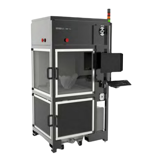
The Stratasys V650 Flex 3D printers incorporate the latest in innovative technology to provide you with precise prototypes from a CAD design. The V650 Flex 3D printer is capable of building parts up to 20 x 20 x 23 inches in size, using stereolithography technology. The printer’s open architecture allows it to be used with any commercially available resin. - Page 25 Printer Overview The following section contains images and descriptions of the main components and assemblies of the V650 Flex printer. Figure 1: V650 Flex Functional Components Page 18 © Copyright 2020 Stratasys. All rights reserved.
-
Page 26: Vat Lift Assembly
The vat lift assembly raises and lowers the resin vat into position and is used to maintain the resin at a consistent level while building parts. It consists of three machine screw jacks that are raised and lower by drive shafts powered by a stepper motor. Page 19 © Copyright 2020 Stratasys. All rights reserved. - Page 27 Figure 2: Vat Lift Assembly Vat Proximity Stepper Indicators (3) Motor Encoder Machine Screw Jacks (3) Page 20 © Copyright 2020 Stratasys. All rights reserved.
- Page 28 Vat Enclosure Vat Lift Assembly There are three proximity indicators that are used to prevent any over-travel of the vat. Figure 3: Vat Proximity Indicators Page 21 © Copyright 2020 Stratasys. All rights reserved.
- Page 29 The build chamber is visible through clear doors at the front and left side of the printer. It houses the following components: • Elevator Assembly • Build Platform • Recoater Assembly • Gauges (Laser Power Meter, Resin Level Sensor, Temperature Sensor) • Vacuum Enclosure Figure 4: Build Chamber Page 22 © Copyright 2020 Stratasys. All rights reserved.
-
Page 30: Elevator Assembly
The vertical movement of the platform is limited by proximity sensors, of which there are two sets, one each for full-size and half-size vats. Page 23 © Copyright 2020 Stratasys. All rights reserved. -
Page 31: Recoater Assembly
At the home position, the recoater blade must be clear of the elevator assembly with the platen installed, and of the Vat edges to allow proper motion of the elevator and Vat as required. Figure 6: Recoater Assembly Encoder Stepper Motor Page 24 © Copyright 2020 Stratasys. All rights reserved. - Page 32 The blade moves from front-to-rear-to-front after each layer of a part has been drawn by the laser. Adjustable sensors, located at the right side of the recoater assembly, limit the blade's movement. Page 25 © Copyright 2020 Stratasys. All rights reserved.
-
Page 33: Gauges
The resin level indicator monitors the height of the resin relative to that of the intended build surface. The temperature sensor monitors the temperature of the resin in the vat. Figure 8: Gauges Page 26 © Copyright 2020 Stratasys. All rights reserved. -
Page 34: Vacuum Enclosure
Access to the build enclosure is through two doors made of UV-filtering clear acrylic. Safety switches on both doors automatically stop the build process and shutter the laser if either door is opened while the machine is operating. Page 27 © Copyright 2020 Stratasys. All rights reserved. -
Page 35: Computer
10 minutes, after which time it will trigger a controlled shut down of the machine. The UPS must be turned off to ensure safe handling of any electrical components inside the electronics cabinet and printer. Page 28 © Copyright 2020 Stratasys. All rights reserved. - Page 36 Safe electrical practices must be followed by qualified trained personnel. See “Safety Instructions” (page 1). Remove all power before accessing the electronics cabinet including shutting off the UPS. Figure 11: Electronics Cabinet Access Door Page 29 © Copyright 2020 Stratasys. All rights reserved.
- Page 37 Cooling is provided by a fan located in the lower left corner of the enclosure. The fan pushes warm air out of this opening, causing fresh outside air to be drawn in through a filter at the upper right corner. Figure 13: Electronics Cabinet Cooling Page 30 © Copyright 2020 Stratasys. All rights reserved.
-
Page 38: Emi Filter (Part Number)
48VDC Power Supply (PWR-50003) Supplies power to all three stepper motors in the printer Vat Stepper Driver (DRV-50001) The stepper driver controls stepper motor operation. Figure 14: Vat Stepper Driver Progression Page 31 © Copyright 2020 Stratasys. All rights reserved. -
Page 39: Elevator Stepper Driver (Drv-50001)
Elevator Stepper Driver (DRV-50001) The stepper driver controls stepper motor operation. Figure 15: Elevator Stepper Driver Progression Recoater Stepper Driver (DRV-50001) The stepper driver controls stepper motor operation. Figure 16: Recoater Stepper Driver Progression Page 32 © Copyright 2020 Stratasys. All rights reserved. -
Page 40: Plc Cpu (Plc-50001)
Supplies power for the emergency stops, magnetic door switches, power indicator and Master Control relay. 5 VDC Power Supply The 5 volt DC power is used for the stepper pulses from the PLC Hi Speed Counters. Page 33 © Copyright 2020 Stratasys. All rights reserved. - Page 41 A fan, located at the right front corner of the enclosure, pulls fresh outside air into the enclosure through a filter located at the left rear corner. A sensor monitors the temperature inside the enclosure. Figure 17: Optical Enclosure Components Laser Head Page 34 © Copyright 2020 Stratasys. All rights reserved.
-
Page 42: Scanner Assembly
Laser Assembly The laser assembly consists of consists of a laser controller, laser head and an umbilical cable. Figure 18: Laser assembly Laser Controller Umbilical Cable Laser Head Page 35 © Copyright 2020 Stratasys. All rights reserved. -
Page 43: User Interface And Solidview Pro V650 Overview
SOLIDVIEW PRO V650 OVERVIEW This chapter provides an overview of the V650 Flex’s User Interface (UI) as well as all other user controls. These controls include buttons, key switches, and a touch-screen graphical user interface. Specific printer operation information and procedures can be found in... - Page 44 Controls and Indicators Emergency Stop Figure 1: Emergency Stop Buttons Page 37 © Copyright 2020 Stratasys. All rights reserved.
-
Page 45: Control Panel
Stop (via the Emergency Stop buttons)/Fault = alternately quick flashing red/amber, green • Idle = amber on, red/green off • Abort (via the user interface) = quick flashing red, amber/green off Page 38 © Copyright 2020 Stratasys. All rights reserved. -
Page 46: Optowave Laser Control Panel
Optowave Laser Control Panel • POWER ON: Red LED lights to indicate that the laser controller is powered up. • KEY SWITCH: Turns the laser controller on and off. Figure 4: Optowave Control Panel Page 39 © Copyright 2020 Stratasys. All rights reserved. - Page 47 Optowave Laser Control Panel Display Monitor, Keyboard and Mouse Besides the various Controls and Indicators described above, the V650 Flex is equipped with a touch-enabled monitor to allow users to interact with the machine. It is mounted on a swiveling arm just to the right of the front build chamber door.
- Page 48 The Home screen is outlined in red. The Home, Build, and Queue screens are similar to those in the operator's interface, but provide more functionality. Figure 6: Screen Hierarchy for Technician/Supervisor Interface Page 41 © Copyright 2020 Stratasys. All rights reserved.
- Page 49 The buttons change from screen to screen. On the Home screen, the Control Bar provides access Page 42 © Copyright 2020 Stratasys. All rights reserved.
- Page 50 Preview Display Tools: • Fit 1:1: Scales the image so that the entire 20x20-inch platform is displayed in the layer review pane (see the left-hand image in Figure 9 (page 44)). Page 43 © Copyright 2020 Stratasys. All rights reserved.
- Page 51 Depending on the password entered, the button changes to display the current user access level: • Operator : Allows you to select a job file, and start, stop, pause, or abort a job. Page 44 © Copyright 2020 Stratasys. All rights reserved.
- Page 52 Queue: Displays the Queue screen. From this screen, select a job file and move it to the top of the job queue. • Edit Job: Displays the Edit Job screen. From this screen, select which components are built and which are not. Page 45 © Copyright 2020 Stratasys. All rights reserved.
- Page 53 Percentage of Build Complete Field: self-explanatory Time Remaining Field: Tapping this field toggles between the total build time (displayed with a white background) and the remaining build time (displayed with a blue-green background). Page 46 © Copyright 2020 Stratasys. All rights reserved.
- Page 54 Edit Components: Displays the Edit Components screen (see Figure 14 (page 48)). • Modify Job: Displays the Edit Components screen (see Figure 14 (page 48)). • Back: Returns to the previous screen. Page 47 © Copyright 2020 Stratasys. All rights reserved.
- Page 55 The sliding control, between the Previous and Next buttons, allows you to go to any layer. The selected layer number is displayed in the field above the control. • First: Displays the first layer. Page 48 © Copyright 2020 Stratasys. All rights reserved.
- Page 56 Jobs can be added to Job Queue from either folder. • Change Folder: Takes you to C:\Stratasys Direct Manufacturing\Phoenix\Job Files. This screen has the following 3 buttons: •...
- Page 57 Build Actions/Settings Screen This screen displays the "Build Actions" and "Build Settings" control panes. Figure 16: Build Actions/Settings Screen • Back: Returns to the previous screen. Figure 17: Build Actions Pane Page 50 © Copyright 2020 Stratasys. All rights reserved.
- Page 58 Start Layer: Starts the job at the specified layer. • End Layer: Ends the job at the specified layer. Machine Settings Screen This screen displays the "Machine Settings," "Elevator Settings," and "User Settings" panes. Figure 19: Machine Settings Screen Page 51 © Copyright 2020 Stratasys. All rights reserved.
- Page 59 Material Name: Displays the type of resin being used. Tap the arrow at the right edge of the field to display a list of resins used by the machine, and select the desired resin. This list can be edited by Stratasys Support personnel. "Scaled" entries compensate for part shrinkage. A typical list follows.
- Page 60 4) Enter a unique password for the new user and confirm it. 4) Tap Save to create the new user account. • New Password: Enter a new password if desired. • Password Confirmation: self-explanatory Page 53 © Copyright 2020 Stratasys. All rights reserved.
- Page 61 There are also 3 buttons at the top of the screen that provide access to three additional screens: Material Settings, Lasing System, and Command Line. Figure 23: Maintenance Screen • Back: Returns to the previous screen. Figure 24: Elevator Pane Page 54 © Copyright 2020 Stratasys. All rights reserved.
- Page 62 • Go To…: Enter a positive value (in inches) in the adjacent field, and tap to move the recoater to that position. Page 55 © Copyright 2020 Stratasys. All rights reserved.
- Page 63 Unload: Lowers the platform slightly, moves the recoater to the home position, and raises the elevator (platform) to the home position. (Performs the same function as Unload on the Build screen.) Page 56 © Copyright 2020 Stratasys. All rights reserved.
- Page 64 • Open Shtr/Close Shtr: Toggles the laser shutter open and closed. If the shutter is closed, the button displays "Open Shtr." If the shutter is open, the button displays "Close Shtr." Page 57 © Copyright 2020 Stratasys. All rights reserved.
- Page 65 Preferred Blade Gap: Change the height of the recoater blade above the surface of the resin. This value is typically 0.004 inch. • Resin Scale Factor: Change the value used to compensate for resin shrinkage. • Back: Returns to the previous screen. Page 58 © Copyright 2020 Stratasys. All rights reserved.
- Page 66 Tap the Lasing System button in the Control bar of the Maintenance screen to display the laser and power meter controls. Figure 31: Lasing System Screen • Back: Returns to the previous screen Figure 32: Laser Pane Page 59 © Copyright 2020 Stratasys. All rights reserved.
- Page 67 The sliding control adjusts the duty cycle of the laser pulse, which is displayed in the right-hand field. • Pulse Rate: The pulse rate is factory set to 100KHz. WARNING: Do not change the pulse rate without the approval of stratasys engineering. • X Size/Size/Y Size: The measured beam size.
- Page 68 Tap the Command Line button in the Control bar of the Maintenance screen to display the command line screen. Enter commands in the Input field to align the laser and install the Calibration plate (refer to the V650 Flex On-site Installation and Setup Guide). Figure 34: Command Line Screen •...
- Page 69 Refer to “Fault Codes” (page 132) for a list of the possible faults and instructions for handling them. • Back: Returns to the previous screen. Page 62 © Copyright 2020 Stratasys. All rights reserved.
- Page 70 2. Click the Arrange button located in the lower right corner. Clicking this organizes the parts in the center of the build platform and .4 inches from the tray. Figure 36: Orient and Arrange STL Verify the proper vat size is chosen Page 63 © Copyright 2020 Stratasys. All rights reserved.
- Page 71 Optowave Laser Control Panel 3. Click Settings and select the correct resin and build style Figure 37: Select Settings 4. Click the Generate Supports button. 5. Click the Support button. Figure 38: Generate Supports Page 64 © Copyright 2020 Stratasys. All rights reserved.
- Page 72 Figure 39: Print Prep and Export Stereolithographpy Part Orientation To avoid the chance of the blade crashing a build, reduce the initial profile of the part geometry addressing the recoater blade. Figure 40: Single Part Orientation Page 65 © Copyright 2020 Stratasys. All rights reserved.
- Page 73 Figure 42: Avoiding Trapped Resin When building large parts, take care to fully support the parts and avoid part shrinking. It is also a best practice to avoid shallow angles. Figure 43: Large Part Orientation Page 66 © Copyright 2020 Stratasys. All rights reserved.
- Page 74 When building a part with organic curves, as with all additive manufacturing, layer stepping is an important concern. It is a best practice to orient the part vertically or at a 45 degree angle to reduce layer stepping. Figure 45: Layer Stepping Reduction Page 67 © Copyright 2020 Stratasys. All rights reserved.
- Page 75 Line width and spot size can speed up or slow down a build. • If a single sweep is used, do not build on the back of the platen. This will prevent blade shadow Page 68 © Copyright 2020 Stratasys. All rights reserved.
-
Page 76: Operating The Printer
Basic User Operations Powering ON the Printer 5 OPERATING THE PRINTER This chapter explains basic steps in operating the V650 Flex printer Warning: The Guarding System key switch must be enabled at all times during regular machine operation. Only a qualified technician or supervisor should bypass this safety feature. - Page 77 Some printers may require the login, User: tdguser | Password: Ok4tech18 (O is capital letter, not number) Make sure that sleep mode is disabled on the computer to prevent laser communication interruptions. Page 70 © Copyright 2020 Stratasys. All rights reserved.
- Page 78 Figure 3: Phoenix Login (Technician) 12. At the maintenance menu, select Lasing System. 13. At the laser panel, select the On options and make sure that the selection is activated. Figure 4: Laser System Menu Page 71 © Copyright 2020 Stratasys. All rights reserved.
-
Page 79: Powering On The Printer (Models No Longer In Production)
4. Power ON the scanner. 5. Power ON everything else, except the PC. 6. Power ON the PC. Wait a minimum of 10 minutes after the laser has started before operating the system. Page 72 © Copyright 2020 Stratasys. All rights reserved. -
Page 80: Powering Off The Printer
The emergency stop fault must be cleared in order to continue with a job. Figure 6: Emergency Stop Buttons Page 73 © Copyright 2020 Stratasys. All rights reserved. - Page 81 Loading and Replacing a Vat The information within this section will walk you through the process of loading and replacing the vat for the V650 Flex printer. 1. If a build is in progress, stop the build and remove the build platform and part.
- Page 82 6. Access the Maintenance screen and press and hold (vat pane) Move up until the jack heads just contact the lifting brackets. Page 75 © Copyright 2020 Stratasys. All rights reserved.
- Page 83 Note: When aligning the vat, pay particular attention to the alignment of the forward edge of the vat and the recoater blade. Figure 11: Aligning the Vat to the Recoater Rim Page 76 © Copyright 2020 Stratasys. All rights reserved.
-
Page 84: Loading A Job
Loading a Job Loading a Job 1. Launch the Phoenix user interface, or tap the Back button if the interface is running, to display the Home screen. Figure 12: Home Screen Page 77 © Copyright 2020 Stratasys. All rights reserved. - Page 85 6. Tap Back to return to the Home screen. 7. Tap Next Job to load the job file. 8. Check the Status bar and verify that the correct job file was loaded. Page 78 © Copyright 2020 Stratasys. All rights reserved.
-
Page 86: Previewing A Job
5. Tap Fit 1:1 to scale the image of the build layer so that the entire 20x20-inch platform is displayed within the layer review pane. See the left image in Figure Page 79 © Copyright 2020 Stratasys. All rights reserved. -
Page 87: Starting A Build
(see the left image detail). Figure 16: Installing the Build Platform 2. Launch the Phoenix user interface, or tap the Back button if the interface is already running. The Home screen displays. Page 80 © Copyright 2020 Stratasys. All rights reserved. - Page 88 6. 6.Inspect the field at the bottom left corner of the screen and verify that the correct job file is displayed. If necessary, refer to Figure 17 (page 81) to select and load the correct file. Page 81 © Copyright 2020 Stratasys. All rights reserved.
-
Page 89: Monitoring The Print Job
All information pertaining to the job in progress is displayed in the Information panel at the right side of the Build screen. This information includes Machine Settings, Build Information, Layer Information, and Block Data. Page 82 © Copyright 2020 Stratasys. All rights reserved. -
Page 90: Stacklight Signals And On-Screen Status
Unload. When the job has completed and the machine status is Idle, open the left-hand upper access door and release the spring-loaded latch. Refer to Figure 16 (page 80). Remove the build platform from the machine. Page 83 © Copyright 2020 Stratasys. All rights reserved. -
Page 91: Clearing A Fault
If the job is salvageable, take note of the current layer and resume the job from that layer by navigating to the Build Settings pane (see Figure 17 (page 81)). Set Initialize Platform at Start to OFF, and set the Start Layer to the last layer built. Page 84 © Copyright 2020 Stratasys. All rights reserved. -
Page 92: Advanced Operations
Select Material and Update Parameters The Machine Settings pane allows you to select a resin type, specify the X and Y scale factors, and set the maximum border and hatch speeds. Page 85 © Copyright 2020 Stratasys. All rights reserved. - Page 93 System screen. The Laser pane displays the laser power settings. The operating current and pulse rate are factory set and should not be changed without consulting Stratasys service. The only editable setting is the duty cycle. Move the sliding control, to the right of the Power field, to change the duty cycle.
-
Page 94: Calibration And Adjustments
Required Tools and Equipment 6 CALIBRATION AND ADJUSTMENTS This chapter describes basic calibration and adjustment procedures for the V650 Flex. Required Tools and Equipment • Liquid Level Calibration Bracket (with indicator) • 004-inch (0.101-mm) and .005-inch (0.127-mm) flat feeler gauges •... - Page 95 Figure 2. Note the meniscus that forms just as the tip of the probe breaks the surface of the resin. Figure 2: Setting the Resin Level 6. Close the Phoenix software. Page 88 © Copyright 2020 Stratasys. All rights reserved.
- Page 96 10. Click View Measurement Value to open the Measurement Value Display window. 11. Click Measurement value acquisition start. 12. When values are displayed in the OUT1 and OUT2 fields (as shown in Figure 4), click Zero(1) and Zero(4). Page 89 © Copyright 2020 Stratasys. All rights reserved.
- Page 97 The following procedure is part of the initial printer setup and, for the printer operator, should be seen as necessary training for basic printer operation. If the user has not received training in this area, please contact Stratasys support for assistance in performing this calibration.
- Page 98 Recoater Blade Rake Check and Adjustment 3. Remove the vacuum hose from the left side of the recoater blade. Figure 5: Removing the Vacuum Hose from the Recoater Blade Page 91 © Copyright 2020 Stratasys. All rights reserved.
- Page 99 5. Visually inspect the level to ensure that the blade is perpendicular to the platform. If the bubble is centered, the check is complete. If the blade has any rake (bubbles not exactly centered), continue to the next step. Figure 7: Checking the Recoater Blade Rake Page 92 © Copyright 2020 Stratasys. All rights reserved.
- Page 100 11. Use a 3/32” hex wrench to adjust the 2 rake adjustment screws until the bubble in the level is centered. Figure 9: Adjusting the Recoater Blade Rake Rake Adjustment Recoater Screws Blade Page 93 © Copyright 2020 Stratasys. All rights reserved.
- Page 101 There are two types of gapcheck file. One, which has two strips, is as noted below. An alternate file, containing six boxes for verifying the blade gap, is used for more viscous resins. The process for both types of gapcheck file is the same. Page 94 © Copyright 2020 Stratasys. All rights reserved.
- Page 102 8. Manually pull on the chain at the front of the recoater rim to move the recoater blade to the rear of the platform. Page 95 © Copyright 2020 Stratasys. All rights reserved.
- Page 103 10. Check the gap at the back, middle and the front of the platform. 11. If the clearance between the blade and both rails is 0.004inch (0.101mm) and uniform, skip to Step 22. If the clearance must be adjusted, continue to the next step. Page 96 © Copyright 2020 Stratasys. All rights reserved.
- Page 104 16. If the clearances at all 3 positions are at least 0.004 inch (0.101 mm) and uniform, go to Step 22. If the clearances vary from front to back, continue to the next step to realign the recoater rim. Page 97 © Copyright 2020 Stratasys. All rights reserved.
-
Page 105: Line-Width Mapping "Roots" Parts
Command Line page. 2. In the command line, type “pfbst” and click Enter. Verify that the values returned are 1:1 for 0.005, 0.010, 0.015, 0.020, 0.025 and 0.032. Page 98 © Copyright 2020 Stratasys. All rights reserved. - Page 106 15 minutes or until the part does not feel tacky or sticky. 11. After the parts have completed the post-cure process, measure the "X" part at locations A, B and C, as shown in Figure Figure 15: “Root” Measurement Points Page 99 © Copyright 2020 Stratasys. All rights reserved.
- Page 107 Figure 17: “Root” Measurement Worksheet A, B and C Values 15. Add the values for A and B, then subtract the value of C from their sum: (A+B)-C = Line Width. For example: (0.2592 + 0.2587) - 0.508 = 0.0099. Page 100 © Copyright 2020 Stratasys. All rights reserved.
- Page 108 17. Add the values for D and E, then subtract the value of F from their sum: (D+E)-F = Line Width. In this example, the target line width = 0.10” (0.254mm). (0.2585 + 0.2588) - 0.5078 = 0.0095. Page 101 © Copyright 2020 Stratasys. All rights reserved.
- Page 109 ±0.0015 of the target (0.010). If the part now averages 0.008, then subtract 0.002 from the values previously entered in the step 24 and input the new values through the Command Line. Page 102 © Copyright 2020 Stratasys. All rights reserved.
-
Page 110: Resin Shrinkage "Tree" Parts
Figure 19: Machine Settings: X and Y Scale Factors 1. Build 2 resin shrinkage “tree” parts (X and Y) using the "Axis-Shrink-Position-15in.stl" job file. 2. Clean the parts and place them on a table. Page 103 © Copyright 2020 Stratasys. All rights reserved. - Page 111 Use the 15 inch tree shrinkage spreadsheet to automate the process or use the formula, =SUM(-SLOPE(X1:X7,Y1:Y7)). The result can be subtracted from, or added to 1.000. for example a slope of -0.0024 for Y would result in shrink of 0.9976. Page 104 © Copyright 2020 Stratasys. All rights reserved.
- Page 112 6. At the V650 machine setting menu, input the scale factors into the Scale Factor X: and Scale Factor Y: fields. Figure 21: V650 Machine Settings 7. Repeat this procedure for the "Y" part. Page 105 © Copyright 2020 Stratasys. All rights reserved.
- Page 113 Validation Resin Shrinkage “Tree” Parts Table 1: “Christmas Tree” Measurment Worksheet Expected Actual Measurements Average Error Measurement X-Axis Part 15.0 10.0 0.25 Y-Axis Part 15.0 10.0 0.25 Page 106 © Copyright 2020 Stratasys. All rights reserved.
-
Page 114: Maintenance
V650 Flex. Detailed instructions for each task make up the rest of this chapter. With the exception of Clean Recoater Blade and Check Vacuum Level, the V650 Flex printer must be powered down when performing the procedures listed below. -
Page 115: Clean Fan Filter
Monthly Maintenance Clean Fan Filter Monthly Maintenance Clean Fan Filter The V650 Flex has two cooling fans and two air intakes. See Figure 1. Both the fans and the intakes have foam filters that should be cleaned monthly with compressed air. -
Page 116: Clean Power Meter Window And Replace Washer
• Metric Allen wrenches • 99% isopropyl alcohol • Lens tissues • Nitrile gloves 1. Remove the center elevator guard by removing eight screws. Figure 3: Removing the Center Elevator Guard Page 109 © Copyright 2020 Stratasys. All rights reserved. - Page 117 Figure 4: Power Meter Assembly 3. Remove the base from the power meter and clean the fused silica window using a lens tissue moistened with isopropyl alcohol. Figure 5: Power Meter Window Page 110 © Copyright 2020 Stratasys. All rights reserved.
- Page 118 Step 2. Ensure that the domed side of the washers face the screw heads. Figure 7: Power Meter Window Assembly 6. Reinstall the rear elevator cover. Page 111 © Copyright 2020 Stratasys. All rights reserved.
-
Page 119: Clean Laser Window
Use caution when tightening screws. Do not over-tighten. Tighten all screws evenly to prevent damage to the glass. 4. Reinstall the window, taking care not to touch the glass. Ensure that the window-holder reference marks are aligned before reattaching the four screws. Page 112 © Copyright 2020 Stratasys. All rights reserved. -
Page 120: Clean Recoater Blade
9, and run your hand along the bottom of the recoater blade to check for surface irregularities (i.e. debris on the blade's bottom edge). If no debris is felt, skip to Step 5. Otherwise, continue to the next step. Figure 9: Checking for Debris Page 113 © Copyright 2020 Stratasys. All rights reserved. - Page 121 Figure 11: Bottom of Recoater Blade 6. If the blade is either clean or blade removal is not required for cleaning, this process is complete. If it is difficult to clean, then proceed to step 7. Page 114 © Copyright 2020 Stratasys. All rights reserved.
- Page 122 7. Remove the vacuum hose from the left side of the recoater blade. 8. Unfasten the captive thumbscrews and remove the right and left caps (with the compression springs) from the blade support assemblies. Figure 12: Remove blade support caps Page 115 © Copyright 2020 Stratasys. All rights reserved.
- Page 123 9. Lift the recoater blade out of the blade support assemblies. Figure 13: Remove recoater blade Clean the bottom of the blade as required. Reinstall the blade. 11. Position the vat and elevator for the start of a build. Page 116 © Copyright 2020 Stratasys. All rights reserved.
-
Page 124: Clean Level Sensor Baffle
Figure 14: Cleaning the Level Sensor Baffle 4. Position the vat and elevator for the start of a build. Page 117 © Copyright 2020 Stratasys. All rights reserved. -
Page 125: Check Vacuum Level
4. While closely observing the resin level in the recoater blade window, slowly and evenly turn the vacuum flow control valves clockwise to increase vacuum. Increase vacuum until the resin level is at the center of the recoater blade window (see Figure 16). Page 118 © Copyright 2020 Stratasys. All rights reserved. - Page 126 As Needed Maintenance Check Vacuum Level 5. Use recoater blade flow control valve for any fine adjustments to the resin level. Figure 16: Recoater Blade Window Page 119 © Copyright 2020 Stratasys. All rights reserved.
-
Page 127: Recoater Blade Compression Spring Replacement
1. Power OFF the printer, see “Powering OFF the Printer” (page 73). 2. Release the captive knurled thumb screw and remove the top cap from the blade support assembly. Figure 17: Top Cap Page 120 © Copyright 2020 Stratasys. All rights reserved. - Page 128 Figure 18: Compression Spring 3. After replacing the spring, reinstall the top cap onto the split pin protruding from the upper edge of the housing holder, and the knurled thumb screw. Page 121 © Copyright 2020 Stratasys. All rights reserved.
-
Page 129: Power Meter Window Replacement Kit
Figure 19: Removing the Center Elevator Guard 3. Unfasten two M2.5 button head cap screws and remove the cap from the top of the power meter. Figure 20: Power Meter Window Page 122 © Copyright 2020 Stratasys. All rights reserved. - Page 130 5. Insert a 1-inch (25.4-mm) silicon O-ring in the groove in the bottom of the knife edge base. Figure 21: Silicon O-ring in Groove 6. Clean the aperture washer and insert it into the top of the knife edge base. Figure 22: Clean Aperture Washer Page 123 © Copyright 2020 Stratasys. All rights reserved.
- Page 131 Figure 23: Fused Silica Window 8. Insert a 10-mm (25/64-inch) silicon O-ring in the groove in the bottom of the knife edge cap. Figure 24: 10mm O-ring in Groove Page 124 © Copyright 2020 Stratasys. All rights reserved.
- Page 132 Step 2. Ensure that the domed side of the washers face the screw heads. Figure 25: Install Cap 10. Reinstall the rear elevator cover Page 125 © Copyright 2020 Stratasys. All rights reserved.
-
Page 133: Recoater Blade Air Flow Control Valve, Breather Vent, And Cap
2. The air flow control valve, breather vent and cap are threaded into the top of the recoater blade. Unscrew the components to remove. Figure 26: Recoater Blade Valve, Vent, and Cap Page 126 © Copyright 2020 Stratasys. All rights reserved. -
Page 134: Platform Locating Pin And Set Screw
3. Release the platform latch and remove the platform, if present. 4. The 2 platform locating pins are held in the elevator fork assembly by set screws, as shown Figure 27 (page 127). Figure 27: Platform Locating Pins Page 127 © Copyright 2020 Stratasys. All rights reserved. -
Page 135: Screw Jack Support Shim
Screw Jack Support Shim Procedure Note: This procedure applies to new Stratasys vats that have not yet been fitted to the V650 Flex. 1. If there is a vat installed, remove the vat from the machine. 2. Roll the new (empty) vat into the vat enclosure. Raise the vat lift assembly until the jacks engage the vat support brackets. -
Page 136: Stacklight Elements And Horn
See Figure Figure 30: Stacklight Base and LED Assembly Page 129 © Copyright 2020 Stratasys. All rights reserved. -
Page 137: Ups System
The UPS system rests unsecured on the computer base plate in the computer bay. Disconnect it from all of the AC components, and then remove it. Figure 31: UPS and PC in Computer Bay Page 130 © Copyright 2020 Stratasys. All rights reserved. -
Page 138: Led Light Fixture
LED Light Fixture LED Light Fixture Procedure Unplug the light fixture to be replaced and unsnap it from the two mounting brackets. Installation is the reverse. Figure 32: LED Light Fixtures Page 131 © Copyright 2020 Stratasys. All rights reserved. -
Page 139: Troubleshooting
If you have a problem with your printer or the printer’s materials that is not covered in this guide, or if you need to order replacement parts, please contact Customer Support for your region. Contact information is available from the Stratasys website at: http://www.stratasys.com/customer-support/contact-customer-support. - Page 140 ELV Homing Move recoater out of the Attempt to home elevator 2009 unsafe - Recoater way before attempting to while recoater is in the way. in way move elevator Page 133 © Copyright 2020 Stratasys. All rights reserved.
- Page 141 Limit sensor may have RCT Move limit Recoater ran into hard 3004 come loose. Contact found (sensor) limit. Technical Support. RCT Ctrio cmd 3005 Internal Error Contact Technical Support error Page 134 © Copyright 2020 Stratasys. All rights reserved.
- Page 142 Possible obstruction or 3015 Contact Technical Support > 15secs resin in vacuum line. RCT Invalid Use valid speed for move 3016 Invalid speed value. DynPos speed (0) task (0 is invalid). Page 135 © Copyright 2020 Stratasys. All rights reserved.
- Page 143 VAT Homing - unexpected load or binding. 4010 unexpected Vat may be jammed. If none found, contact encoder stoppage Technical Support. VAT Unexpected 4011 Internal Error Contact Technical Support. negative position Page 136 © Copyright 2020 Stratasys. All rights reserved.
- Page 144 - Contact RL level high Unexpected resin position Technical Support. 5007 REMOVE RESIN detected. Reattempt move. Contact RL Leveling move Levelling move taking too 5008 Technical Support if fault timeout long. persists. Page 137 © Copyright 2020 Stratasys. All rights reserved.
- Page 145 Allow laser to cool down 8003 Temperature Too System overheated. before attempting to restart. High Laser Head Bring environment within 8004 Temperature Too System too cold to start. operating range before attempting start. Page 138 © Copyright 2020 Stratasys. All rights reserved.
- Page 146 Internal Error Internal Firmware 9005 Internal Error Contact Technical Support Write Digital Bad 9006 Internal Error Argument Laser Power Bad 9007 Internal Error Argument Correction Table 9008 Internal Error Bad Argument Page 139 © Copyright 2020 Stratasys. All rights reserved.
- Page 147 Internal Error Detected 9021 Undefined Internal Error Contact Technical Support Write Analog Bad 9022 Internal Error Argument Transform Enable 9023 Internal Error Bad Argument Transform Matrix 9024 Internal Error Bad Argument Page 140 © Copyright 2020 Stratasys. All rights reserved.
- Page 148 Power Failure 1. In the event of a power failure, the UPS will automatically supply power to the V650 Flex. If a build is in progress, it will continue until the UPS battery charge drops below 66%, at which point the build will be paused by software. The build will remain paused until power is restored, and the UPS battery charge has reached 75%, at which point the build will automatically resume.
-
Page 149: Supplementary Information
Build Parameters Pane: Tap the build parameter that you wish to edit. The Edit Parameters button at the right of the screen becomes active. Tap Edit Parameters to display the parameters that you can edit. Page 142 © Copyright 2020 Stratasys. All rights reserved. -
Page 150: Edit Parameters Screens
Figure 2: Edit Parameters Screens • Undo: Reverts all edited parameters to the original values. • Save: Saves all edited parameter values. • Back: Returns to the previous screen. Declaration of Conformity Page 143 © Copyright 2020 Stratasys. All rights reserved. -
Page 151: Emc Class A Warning
Caution: Pursuant to Part 15.21 of the FCC Rules, any changes or modifications to this equipment not expressly approved by Stratasys, ltd. may cause harmful interference and void the FCC authorization to operate this equipment. This equipment has been tested and found to comply with the limits for a Class A digital device, pursuant to Part 15 of the FCC Rules. -
Page 152: Msds (Material Safety Data Sheet)
Regulatory and Environmental Information MSDS (Material Safety Data Sheet) MSDS (Material Safety Data Sheet) You can obtain current Material Safety Data Sheets for printer materials from the Stratasys website at: http://www.stratasys.com/materials/material-safety-data-sheets. Disposal of Waste Equipment by Users in Private Households in the European Union This symbol on the product or on its packaging indicates that this product must not be disposed of with your other household waste. - Page 153 _____ c-support@stratasys.com Copyright © 2020 Stratasys Ltd. All rights reserved. 407388-0001_REV_A THE 3D PRINTING SOLUTIONS COMPANY...
Need help?
Do you have a question about the V650 Flex and is the answer not in the manual?
Questions and answers