Table of Contents
Advertisement
Quick Links
Advertisement
Table of Contents

Subscribe to Our Youtube Channel
Related Manuals for Stratasys V650 Flex


Summary of Contents for Stratasys V650 Flex
- Page 1 Site Preparation Guide V650 Flex 3D Printing System Part No. 408599-0001_REV_A...
- Page 2 No part of this document may be photocopied, reproduced, or translated into any human or computer language in any form, nor stored in a database or retrieval system, without prior permission in writing from Stratasys. This document may be printed for internal use only. All copies, shall contain a full copy of this copyright notice.
-
Page 3: Table Of Contents
Contents Revision Log ....................iv Safety......................iv Safe Environment........................ iv About the V650 Flex Printer................1 Components ........................1 How to Use This Guide......................2 Site Prep Tasks ....................2 Selecting the Site ........................ 2 Physical Specifications and Space Requirements .............. 3 Environmental Requirements .................... -
Page 4: Revision Log
The following basic safety tips are given to ensure safe installation, operation, and maintenance of Stratasys equipment and are not to be considered as comprehensive on matters of safety. Although the V650 Flex printers are designed to be safe and reliable, access to areas of the printer are potentially dangerous. -
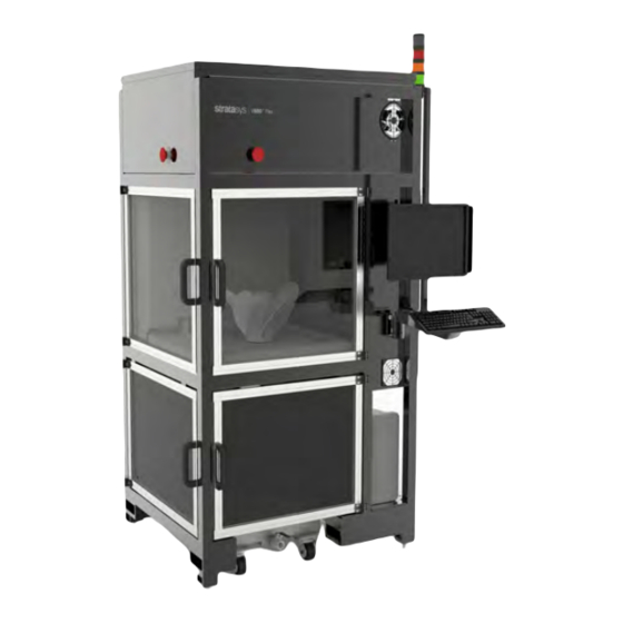
Page 5: About The V650 Flex Printer
The Stratasys V650 Flex 3D printers incorporate the latest in innovative technology to provide you with precise prototypes from a CAD design. The V650 Flex 3D printer is capable of building parts up to 20 x 20 x 23 inches in size, using stereolithography technology. The printer’s open architecture allows it to be used with any commercially available resin. -
Page 6: How To Use This Guide
Site Prep Tasks Selecting the Site The V650 Flex printer does not have casters. Due to the size of the printer, a forklift is required to move the system to an un-boxing location and to the final selected installation site. -
Page 7: Physical Specifications And Space Requirements
Width: 54.5 inches (138 cm) Uncrated Depth: 48.5 inches (123 cm) (Closed Covers and Panels) Height w/Stacklight: 92.6 inches (235 cm) Shipping Weight (crated) 2200 pounds (998 kg) Printer Weight (uncrated) 1700 pounds (771 kg) Figure 1: V650 Flex Dimensions Page 3... - Page 8 Site Preparation Guide Site Prep Tasks Figure 2: V650 Flex Center of Mass The center of mass dimensions shown are taken from the bottom center of the front left foot. Page 4...
- Page 9 Site Preparation Guide Site Prep Tasks Minimum Space Requirements Sufficient rear clearance will allow access to the power connector and maintenance, while sufficient clearance on all sides and top will allow enough room to fully open doors and covers. Additional room in the front is recommended to allow for easy positioning of the resin-filled vat (27.5 inches wide x 29.5 inches deep x 33 inches high).
- Page 10 Figure 4: Minimum Space (Top) The minimum height requirement of 105 inches (266cm) must be met in order to install the V650 Flex printer. No installation should proceed without verification of the minimum 105 inches of clearance from the floor to the ceiling.
-
Page 11: Environmental Requirements
Material storage shall be in the range of 55°F to 86°F (13°C to 30°C), with relative humidity less than 70%. Heat Output The following information may be used for preparing the site to handle the V650 Flex printer’s heat output. It is provided to assist in correctly sizing the site’s HVAC system. •... - Page 12 Site Preparation Guide Site Prep Tasks Figure 5: Laser Chamber Figure 6: Air Out Cutout Page 8...
-
Page 13: Electrical Requirements
Voltage: 100-132 VAC • Current: 15/7A • The V650 Flex uses standard 120V, 15A power input. The power cord is coiled inside the computer bay (Figure 7), allowing a qualified electrician to connect the printer to a facility power source. -
Page 14: Controller And Workstation Requirements
Controller and Workstation Requirements The V650 Flex printer is supplied with a PC as its main controller. To operate the machine, a user with sufficient rights needs to log into the PC. The printer comes setup with a preset local user named 'Operator'. -
Page 15: Receiving The Printer
Receiving the Printer Inspect Crate for Damage Before opening the shipping crate, inspect the crate for signs of exterior damage. Report evidence of excessive damage to Stratasys and the shipping company. Preparing For Installation Required Tools and Equipment Arrival of all required items for installation (tools crib, materials, system and finishing equipment) must be on site and verified a minimum of 3 days before installation. -
Page 16: Unpacking The Printer
Site Preparation Guide Preparing For Installation Unpacking the Printer The panels of the V650 Flex printer shipping crate are marked “Front”, “Back”, “Left”, “Right” “Top” and “Bottom”. The marked panels will correspond with the sides of the V650 printer inside. - Page 17 Site Preparation Guide Preparing For Installation 2. Using a Phillips screwdriver (or drill with Phillips bit), remove the screws (12) that secure the front panel to the crate (Figure 9). Remove and set aside the front of the crate to be reassembled/packed for storage.
- Page 18 Site Preparation Guide Preparing For Installation 3. Remove the screws that secure the left, right and rear panels to the shipping crate base. 4. Slide the remaining left, right, rear and top crate panels (still assembled) back until they are free of the shipping crate base (Figure 10).
- Page 19 Site Preparation Guide Preparing For Installation 5. Use the cutters to remove the cable ties restraining the two shipping strap ratchets (Figure 11). 6. Use the corner strap ratchets to loosen and remove the two shipping straps. 7. Using a utility knife, carefully cut away and remove the plastic shrink wrap surrounding the printer.
- Page 20 Site Preparation Guide Preparing For Installation Remove Printer from Shipping Base 1. If necessary, install extensions to the forklift so that forks are at least 4 feet long. 2. Spread the forklift forks to 29 inches to fit inside the structural lifting tubes on the printer base (Figure 12).
- Page 21 “Physical Specifications and Space Requirements” (page 3). Refer to Chapter 2 of the V650 Flex User Guide for final setup instructions. 5. Inspect the printer’s exterior for dents and scratches. Immediately report any damage to Stratasys and the shipping company.
-
Page 22: Unpacking The Resin Vat
Site Preparation Guide Preparing For Installation Unpacking the Resin Vat 1. Remove the top and front panels from the vat shipping crate. 2. From the bottom front of the resin vat, use a m6 hex nut driver to remove the lag screws (2) securing the vat restraining brackets (2) to the shipping crate base (Figure 13). -
Page 23: Site Preparation Checklist
Site Preparation Guide Site Preparation Checklist Site Preparation Checklist Electrical Installation Requirements • A dedicated outlet of 100-132 VAC~15-7A 50/60 Hz has been installed. • The grounded electrical outlet is within 2 meters (80 inches) of the printer. • The grounded electrical outlet is able to accept a US power cord plug. •... - Page 24 _____ c-support@stratasys.com THE 3D PRINTING SOLUTIONS COMPANY...
Need help?
Do you have a question about the V650 Flex and is the answer not in the manual?
Questions and answers