Table of Contents
Advertisement
Quick Links
Download this manual
See also:
User Manual
Advertisement
Table of Contents
Troubleshooting

Related Manuals for Stratasys uPrint


Summary of Contents for Stratasys uPrint
- Page 1 Plus ® ® uPrint SE and uPrint SE Plus ® ® Service Manual Part No. 209010-0001, Rev D...
- Page 2 Dimension BST, Dimension SST, WaveWash, and Ecoworks are registered trademarks of Stratasys Inc. FDM Technology, Fused Deposition Modeling, ABSplus, Catalyst EX, and Smart Supports are trademarks of Stratasys, Inc. All other trademarks are the property of their respective owners, and Stratasys assumes no responsibility with regard to the selection, performance, or use of these non-Stratasys products.
- Page 3 About This Guide This service guide is designed to help you easily find the information you need to successfully service Dimension BST and SST systems. This guide is arranged in chapters with tabs for easy reference. When viewing the electronic PDF version, you can easily hyperlink to specific headings or chapters using the following methods: •...
-
Page 4: Table Of Contents
Table of Contents Safety _______________________________________________________ 1-1 Hazard Classifications ________________________________________________________ 1-1 Product Safety Symbols_______________________________________________________ 1-1 Safety Devices _______________________________________________________________ 1-1 System Overview ____________________________________________ 2-1 What happens when...________________________________________________________ 2-2 Powering up _____________________________________________________________ 2-2 Powering Down __________________________________________________________ 2-3 Loading Material _________________________________________________________ 2-3 Building a Part____________________________________________________________ 2-3 Electronics Overview _________________________________________________________ 2-5 Single Board Computer ___________________________________________________ 2-6 Controller Board__________________________________________________________ 2-7... - Page 5 Software _____________________________________________________ 3-1 Software Architecture ________________________________________________________ 3-2 Operating System ________________________________________________________ 3-2 Display Driver_____________________________________________________________ 3-2 Comm Server ____________________________________________________________ 3-2 System Manager _________________________________________________________ 3-3 Move Compiler __________________________________________________________ 3-3 Feeder___________________________________________________________________ 3-3 Event/Command Monitor_________________________________________________ 3-3 DataStatEX __________________________________________________________________ 3-4 CatalystEX ___________________________________________________________________ 3-5 CatalystEX Overview _____________________________________________________ 3-5 Conventional Help File ____________________________________________________ 3-5 Dynamic Help ____________________________________________________________ 3-5 MaracaEX Help ______________________________________________________________ 3-6...
- Page 6 Maintenance Preparation ____________________________________________________ 4-3 Read these warnings before performing service on printer!______________ 4-3 Required Tools list ____________________________________________________________ 4-4 Distributer/Reseller supplied Tools __________________________________________ 4-4 Supplied by Stratasys _____________________________________________________ 4-4 Pre-Maintenance Procedures _________________________________________________ 4-4 Exterior Components _________________________________________________________ 4-5 Top Panel ________________________________________________________________ 4-5...
- Page 7 Y EOT (End of Travel) Sensor ______________________________________________ 4-92 X Motor _________________________________________________________________ 4-93 Y Motor ________________________________________________________________ 4-100 Y Motor Belt ____________________________________________________________ 4-103 Y Drive Rod ____________________________________________________________ 4-110 XY Table _______________________________________________________________ 4-117 Z Stage Components ______________________________________________________ 4-137 Z Home Sensor _________________________________________________________ 4-137 Z EOT (End of Travel) Sensor _____________________________________________ 4-138 Chamber Fans _________________________________________________________ 4-139 Chamber Heaters ______________________________________________________ 4-141...
- Page 8 Controller Initialization Failed Minor Errors (19.XX) _______________________ 6-24 Door Unlatch Failed (20.XX)___________________________________________ 6-24 Controller Communications Failed Sub Errors (22.XX) ___________________ 6-24 Universal Device Name Error (23.XX) __________________________________ 6-24 3.0 Non-Code Errors _____________________________________________________ 6-25 What happens during Power Up / Boot________________________________ 6-33 4.0 Connector Pinouts and Signals________________________________________ 6-40 Umbilical cable diagram _____________________________________________ 6-40 Umbilical cable pinouts ______________________________________________ 6-41...
- Page 9 Illustrated Parts List ___________________________________________ 8-1 Front Door Area Components _________________________________________________ 8-2 Electronics Bay Components _________________________________________________ 8-3 Head Area Components _____________________________________________________ 8-5 XY Table Area Components __________________________________________________ 8-8 Z Stage Area Components___________________________________________________ 8-10 Chamber Heater Area components __________________________________________ 8-11 Material Bay ________________________________________________________________ 8-12 Cables _____________________________________________________________________ 8-13 Checklists ___________________________________________________ 9-1 Hard Drive Installation Checklist_______________________________________________ 9-2...
-
Page 10: Safety
• Liquefier T/C alarm – activated for a bad or missing thermocouple • Power shut down signal from the PDB – activated if any thermal limit switches trip • Thermal snap switch located on the Head Board. • Main thermal fuse uPrint/uPrint SE Service Manual... -
Page 12: System Overview
LEDs__________________________________________________________ 2-11 Power Distribution Board (PDB) ____________________________________ 2-12 Chamber Temperature Control ________________________________ 2-13 Test Points and LED’s __________________________________________ 2-13 I/O Card _________________________________________________________ 2-16 Head Board ______________________________________________________ 2-17 Printer overview _____________________________________________________ 2-18 Finding more information ___________________________________________ 2-23 uPrint/uPrint SE Service Manual... -
Page 13: What Happens When
What happens when... Powering up Once the unit is ready to build, the display will show (no part in the queue) or Idle Ready to followed by the part name. Once a part is started the appropriate liquefier will begin to build heat. -
Page 14: Powering Down
From the printer, press the button to begin building the displayed part. Start Model Remote - You send a part to the printer from your CatalystEX ‘Start Model’: work station. The part automatically begins to build. uPrint/uPrint SE Service Manual... - Page 15 From the printer, press the button. Wait for Part Note: Make sure an empty modeling base is installed, then answer to the prompt Is Model Base Installed? is displayed in the upper window. Press to exit Wait for Part Cancel if you wish the remote start mode.
-
Page 16: Electronics Overview
Electronics Overview Figure 2-1: Electronics Overview detail Controller Board Support heater +120 +5 and +12 VDC power +24 VDC VDC Power supply power supply Supply AC Input 120-240 VAC 120-240 VAC uPrint/uPrint SE Service Manual... -
Page 17: Single Board Computer
Single Board Computer The single board computer (SBC) is the main processor in the system. See Figure 2-2. showing the board layout. The TCP/IP network interface connects directly to the RJ-45 connector on the SBC. The network interface supports both 10baseT and 100baseT operation. The hardware differentiates automatically. -
Page 18: Controller Board
Their position and rotation are precisely known at all times. Temperature Control The controller board reads the three thermocouple (T/C) inputs/signals - 2 for the head, 1 for the chamber. uPrint/uPrint SE Service Manual... -
Page 19: Liquefier Temperature Control
Liquefier Temperature Control The liquefier T/C connects to the controller board through the power distribution board. The T/C generates a variable low level current that depends on the temperature of the T/C. This analog signal from the T/C is amplified by the head distribution. It is then sent down the umbilical cable to the PDB, and then to the controller board. -
Page 20: Actuators, Switches & Optical Sensors
The input and output signals are passed through the PDB and then processed by the controller board. The non-motor actuators on a uPrint system are 24 volt solenoids. The 24 volt power is supplied by the PDB which in turn is controlled by the controller board. The following is a list of actuators: •... -
Page 21: Reset Button
Figure 2-4: Controller board connection detail Reset Button Located on the lower right side of the board, the reset button will do a hard reset of the controller board. Before continuing with normal operation after resetting the board, system power must be cycled before building. The reset button should only be used after using TeraTerm. -
Page 22: Sw6
During normal operation, D13 will blink approximately once every two seconds to indicate that the watchdog is monitoring the system and everything is operational. LED Label Description +3.3 VDC Supply +5 VDC Supply +12 VDC Supply D6-D12 Debug LEDs (software use only) Coldfire processor heartbeat uPrint/uPrint SE Service Manual 2-11... -
Page 23: Power Distribution Board (Pdb)
Power Distribution Board (PDB) Figure 2-5: PDB Detail AC Power In Power Switch/Thermostat Chamber Heaters Auxiliary 120VDC power supply Z BOT, Z EOT, Chamber Fans, Frame ID, Filament detect sensor (not used) Z motor I/O board connection I/O board connection 24VDC input Test points and LEDs (see detail in this section) 5/12VDC input... -
Page 24: Chamber Temperature Control
TP20 for support, and TP28 for the chamber NOTE: 10 mV = 1 degree C. Test Points and LED’s Test points and LED’s are very useful for troubleshooting the system. The test points and LED’s are listed below with a brief description. See Figure 2-6. Figure 2-7. uPrint/uPrint SE Service Manual 2-13... - Page 25 Figure 2-6: Test points and LEDs detail Component Test Pt Description TP29 Power fail signal from external UPS +5V REF TP24 Head T/C service reference Door Switch TP15 State of the door (open or closed) On/Off Switch TP14 State of power down switch Power Enable Enables power to circuitry (normally high) Model Toggle...
- Page 26 + 5 VDC + 5VDC is present +12 VDC + 12VDC is present +12 VDC SW + 12VDC Switching is present +24 VDC + 24VDC is present +24 VDC SW + 24VDC Switching is present uPrint/uPrint SE Service Manual 2-15...
-
Page 27: I/O Card
I/O Card Figure 2-8: I/O card detail J510 PDB Board connection J511 PDB Board connection J507 Chamber thermocouple J501 Y Motor J502 X Motor J503 Y BOT and Y EOT sensors J504 Head blower fan, power on/off switch, left and right chamber lights, LCD display, door solenoid, door switch. -
Page 28: Head Board
Umbilical Cable J102 Support Heater U303 X Home Sensor J305 Toggle Sensor Support 120VDC LED (120 VDC present if on) Model 120VDC LED (120 VDC present if on) U304 X EOT Sensor J202 Model Heater uPrint/uPrint SE Service Manual 2-17... -
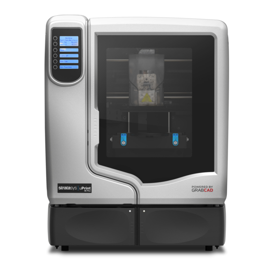
Page 29: Printer Overview
SE build a maximum part size of 203 x 152 x 152 mm (8 x 6 x 6 in). uPrint Plus and uPrint SE Plus build a maximum part size of 203 x 203 x 152 mm (8 x 8 x 6 in). Each uPrint and uPrint Plus material carrier contains 492 cc (30 cu. - Page 30 Figure 2-11: Interior chamber - front view Extrusion Head Tip wipe assembly Purge bucket Z stage platen Modeling base retainers (x2) Modeling base Z stage guide rods Z stage lead screw Extrusion Tips uPrint/uPrint SE Service Manual 2-19...
- Page 31 Figure 2-12: Rear view of printer Model Material Y Connector Support Material Tube Model Material Tube UPS Connection AC Power Cord Connector Material Bay Cable Connector Circuit Breaker RJ-45 Network Connector Material Bay Diagnostics Cable Connector Optional Model Material Tube Material Bay Communications Cable Optional Material Bay Optional Material Bay Communications Cable...
- Page 32 Figure 2-14: Modeling base Modeling base Caution: DO NOT reuse modeling bases. If a modeling base is reused, calibration errors, poor part quality, and loss of extrusion may occur. Additional modeling bases are available from your reseller. uPrint/uPrint SE Service Manual 2-21...
- Page 33 Figure 2-15: Startup Kit contents Gloves Power cord (Euro) Power cord (US) Crossover cable (orange) Network cable (blue) Tip replacement kit (A. Support tip B. Model tip C. 8 Tip shields D. 4 Tip wipe assemblies) 10x magnifier loupe Wire brush Cutters 1/8 inch T-Handle wrench (red) 7/64 inch T-Handle wrench (yellow)
-
Page 34: Finding More Information
CatalystEX Online Help Simple operating instructions for CatalystEX are available in CatalystEX Dynamic Help. You can also see CatalystEX Help from the menu bar - Help>Contents World Wide Web Additional information is available at: http://www.uprint3dprinting.com uPrint/uPrint SE Service Manual 2-23... - Page 35 2-24...
-
Page 36: Software
Gantry ____________________________________________________________ 3-9 Temperatures ____________________________________________________ 3-10 Outputs __________________________________________________________ 3-10 Table ____________________________________________________________ 3-10 Get Calibration___________________________________________________ 3-11 Send Calibration _________________________________________________ 3-11 Get Config _______________________________________________________ 3-11 Test Parts _________________________________________________________ 3-11 Reset Password___________________________________________________ 3-11 Connect _________________________________________________________ 3-12 Help _____________________________________________________________ 3-12 uPrint/uPrint SE Service Manual... -
Page 37: Software Architecture
Software Architecture Figure 3-16. shows the major software components that control the system. The software that runs on the Controller Board is EPROM based. The software that runs on the single board computer is stored on the HDD and loaded during power up. Like all PC compatible computers, the SBC runs a brief self-test on power up and then loads the operating system followed by the system’s application components. -
Page 38: System Manager
This software handles all non-motion control interactions between the SBC and the Controller Board. Events are printer status information being sent to the SBC. Commands come from the SBC telling the Controller Board to do something such as find home. uPrint/uPrint SE Service Manual... -
Page 39: Datastatex
DataStatEX DataStatEX is a “condensed” version of MaracaEX. It was developed to: • Aid in troubleshooting system problems by allowing the customer to view and report specific system information. • Allow the customer to adjust Z Tip to Tip (difference in tip heights) •... -
Page 40: Catalystex
CatalystEX Help in a separate window containing standard Help tools - TOC, Search, Index, and personally selected Favorites. Dynamic Help Dynamic Help is available from within the CatalystEX application window. The right side of the application window is dedicated to Dynamic Help. uPrint/uPrint SE Service Manual... -
Page 41: Maracaex Help
MaracaEX Help Overview MaracaEX is a program used for machine configuration and troubleshooting. It is intended for use by trained service personnel only. Caution: It is possible, using this program, to damage the controller software and make the machine non-functional. Using MaracaEX you can select a modeler to work with, modify machine-specific configuration parameters, download new calibration file data, download new test parts, and test the machine's operation. -
Page 42: Modeler Setup
The model liquefier temperature and its set point in C. Head PWM Not used. Support Temp The support liquefier temperature and its set point in C (SST only). Support PWM Not used. Chamber Temp The actual chamber temperature and its set point in C. uPrint/uPrint SE Service Manual... -
Page 43: Versions
Versions Product Version The current version number for the complete software release. Build Version The build number for current SBC software. Firmware Version The current version for the 186/Controller software. PLD Version The current version of the programmable logic devices on the 186 or Controller boards. Product serial number The serial number of the complete system. -
Page 44: Setting The Serial Number
P400R - is a standard release material. P400SR - is a standard soluble release material. Manufacturing Lot This is a lot code used by Stratasys to control the manufacturing process. Manufacturing Date This is the date that the cartridge was manufactured. -
Page 45: Part Calibration
Part Calibration Left Measured on left side of modeling base, front to back. Right Measured on right side of modeling base, front to back. Front Measured on front side of modeling base, left to right. Back Measured on back side of modeling base, left to right. Left Front Measured from front left corner to rear right corner. -
Page 46: Get Calibration
Reset Password This button resets the administrator password to null. This turns off password control of the queue. This is used for clearing a forgotten password. uPrint/uPrint SE Service Manual 3-11... -
Page 47: Connect
Connect If the system is not available over the network, when MaracaEX first loads, MaracaEX will only try to connect one time. This allows you to interact with MaracaEX when it is not connected to a machine. The Connect button allows you to request additional connection attempts. -
Page 48: Service Procedures
Service Procedures Maintenance Preparation ____________________________________________ 4-3 Required Tools list ____________________________________________________ 4-4 Distributer/Reseller supplied Tools ___________________________________ 4-4 Supplied by Stratasys ______________________________________________ 4-4 Pre-Maintenance Procedures _________________________________________ 4-4 Exterior Components _________________________________________________ 4-5 Top Panel _________________________________________________________ 4-5 Side Panels________________________________________________________ 4-7 Display Panel______________________________________________________ 4-9 Front Panel _______________________________________________________ 4-11... - Page 49 Toggle Sensor ____________________________________________________ 4-69 Toggle Bar _______________________________________________________ 4-71 Head Board______________________________________________________ 4-76 TC Amp board ___________________________________________________ 4-82 Umbilical Hose ___________________________________________________ 4-84 Material Tubes ___________________________________________________ 4-88 Umbilical Cable __________________________________________________ 4-89 XY Table Components _______________________________________________ 4-91 Y Home Sensor ___________________________________________________ 4-91 Y EOT (End of Travel) Sensor _______________________________________ 4-92 X Motor __________________________________________________________ 4-93 Y Motor _________________________________________________________ 4-100 Y Motor Belt _____________________________________________________ 4-103...
-
Page 50: Maintenance Preparation
Note: All references within this procedure to ‘Left’ or ‘Right’ are made assuming that the printer is being viewed from the ‘Front’ (the door and user interface panel side). uPrint/uPrint SE Service Manual... -
Page 51: Required Tools List
Nut driver set Dial indicator Serial data cable (for issuing TeraTerm commands) Supplied by Stratasys Belt tension gauge (for adjusting XY table drive belts) Y-Motor belt tensioning tool (for adjusting belt Y table motor belt) Head dial indicator bracket (for XY table and Z stage leveling) -
Page 52: Exterior Components
” nut driver or standard screwdriver, remove the 3 mounting screws. See Figure 4-17. Figure 4-17: Top panel mounting screw location Remove the 3 top panel mounting screws Lift up and slide the top panel towards the back of the printer to remove. See Figure 4-18. uPrint/uPrint SE Service Manual... - Page 53 Figure 4-18: Top panel removal Slide top panel toward the back of the printer and lift up to remove. Installing the top panel Slide the top panel towards the front and in to place, then push down. Using a ⁄ ”...
-
Page 54: Side Panels
Slide panel towards the back of the printer and pull outward to remove. See Figure 4-20. Figure 4-20: Removing the left side panel Slide top panel toward the back of the printer and pull outward to remove the left side panel. uPrint/uPrint SE Service Manual... - Page 55 Removing the right side panel Using a ⁄ ” nut driver or standard screwdriver, remove the 3 mounting screws. See Figure 4-21. Figure 4-21: Right side panel mounting screw locations Remove the 3 right side panel mounting screws. Slide towards the back of the printer and pull outward to remove. See Figure 4-22.
-
Page 56: Display Panel
Figure 4-23: Opening the display panel access hatch Reach behind the display panel and press the tab to release the display panel. See Figure 4-24. Figure 4-24: Removing the display Disconnect J1 connector. See Figure 4-25. uPrint/uPrint SE Service Manual... - Page 57 Figure 4-25: Disconnecting the J1 connector Remove the display panel. Installing the display panel Connect the J1 Connector. Gently push the display panel into place. Close the display panel access hatch. Close the chamber door. 4-10...
-
Page 58: Front Panel
Figure 4-26: Front panel mounting screw locations Remove the 2 mounting screws from behind the display panel Using a ⁄ ” nut driver or standard screwdriver, remove the 6 mounting screws from the front panel. See Figure 4-27. uPrint/uPrint SE Service Manual 4-11... - Page 59 Figure 4-27: Front panel mounting screw locations Remove the 6 mounting screws for the front panel Remove the front panel by pulling outward. Installing the front panel Align the front panel with the mounting holes. Using a ⁄ ” nut driver or standard screwdriver, reinstall the 6 mounting screws. Using a ⁄...
-
Page 60: Door Solenoid
Push the solenoid pin out and slide door solenoid into place on the mounting plate. Reconnect the DRSOL cable. Reinstall the front panel. See Installing the front panel on page 4-12. Reinstall the display panel. See Installing the display panel on page 4-10. uPrint/uPrint SE Service Manual 4-13... -
Page 61: Door Sensor
Door Sensor Required Tools • ⁄ ” nut driver or standard screwdriver. Removing the door sensor Remove the display panel. See Removing the display panel on page 4-9. Remove the front panel. See Removing the front panel on page 4-11. Disconnect the DRSW cable. See Figure 4-30. -
Page 62: Electronics Bay Components
Figure 4-32: Removing the filament tubes from the Y connectors Using a ⁄ ” nut driver or standard screwdriver, remove the 3 mounting screws on the top of the electronics bay cover. See Figure 4-33. uPrint/uPrint SE Service Manual 4-15... - Page 63 Figure 4-33: Electronics bay cover mounting screw locations Remove the 3 mounting screws Gently pull the electronics bay cover down. See Figure 4-34. Figure 4-34: Electronics bay with cover lowered Closing the electronics bay Gently push the electronics bay cover back in to the closed position. Using a ⁄...
-
Page 64: Upper Electronics Bay Cover
Figure 4-35: Upper electronics bay cover top mounting screw locations Loosen but do not remove the 2 mounting screws Using a ⁄ ” nut driver or standard screwdriver, remove the bottom left and right mounting screws. See Figure 4-36. uPrint/uPrint SE Service Manual 4-17... - Page 65 Figure 4-36: Upper electronics bay cover bottom mounting screw locations Remove the bottom left and right mounting screws Lift the cover up and off of the top mounting screws. Installing the upper electronics bay cover Slide the cover down on to the top left and right side mounting screws. Using a ⁄...
-
Page 66: Removing The Electronics Bay
Figure 4-37: I/O card cable locations I/O Card cable Chamber thermocouple locations wire location Remove the left and right side electronics bay mounting screws with a ⁄ ” nut driver or standard screwdriver. See Figure 4-38. uPrint/uPrint SE Service Manual 4-19... - Page 67 Figure 4-38: Electronics Bay mounting screw locations Remove the 4 left side Remove the 4 right mounting screws side mounting screws Slide the electronics bay out 3 inches (76mm) and disconnect the cables from the rear of the power distribution board. See Figure 4-39.
-
Page 68: Electronics Bay Cooling Fan
Touch the metal plate of the electronics bay cover to discharge any static electricity. Disconnect the P1 cable from the fan. See Figure 4-40. Figure 4-40: Electronics bay cooling fan connector location P1 Connector Using a ⁄ ” allen wrench, remove the 4 mounting screws. See Figure 4-41. uPrint/uPrint SE Service Manual 4-21... - Page 69 Figure 4-41: Electronics bay cooling fan mounting screw locations Remove the 4 mounting screws Remove the cooling fan. Installing the electronics bay cooling fan Align the cooling fan with the 4 mounting holes. Using a ⁄ ” allen wrench, reinstall the 4 mounting screws. Reconnect the P1 cable.
-
Page 70: Controller Board
Figure 4-42: Controller board ribbon cable locations Remove the 3 ribbon cables Using a standard screwdriver, loosen the 2 screws that hold the diagnostics DB-9 cable in place. Then gently pull the cable out of the connector. See Figure 4-43. uPrint/uPrint SE Service Manual 4-23... - Page 71 Figure 4-43: Remove the 2 screws that hold the Diagnostics DB-9 cable in place Remove the DB-9 connector Using a Phillips screwdriver, remove the 6 controller board mounting screws. See Figure 4-44. Figure 4-44: Controller board mounting screw locations Remove the (6) mounting screws Gently lift the controller board up from the single board computer (SBC) at the P104 connector.
- Page 72 Insert the printer firmware CD into the workstation CD drive. From the Printer Services tab, click on the Update Software button. Navigate CatalystEX to the Upgrade (.UPG) file on the printer firmware CD. The printer will load, reboot and verify the upgrade. uPrint/uPrint SE Service Manual 4-25...
-
Page 73: Single Board Computer (Sbc)
Single Board Computer (SBC) Required Tools • ⁄ ” nut driver or standard screwdriver. • Phillips screwdriver Hardware • 6-32 x ⁄ ” Phillips pan head screws (x4) Removing the single board computer Open the electronics bay. See Opening the electronics bay on page 4-15. Touch the metal plate of the electronics bay cover to discharge any static electricity. - Page 74 Remove the 4 mounting screws Lift the SBC and disconnect the IDE ribbon cable by pulling out of the socket. See Figure 4-49. Figure 4-49: SBC IDE ribbon cable location Disconnect the IDE ribbon cable uPrint/uPrint SE Service Manual 4-27...
- Page 75 Using a standard screwdriver, loosen the display cable mounting screws. See Figure 4- Disconnect the display cable from the SBC. See Figure 4-50. Figure 4-50: SBC display cable location Disconnect the Display cable Installing the single board computer Reconnect the display cable. Using a standard screwdriver, tighten the display cable mounting screws.
-
Page 76: Power Distribution I/O Card
Figure 4-51: I/O card cable locations Disconnect all 6 of the cables Disconnect the thermocouple from the back side of the I/O card by pulling outward. See Figure 4-52. Figure 4-52: Chamber thermocouple wire location Disconnect the chamber thermocouple uPrint/uPrint SE Service Manual 4-29... - Page 77 Using a Phillips screwdriver, remove the 3 mounting screws from the I/O card. See Figure 4-53. Figure 4-53: I/O card mounting screw locations Remove the 3 mounting screws Gently pull the I/O card out from the power distribution board sockets. Installing the I/O card Gently slide the I/O card in to the power distribution board sockets.
-
Page 78: Power Distribution Board (Pdb)
3 inches (76mm). See Figure 4-55. Figure 4-55: Electronics bay mounting screw locations Remove the 4 left Remove the 4 right side mounting screws side mounting screws uPrint/uPrint SE Service Manual 4-31... - Page 79 Disconnect the 4 cables from the back side of the power distribution board. See Figure 4- Figure 4-56: Power distribution board rear cable locations Disconnect the 4 cables on the back of the Slide the Electronics Bay back into place. Disconnect the 10 cables from the front of the PDB.
- Page 80 Installing the I/O card on page 4-30. Close the electronics bay. See Closing the electronics bay on page 4-16. Reinstall the side panels. See Installing the side panels on page 4-8. Reinstall the top panel. See Installing the top panel on page 4-6. uPrint/uPrint SE Service Manual 4-33...
-
Page 81: Hard Drive
Hard Drive Required Tools • ⁄ ” nut driver or standard screwdriver. • Phillips screwdriver Hardware • 6-32 x ⁄ ” Phillips pan head screws (x8) Removing the SATA Hard Drive Open the electronics bay. See Opening the electronics bay on page 4-15. Touch the metal plate of the electronics bay cover to discharge any static electricity. - Page 82 Slide the hard drive up and out of the electronics bay. Using a Phillips screwdriver, remove the mounting brackets from the hard drive. See Figure 4-62. Figure 4-62: Hard drive mounting bracket screw locations Remove mounting brackets uPrint/uPrint SE Service Manual 4-35...
- Page 83 Installing the SATA hard drive Using a Phillips screwdriver, reinstall the 2 mounting brackets. Push the hard drive in the slots and down into position. Using a Phillips screwdriver, reinstall the 4 mounting screws. Reconnect the SATA cable. Reconnect the power input cable. Close the electronics bay.
- Page 84 Disconnect the SATA cable by pressing the metal tab in and pulling down. See Figure 4- Figure 4-64: IDE cable location Disconnect the IDE ribbon cable Using a Phillips screwdriver, remove the 4 mounting screws. See Figure 4-61. uPrint/uPrint SE Service Manual 4-37...
- Page 85 Figure 4-65: Hard drive mounting screw locations Remove the mounting Remove the mounting screws screws Slide the hard drive up and out of the electronics bay. Using a Phillips screwdriver, remove the mounting brackets from the hard drive. See Figure 4-62. Figure 4-66: Hard drive mounting bracket screw locations Remove mounting brackets...
- Page 86 Cycle power on the printer. Replace the CD into the electronics bay. Perform Offset calibrations, see Offset Calibrations on page 5-2. Perform Part Based calibration, see Part Based Calibration on page 5-7. uPrint/uPrint SE Service Manual 4-39...
-
Page 87: Line Filter
Line Filter Required Tools • ⁄ ” nut driver or standard screwdriver. • Phillips screwdriver Hardware • 6-32 x ⁄ ” Phillips pan head screws (x3) Removing the line filter Open the electronics bay. See Opening the electronics bay on page 4-15. Touch the metal plate of the electronics bay cover to discharge any static electricity. - Page 88 Reconnect the L2-1 and N2-1 spade connectors to the left side of the board. Reconnect the LF2-P and LF2-N spade connectors to the right side of the board. Close the electronics bay. See Closing the electronics bay on page 4-16. uPrint/uPrint SE Service Manual 4-41...
-
Page 89: Circuit Breaker
Circuit Breaker Required Tools • ⁄ ” nut driver or standard screwdriver. • Phillips screwdriver Removing the circuit breaker Open the electronics bay. See Opening the electronics bay on page 4-15. Touch the metal plate of the electronics bay cover to discharge any static electricity. Remove the Load and CB1 spade connectors from the circuit breaker by pulling up on the connectors. - Page 90 Push the circuit breaker through the electronics bay panel until it locks in place. Reconnect the CB1 and CB2 spade connectors to the circuit breaker. Reconnect the Load and CB1 spade connectors to the circuit breaker. Close the electronics bay. See Closing the electronics bay on page 4-16. uPrint/uPrint SE Service Manual 4-43...
-
Page 91: Ac Input
AC Input Required Tools • ⁄ ” nut driver or standard screwdriver. • Phillips screwdriver Hardware • ⁄ ” x 6mm Phillips pan head screws (x2) Removing the AC Input Open the electronics bay. See Opening the electronics bay on page 4-15. Touch the metal plate of the electronics bay cover to discharge any static electricity. - Page 92 Install the 2 AC Input mounting screws with a Phillips screwdriver. 2. Connect the LF-P (black) spade connector. 3. Connect the LF-N (white) spade connector. 4. Connect the LF-G (green) spade connector. 5. Close the electronics bay. See Closing the electronics bay on page 4-16. uPrint/uPrint SE Service Manual 4-45...
-
Page 93: Power Switch
Power Switch Required Tools • ⁄ ” nut driver or standard screwdriver. Hardware • 10-32 x ⁄ ” slotted screws (x2) Removing the Power Switch Remove the top panel. See Removing the top panel on page 4-5. Remove the left side panel. See Side Panels on page 4-7. - Page 94 ⁄ ” nut driver or standard screwdriver, reinstall the 2 mounting screws. Reinstall the left side panel. See Installing the side panels on page 4-8. Install the top panel. See Installing the top panel on page 4-6. uPrint/uPrint SE Service Manual 4-47...
-
Page 95: 24Vdc Power Supply
24VDC Power Supply Required Tools • ⁄ ” nut driver or standard screwdriver. • Phillips screwdriver Hardware • 10-32 x ⁄ ” slotted screws (x3) • 6-32 x ⁄ ” Phillips pan head screws (x2) Removing the 24VDC Power Supply Remove the top panel. - Page 96 Figure 4-81: Closing the rear panel of the electronics bay Remove the 2 mounting screws Open the rear panel of the electronics bay and remove the 2 board mounting screws from the top of the panel using a Phillips screwdriver. See Figure 4-82. uPrint/uPrint SE Service Manual 4-49...
- Page 97 Figure 4-82: Removing the 2 mounting screws from the top of the panel Remove the 2 mounting screws Remove the 24VDC power supply. Installing the 24VDC power supply Align the 24VDC power supply with the top of the rear panel of the electronics bay and the tab to the right of the mounting location.
-
Page 98: 5/12Vdc Power Supply
Open the rear panel of the electronics bay. Touch the metal plate of the electronics bay cover to discharge any static electricity. Disconnect the J2 spade connector by lifting up on the connector. See Figure 4-85. uPrint/uPrint SE Service Manual 4-51... - Page 99 Figure 4-85: J2 spade connector location Disconnect the SK2 connector by pressing the tab and lifting up on the connector. See Figure 4-86. Figure 4-86: SK2 connector location Disconnect the power input cable by pressing the tab and lifting up on the connector. See Figure 4-87.
- Page 100 Reinstall the electronics bay. See Installing the electronics bay on page 4-20. Reinstall the side panels. See Installing the side panels on page 4-8. Reinstall the top panel. See Installing the top panel on page 4-6. uPrint/uPrint SE Service Manual 4-53...
-
Page 101: 120Vdc Power Supply
120VDC Power Supply Required Tools • ⁄ ” nut driver or standard screwdriver. • Phillips screwdriver Hardware • 10-32 x ⁄ ” slotted screws (x3) • 6-32 x ⁄ ” Phillips pan head screws (x3) Removing the 120VDC power supply Remove the top panel. - Page 102 Reinstall the electronics bay. See Installing the electronics bay on page 4-20. Reinstall the side panels. See Installing the side panels on page 4-8. Reinstall the top panel. See Installing the top panel on page 4-6. uPrint/uPrint SE Service Manual 4-55...
-
Page 103: Head Components
Head Components Head Cooling Fan Required Tools • ⁄ ” nut driver or standard screwdriver. • ⁄ ” allen wrench. Hardware • 6-32 x 1 ⁄ ” flat head cap screws (x2) Removing the head cooling fan Remove the top panel. See Removing the top panel on page 4-5. - Page 104 Install the upper electronics bay cover. See Installing the upper electronics bay cover on page 4-18. Install the side panels. See Installing the side panels on page 4-8. Install the top panel. See Installing the top panel on page 4-6. uPrint/uPrint SE Service Manual 4-57...
-
Page 105: Toggle Head Assembly
Toggle Head Assembly Required Tools • ⁄ ” nut driver or standard screwdriver. • Cutters Hardware • Wire tie (x1) • 10-32 x ⁄ ” slotted screws (x7) • 10-32 x ⁄ ” slotted screws (x4) Removing the toggle head assembly Remove the top panel. - Page 106 Press in tab Press in tab to release air to release air plenum plenum Disconnect the material tubes by pressing down on the retaining ring and lifting up the material tubes. See Figure 4-97. uPrint/uPrint SE Service Manual 4-59...
- Page 107 Figure 4-97: Material tubes and retaining rings Press down Lift the on the material retaining tubes out of rings the rings Disconnect the thermocouples from the TC Amp board and remove the wires from the wire retainer. See Figure 4-98 Figure 4-99.
- Page 108 Disconnect the toggle sensor cable from the head board. See Figure 4-102. Figure 4-102: Toggle sensor cable location Disconnect the toggle sensor cable from the head board Cut the wire tie holding the drive motor cables in place. See Figure 4-103. uPrint/uPrint SE Service Manual 4-61...
- Page 109 Figure 4-103: Wire tie location Cut and remove the wire tie from the head motor Disconnect the 3 cables from the rear of the head board by pressing the tabs in and pulling outward. See Figure 4-104. Figure 4-104: Rear head board cable locations Disconnect the 3 cables Using a...
- Page 110 Z Tip to Tip field in the Tip Offset window. Click on the green check mark button. Cycle power to the printer. From the display panel press Maintenance > Machine > Tips Perform Z calibration. Perform XY Offset calibration. uPrint/uPrint SE Service Manual 4-63...
-
Page 111: Substrate Sensor
Substrate Sensor Required Tools • ⁄ ” nut driver or standard screwdriver. • ⁄ ” allen wrench. Hardware • Wire tie (x1) • 10-32 x ⁄ ” slotted screws (x7) • 4-40 x ⁄ ” slotted screws and # 4 split lock washer (x4) Removing the substrate sensor Remove the top panel. - Page 112 Using a ⁄ ” allen wrench, remove the 4 substrate sensor mounting screws. See Figure 4- 110. Figure 4-110: Substrate sensor mounting screw locations Remove the 4 mounting screws Remove the substrate sensor. uPrint/uPrint SE Service Manual 4-65...
- Page 113 Installing the substrate sensor Align the substrate sensor with the mounting holes. Using a ⁄ ” allen wrench, reinstall the 4 substrate sensor mounting screws. Reconnect the substrate sensor wire to the head board. Reinstall the wire tie around the head motor and wires. See Figure 4-111.
-
Page 114: Z Foam Level Assembly
Push the Z foam level assembly actuator up into the assembly and slide the Z foam level bar to the right until it is clear of the assembly. See Figure 4-112. Figure 4-112: Removing the Z foam level bar uPrint/uPrint SE Service Manual 4-67... - Page 115 Using a ⁄ ” allen wrench, remove the 4 Z foam level assembly mounting screws and washers. See Figure 4-113. Note: Be careful not to lose the washers. Figure 4-113: Z foam level assembly mounting screw locations 4 mounting screws Remove the Z foam level assembly and discard.
-
Page 116: Toggle Sensor
Figure 4-114: Right side access panel mounting screw locations Remove the 7 mounting screws. Gently disconnect the toggle sensor wire by pulling outwards. See Figure 4-115. Figure 4-115: Toggle sensor wire connector location Gently disconnect the toggle sensor cable uPrint/uPrint SE Service Manual 4-69... - Page 117 Using a standard screwdriver, remove the 2 toggle sensor mounting screws. See Figure 4-116. Figure 4-116: Toggle sensor mounting screw locations Remove the 2 mounting screws Remove the toggle sensor. Installing the toggle sensor Align the toggle sensor with the mounting holes. Using a standard screwdriver, reinstall the 2 mounting screws.
-
Page 118: Toggle Bar
• .141” ID, .625” OD x .031” Washer • 8mm ID, 18mm OD x 1mm Washer • .195” ID, .50” OD x .059” PEEK HPV Washer (x2) Removing the toggle bar Unload model and support material. Power the printer down. uPrint/uPrint SE Service Manual 4-71... - Page 119 Open chamber door and remove the head cover. See Figure 4-117. Figure 4-117: Head cover tab locations Press tab in to Press tab in to release head release head cover cover Using a ⁄ ” allen wrench, loosen but do not remove the 4 tip mounting screws. See Figure 4-118.
- Page 120 ” allen wrench, remove the upper spring screw. Remove the screw, washer and spring. See Figure 4-121. Figure 4-121: Upper spring location Upper spring screw Using a ⁄ ” allen wrench, remove the lower spring screw. Remove the screw, spring and washer. See Figure 4-122. uPrint/uPrint SE Service Manual 4-73...
- Page 121 Figure 4-122: Lower spring location Lower spring screw Pull the toggle assembly away from the translator until the toggle assembly is at the end of the post. See Figure 4-123. Figure 4-123: Toggle assembly positioning Remove the washer from the toggle bar. Remove the toggle bar by sliding out.
- Page 122 Reinstall the model tip (right side) and support tip (left side) by pushing up into place. Using a ⁄ ” allen wrench tighten the tip mounting screws. Reinstall the head cover. Power the printer up. Perform calibrations. See Offset Calibrations on page 5-2. uPrint/uPrint SE Service Manual 4-75...
-
Page 123: Head Board
Head Board Required tools • ⁄ ” nut driver or standard screwdriver • ⁄ ” nut driver Hardware • 10-32 x ⁄ ” slotted screws (x7) • 6-32 x ⁄ ” slotted screws (x6) Removing the head board Remove the top panel. See Removing the top panel on page 4-5. - Page 124 Figure 4-129: Material tube and retaining ring locations Press down on Lift the the retaining material rings tubes out of the rings Remove the thermocouple wires from the wire retaining clip on the head board. See Figure 4-130. uPrint/uPrint SE Service Manual 4-77...
- Page 125 Figure 4-130: Retaining clip location Remove the thermocouple wires from the retaining clip Disconnect the umbilical cable by pressing in on the tab and pulling upwards. See Figure 4-131. Figure 4-131: Umbilical cable location Disconnect the umbilical cable Disconnect the model and support heater cables by pressing in on the tabs and pulling outward.
- Page 126 ” nut driver or standard screwdriver, remove the toggle sensor cable retaining clips. See Figure 4-135. Figure 4-135: Toggle sensor cable retaining clip locations Remove the 2 toggle sensor cable retaining clips Feed the toggle sensor cable out through the head board. See Figure 4-136. uPrint/uPrint SE Service Manual 4-79...
- Page 127 Figure 4-136: Removing the toggle sensor cable from the head board Feed toggle sensor cable through the head board Disconnect the substrate sensor cable and filament motor cables from the rear of the head board by pressing the tabs in and pulling outward. See Figure 4-137.
- Page 128 Reinstall the air plenum. Reinstall the head cover. Reinstall the right side access cover. Reinstall the side panels. See Installing the side panels on page 4-8. Reinstall the top panel. See Installing the top panel on page 4-6. uPrint/uPrint SE Service Manual 4-81...
-
Page 129: Tc Amp Board
TC Amp board Required Tools • ⁄ ” nut driver or standard screwdriver • ⁄ ” nut driver Hardware • 10-32 x ⁄ ” slotted screws (x7) • 6-32 x ⁄ ” slotted screws (x3) Removing the TC Amp board Remove the top panel. - Page 130 Reconnect the model and support thermocouple wires. Reconnect the umbilical cable. Reinstall the right side access panel. Reinstall the side panels. See Installing the side panels on page 4-8. Reinstall the top panel. See Installing the top panel on page 4-6. uPrint/uPrint SE Service Manual 4-83...
-
Page 131: Umbilical Hose
Umbilical Hose Required Tools • ⁄ ” nut driver or standard screwdriver • ⁄ ” nut driver • ⁄ ” allen wrench • Cutters Hardware • Wire tie • 10-32 x ⁄ ” slotted screws (x7) • ⁄ - 20 x ⁄... - Page 132 Press in tab to Press in tab to release air plenum release air plenum Press in tab to Press in tab to release air plenum release air plenum Disconnect the model and support material tubes. See Figure 4-147. uPrint/uPrint SE Service Manual 4-85...
- Page 133 Figure 4-147: Material tube and retaining ring locations Press down on Lift the material the retaining tubes out of the rings rings Cut the wire tie from around the umbilical hose. See Figure 4-148. Figure 4-148: Umbilical hose wire tie location Cut and remove the wire tie Remove the energy chain mounting screws from the translator with a...
- Page 134 Reinstall the upper electronics bay cover. See Installing the upper electronics bay cover on page 4-18. Reinstall the side panels. See Installing the side panels on page 4-8. Reinstall the top panel. See Installing the top panel on page 4-6. uPrint/uPrint SE Service Manual 4-87...
-
Page 135: Material Tubes
Material Tubes Required Tools • ⁄ ” nut driver or standard screwdriver • ⁄ ” nut driver • ⁄ ” allen wrench • Cutters Removing the material tubes Remove the top panel. See Removing the top panel on page 4-5. Remove the side panels. See Side Panels on page 4-7. -
Page 136: Umbilical Cable
I/O card Disconnect the umbilical cable from the head board by pressing in on the tab and pulling upward. See Figure 4-152. Figure 4-152: Head board connector location Disconnect the umbilical cable uPrint/uPrint SE Service Manual 4-89... - Page 137 Disconnect the umbilical cable from the TC Amp board by pressing in on the tab and pulling outward. See Figure 4-153. Figure 4-153: TC Amp connector location Disconnect the umbilical cable Feed the umbilical cable out through the energy chain. Installing the umbilical cable Feed the umbilical cable through the energy chain.
-
Page 138: Xy Table Components
Align the Y Home Sensor with the mounting hole. 2. Using a ⁄ ” nut driver or standard screwdriver, reinstall the mounting screw. 3. Reconnect the Y Home cable. 4. Install the top panel. See Installing the top panel on page 4-6. uPrint/uPrint SE Service Manual 4-91... -
Page 139: Y Eot (End Of Travel) Sensor
Y EOT (End of Travel) Sensor Required Tools • ⁄ ” nut driver or standard screwdriver. Hardware • 6-32 x ⁄ ” slotted screw (x1) Removing the Y EOT sensor Remove the top panel. See Removing the top panel on page 4-5. Disconnect the Y EOT cable by pressing in on the tab and pulling outward. -
Page 140: Motor
Remove the side panels. See Side Panels on page 4-7. Using a ⁄ ” nut driver or standard screwdriver, remove the 7 left side access panel mounting screws and remove the left side access panel. See Figure 4-158. uPrint/uPrint SE Service Manual 4-93... - Page 141 Figure 4-158: Left side access panel mounting screw locations Remove the 7 mounting screws. Using a ⁄ ” nut driver or standard screwdriver, remove the 7 right side access panel mounting screws and remove the right side access panel. See Figure 4-159.
- Page 142 Figure 4-162. Figure 4-162: X motor cable connector location Disconnect X motor cable Using a ⁄ ” nut driver or standard screwdriver, remove the 2 X energy chain mounting bracket mounting screws. See Figure 4-163. uPrint/uPrint SE Service Manual 4-95...
- Page 143 Figure 4-163: X motor energy chain mounting bracket mounting screw locations Remove the 2 mounting screws Using a ⁄ ” nut driver or standard screwdriver, remove the 4 mounting screws from the X motor mounting bracket. See Figure 4-164. Figure 4-164: X motor mounting bracket mounting screw locations Remove the 4 mounting screws Using a...
- Page 144 ‘zero’ reading: The large hand should be on 0 and the small hand on 5. Tighten the adjustment screw (do not over tighten the screw) and recheck the reading. Remove the zero block gauge block from the fixture. uPrint/uPrint SE Service Manual 4-97...
- Page 145 Figure 4-167: Tension gauge zero setting Adjustment screw Zero gauge block Position the dial indicator on the rear section of the X-Drive belt - centered between the Head Assembly and the left side of the build envelope. See Figure 4-168. Figure 4-168: X belt tension location Check the tension: The large hand on the gauge should read between 25 and 35 mils, and the small hand...
- Page 146 Figure 4-170: X-Drive Belt Tension Adjustment X belt tension bolt Remove the belt fixture and run the head back and forth several times. Continue to adjust and check the tension until the tension meets specification. uPrint/uPrint SE Service Manual 4-99...
-
Page 147: Y Motor
Y Motor Required Tools • ⁄ ” nut driver or standard screwdriver. • ⁄ ” allen wrench. Hardware • 10-32 x ⁄ ” slotted screws (x11) • 8-32 x ⁄ ” socket head cap screws (x4) Removing the Y motor Remove the top panel. - Page 148 See Figure 4-173. Figure 4-173: Y motor mounting bracket mounting screw locations Remove the 4 mounting screws Using a ⁄ ” allen wrench, remove the 4 Y motor mounting screws. See Figure 4-174. uPrint/uPrint SE Service Manual 4-101...
- Page 149 Figure 4-174: Y motor mounting screw locations Remove the 4 mounting screws Remove the Y motor. Installing the Y motor Align the Y motor with the Y motor mounting bracket, making sure the Y motor cable faces the back of the printer. Using a ⁄...
-
Page 150: Y Motor Belt
Remove the upper electronics bay cover. See Removing the upper electronics bay cover on page 4-17. Remove the left side access panel. See Figure 4-175. Figure 4-175: Left side access panel mounting screw locations Remove the 7 mounting screws. uPrint/uPrint SE Service Manual 4-103... - Page 151 Disconnect the material bay cable from the printer. Remove the Front Panel. See Removing the front panel on page 4-11. Remove the Electronics Bay. See Removing the electronics bay on page 4-19. Using a ⁄ ” nut driver or standard screwdriver, remove the right side access panel mounting screws and remove the right side access panel.
- Page 152 Disconnect the head cooling fan. See Figure 4-180. Figure 4-180: Disconnect head cooling fan J258 Disconnect J258 Using a ⁄ ” nut driver or standard screwdriver, remove the head cooling fan mounting bracket screws. See Figure 4-181. uPrint/uPrint SE Service Manual 4-105...
- Page 153 Figure 4-181: Head cooling fan mounting bracket screw locations Let head cooling fan hang off to side. Using a ⁄ ” nut driver or standard screwdriver, remove the 4 foam insert retaining screws and washers. See Figure 4-182. Figure 4-182: Foam insert retaining screw locations Remove the foam insert.
- Page 154 Figure 4-184. Figure 4-184: Y motor belt location Locate the 2 lower Y drive rod mounting screws. See Figure 4-185. Figure 4-185: Lower Y drive rod mounting screw locations Lower Y drive rod mounting screw locations uPrint/uPrint SE Service Manual 4-107...
- Page 155 Using a ⁄ ” nut driver or standard screwdriver, remove the 2 Y drive rod mounting screws. See Figure 4-186. Figure 4-186: Y drive rod mounting screws Right side mounting screw Left side mounting screw Locate and remove the 4 upper Y drive rod mounting screws with a ⁄...
- Page 156 Installing the front panel on page 4-12. Reinstall the Side panels. See Installing the side panels on page 4-8. Reinstall the top panel. See Installing the top panel on page 4-6. Reconnect the material bay cable, network cable and power cable. uPrint/uPrint SE Service Manual 4-109...
-
Page 157: Y Drive Rod
Y Drive Rod Required Tools • ⁄ ” nut driver or standard screwdriver. • Dial indicator and belt tension gauge assembly Hardware • 10-32 x ⁄ ” slotted screws (x30) • 3-16 x 1” fender washer Removing the Y Drive Rod Remove the top panel. - Page 158 ⁄ ” box wrench, loosen, but do not remove, the inner Y belt retaining clip mounting screws from the right side. See Figure 4-192. Pull the right side Y belt out from the retaining clip. uPrint/uPrint SE Service Manual 4-111...
- Page 159 Figure 4-192: Right side Y belt retaining clip mounting screw locations Remove the outer mounting screws Loosen, but do not remove the inner mounting screws Decrease the Y belt tension by turning the tensioning nut. See Figure 4-193. Figure 4-193: Y drive belt tension adjustment Y-Drive Belt Tension Adjusting Nut...
- Page 160 Figure 4-196: Foam insert retaining screw locations Remove the foam insert. Using a ⁄ ” nut driver or standard screwdriver, loosen but do not remove the 4 Y motor mounting bracket mounting screws. See Figure 4-197. uPrint/uPrint SE Service Manual 4-113...
- Page 161 Figure 4-197: Y motor mounting bracket screw locations Remove the Y motor belt from the Y motor pulley. See Figure 4-198. Figure 4-198: Y motor belt location Locate the 2 lower Y drive rod mounting screws. See Figure 4-199. Figure 4-199: Lower Y drive rod mounting screw locations Lower Y drive rod mounting screw locations 4-114...
- Page 162 See Figure 4-201. Figure 4-201: Upper Y drive rod mounting screw locations Lift the Y drive rod, slide out through the Y belts and discard. See Figure 4-202. Figure 4-202: Remove Y drive rod uPrint/uPrint SE Service Manual 4-115...
- Page 163 Installing the Y Drive Rod Slide the Y drive rod through the Y belts and into position. Align Y drive rod with the 6 mounting holes. Using a ⁄ ” nut driver or standard screwdriver, reinstall the 6 Y drive rod mounting screws.
-
Page 164: Xy Table
” allen wrench. • ⁄ ” allen wrench. • Cutters. • Z Guide rod stand off (x2) • Head bracket, dial indicator and belt tension gauge assembly • Y rod spacer (x2) • Leveling wrench uPrint/uPrint SE Service Manual 4-117... - Page 165 Hardware • Wire tie • 10-32 x ⁄ ” slotted screws (x14) • 10-32 x ⁄ ” slotted screws (x4) • 10-32 x ⁄ ” socket head cap screws (x4) • 8-32 x ⁄ ” socket head cap screws (x4) •...
- Page 166 Figure 4-205: Umbilical hose wire tie location Cut and remove the wire tie Using a ⁄ ” allen wrench, remove the 2 energy chain mounting screws. See Figure 4-206. Figure 4-206: Energy chain mounting screw locations Remove the 2 mounting screws uPrint/uPrint SE Service Manual 4-119...
- Page 167 Remove the substrate sensor. See Removing the substrate sensor on page 4-64. Using a ⁄ ” box wrench, remove the X belt tension adjuster by loosening the inside nut and then backing the bolt out of the mount. See Figure 4-207. Remove the tensioning fork and pulley from the X motor belt.
- Page 168 ⁄ ” box wrench, loosen, but do not remove, the inner Y belt retaining clip mounting screws from the right side. See Figure 4-212. Pull the right side Y belt out from the retaining clip. uPrint/uPrint SE Service Manual 4-121...
- Page 169 Figure 4-212: Right side Y belt retaining clip mounting screw locations Remove the outer mounting screws Loosen, but do not remove the inner mounting screws Move the translator to the rear of the printer. Using a ⁄ ” nut driver, remove the right side X guide rod mounting screws. See Figure 4-213.
- Page 170 Figure 4-217: Left side front Y guide rod mounting screw location Remove the left front Y guide rod mounting screw Using a ⁄ ” allen wrench, remove the left side rear Y guide rod mounting screw. See Figure 4-218. uPrint/uPrint SE Service Manual 4-123...
- Page 171 Figure 4-218: Left side rear Y guide rod mounting screw location Remove the left rear Y guide rod mounting screw Lift the front of the left Y guide rod upward until it is near the top of the frame. Rotate the left side Y guide rod towards the center of the printer and lower the guide rod. Pull the left side Y guide rod out towards the door opening.
- Page 172 Figure 4-220. Adjust (increase/decrease) the tension by turning the tensioning nut (Figure 4-222.) so that the dial indicator reads between 0.425 and 0.435 mils. Figure 4-222: Y drive belt tension adjustment Y-Drive Belt Tension Adjusting Nut uPrint/uPrint SE Service Manual 4-125...
- Page 173 Remove the belt fixture and move the belt forward and back several times. Reattach the belt tension gauge and recheck the tension. Continue to adjust and check the tension until the tension meets specification. Push the left side Y guide rod in towards the back of the printer. Rotate the left side Y guide rod towards the left side of the printer and raise the guide rod to the top of the frame.
- Page 174 Move 1 alignment bracket to the front of the printer. See Figure 4-225. Move the translator to the center of the XY table. Move 1 alignment bracket to the rear of the printer. See Figure 4-225. uPrint/uPrint SE Service Manual 4-127...
- Page 175 Figure 4-225: XY Table alignment bracket mounting locations Place an alignment Place an alignment bracket at the front bracket at the back of the printer of the printer Using a ⁄ ” nut driver or standard screwdriver, loosen but do not remove the left side X guide rod mounting screws.
- Page 176 Using a black marker or pen, mark the 4 corners of the Z stage. See Figure 4-228. Figure 4-228: Marking the 4 corners of the Z stage Mark the 4 corners of the Z stage Attach the XY leveling bracket and dial indicator to the head. See Figure 4-229. uPrint/uPrint SE Service Manual 4-129...
- Page 177 Move the dial indicator to the back right corner and write down the value. Enter the values that are written down into the XY level worksheet. Use the 8x6 worksheet for uPrint and uPrint SE, see Figure 4-230. Use the 8x8 worksheet for uPrint Plus and uPrint SE Plus, see Figure 4-231.
- Page 178 Figure 4-230: uPrint and uPrint SE measurement points and worksheet uPrint/uPrint SE Service Manual 4-131...
- Page 179 Figure 4-231: uPrint Plus and uPrint SE Plus measurement points and worksheet 4-132...
- Page 180 Loosen the adjustment screw and insert the dial indicator into the fixture. Adjust the depth of the dial indicator so the gauge reads 0.500 mils and tighten the adjustment screw. Recheck the reading. Remove the zero block gauge block from the fixture. uPrint/uPrint SE Service Manual 4-133...
- Page 181 Figure 4-233: Tension gauge zero setting Adjustment screw Zero gauge block Position the dial indicator on the rear section of the X-Drive belt - centered between the Head Assembly and the left side of the build envelope. See Figure 4-234. Figure 4-234: X belt tension location Check the tension: The gauge should read between 0.425 and 0.435 mils.
- Page 182 Remove the belt fixture and run the head back and forth several times. Continue to adjust and check the tension until the tension meets specification. Repeat steps 68 - 71 to zero the dial indicator. Reinstall a wire tie around the umbilical hose. See Figure 4-237. uPrint/uPrint SE Service Manual 4-135...
- Page 183 Perform XY Offset calibration. See XY Tip Calibration on page 5-5. Perform Part Based calibration. See Performing part based calibration for uPrint, uPrint SE, uPrint Plus and uPrint SE Plus from the Service Calibration menu (Firmware version 9.1 or newer) on page 5-7. 4-136...
-
Page 184: Z Stage Components
Installing the Z home sensor Align the Z home sensor with the mounting hole. Reinstall the mounting screw with a 1/4” nut driver or standard screwdriver. Reconnect the Z home cable. Close the chamber door. uPrint/uPrint SE Service Manual 4-137... -
Page 185: Z Eot (End Of Travel) Sensor
Z EOT (End of Travel) Sensor Required Tools • ⁄ ” nut driver or standard screwdriver. Hardware • 6-32 x ⁄ ” slotted screw (x1) Removing the Z EOT sensor Open the chamber door. Raise the Z stage all of the way up. Disconnect the Z EOT sensor cable by pressing in on the tab and pulling outward. -
Page 186: Chamber Fans
Remove the 4 mounting screws Using a ⁄ ” box wrench, remove the 2 chamber fan mounting screws. See Figure 4-243. Figure 4-243: Right side chamber fan mounting screw locations Remove the 2 mounting screws uPrint/uPrint SE Service Manual 4-139... - Page 187 Installing the right side chamber fan Align chamber fan with mounting holes. Using a ⁄ ” box wrench, reinstall the 2 chamber fan mounting screws. Align the right side heater panel with the mounting holes. Using a ⁄ ” nut driver or standard screwdriver, reinstall the 4 mounting screws for the right side heater panel.
-
Page 188: Chamber Heaters
Figure 4-246. Figure 4-246: Right side heater panel mounting screw locations Remove the 4 mounting screws Remove the black power wire from the right mounting post with a ⁄ ” nut driver. See Figure 4-247. uPrint/uPrint SE Service Manual 4-141... - Page 189 Remove the white power wire from the left mounting post with a ⁄ ” nut driver. See Figure 4-247. Figure 4-247: Power wire locations Remove the white power wire Remove the black power wire Remove the left and right mounting screws with a ⁄...
- Page 190 Remove the white power wire Using a ⁄ ” nut driver or standard screwdriver, remove the left and right mounting screws. Do not lose the insulating washers as they are need for reinstallation. See Figure 4-251. uPrint/uPrint SE Service Manual 4-143...
- Page 191 Figure 4-251: Left side heater mounting screw locations Remove the mounting screws Remove the heater. Installing the left side heater Align the heater with the mounting posts. Insert the insulating washers and reinstall the mounting screws using a ⁄ ” nut driver or standard screwdriver.
-
Page 192: Thermal Fuses
Figure 4-252: Right side heater panel mounting screw locations Remove the 4 mounting screws Disconnect the RTH1 and RTH2 spade connectors by pulling outward. See Figure 4-253. Figure 4-253: RTH1 and RTH2 spade connector locations Disconnect Disconnect RTH1 RTH2 uPrint/uPrint SE Service Manual 4-145... - Page 193 Using a standard screwdriver, remove the 2 mounting screws. See Figure 4-254. Figure 4-254: Right side thermal fuse mounting screw locations Remove the mounting screws Remove the thermal fuse. Installing the right side thermal fuse Align the thermal fuse with the mounting holes. Using a standard screwdriver, reinstall the mounting screws.
- Page 194 Using a ⁄ ” nut driver or standard screwdriver, reinstall the 4 mounting screws. Reinstall the side panels. See Installing the side panels on page 4-8. Reinstall the top panel. See Installing the top panel on page 4-6. uPrint/uPrint SE Service Manual 4-147...
-
Page 195: Chamber Thermocouple
Chamber Thermocouple Required Tools • ⁄ ” nut driver. • standard screwdriver. Removing the chamber thermocouple Remove the top panel. See Removing the top panel on page 4-5. Remove the side panels. See Side Panels on page 4-7. Remove the upper electronics bay cover. See Removing the upper electronics bay cover on page 4-17. -
Page 196: Z Motor
Remove the electronics bay. See Removing the electronics bay on page 4-19. Using a ⁄ ” nut driver or standard screwdriver, remove the 4 Z stage panel mounting screws and remove the Z stage panel. See Figure 4-260. uPrint/uPrint SE Service Manual 4-149... - Page 197 Figure 4-260: Removing the Z stage panel Remove the 4 Z motor energy chain mounting screws with a ⁄ ” allen wrench. See Figure 4-261. Cut the tie wraps holding from around Z stage energy chain. See Figure 4-261. Figure 4-261: Remove the Z motor energy chain Cut the Remove the 2 wire tie...
- Page 198 Figure 4-263: Remove the leadscrew Remove the 4 Z stage motor mounting screws with a ⁄ ” allen wrench and remove the motor. See Figure 4-264. Figure 4-264: Removing the Z stage motor Remove the 4 mounting screws uPrint/uPrint SE Service Manual 4-151...
- Page 199 Installing the Z motor Place the Z motor in its mounting location and loosely fasten the mounting screws with a ⁄ ” allen wrench. Insert the leadscrew and turn clockwise until the leadscrew clears the bottom of the motor. Raise the Z stage to the upper limit and tighten the leadscrew mounting bracket set screws.
-
Page 200: Z Stage
Z Stage The uPrint and uPrint SE printers have a Z stage pan that is 8 x 6 inches. The uPrint Plus and uPrint SE Plus printers have a Z stage pan that is 8 x 8 inches. The physical replacement is the same for both printers. - Page 201 • Z guide rod alignment fixture Hardware • 10-32 x ⁄ ” slotted screws (x4) Removing the Z stage Remove the top panel. See Removing the top panel on page 4-5. Remove the side panels. See Side Panels on page 4-7. Remove the electronics bay. See Removing the electronics bay on page 4-19.
- Page 202 Figure 4-268: Z stage guide rod alignment fixture locations Z Stage guide rod alignment fixtures Using a ⁄ ” socket driver or ⁄ ” box wrench, securely fasten the lower Z stage guide rod mounting screws. uPrint/uPrint SE Service Manual 4-155...
- Page 203 Using a ⁄ ” nut driver or standard screwdriver, securely fasten the upper Z stage guide rod mounting screws. Remove the upper and lower Z stage guide rod alignment fixtures. Using a 3/32” allen wrench, reinstall the Z motor. Do not tighten the screws completely at this time.
- Page 204 Note: If the Z stage is binding, loosen the Z stage motor mounting screws and the Z stage leadscrew mounting bracket screws, then repeat steps 10-24. Raise the Z stage up near the XY table and hold in place using 2 Z guide rod stand off’s. Figure 4-272. uPrint/uPrint SE Service Manual 4-157...
- Page 205 Figure 4-272: Z guide rod stand off locations Using a black marker or pen, mark the 4 corners of the Z stage. See Figure 4-273. Figure 4-273: Marking the 4 corners of the Z stage Mark the 4 corners of the Z stage Attach the XY leveling bracket and dial indicator to the head.
- Page 206 Move the dial indicator to the back right corner and write down the value. Enter the values that are written down into the XY level worksheet. Use the 8x6 worksheet for uPrint and uPrint SE, see Figure 4-275. Use the 8x8 worksheet for uPrint Plus and uPrint SE Plus, see Figure 4-276.
- Page 207 Figure 4-275: uPrint and uPrint SE measurement points and worksheet 4-160...
- Page 208 Figure 4-276: uPrint Plus and uPrint SE Plus measurement points and worksheet uPrint/uPrint SE Service Manual 4-161...
- Page 209 Move the dial indicator to the front left of the Z stage and zero the dial indicator. Using the XY guide rod leveling fixture, adjust the rod up or down until the dial indicator reads the value the calculator has given. See Figure 4-277.
-
Page 210: Calibrations & Adjustments
Adjusting Z Calibration and XY Tip Offset ____________________________ 4-2 XY Tip Calibration__________________________________________________ 4-5 Part Based Calibration _____________________________________________ 4-7 Tensioning the X & Y Drive Belts ______________________________________ 4-36 Get/Send Calibration Files ___________________________________________ 4-40 XY Table Leveling ___________________________________________________ 4-42 Head Alignment Procedure __________________________________________ 4-46 uPrint/uPrint SE Service Manual... -
Page 211: Offset Calibrations
Offset Calibrations Adjusting Z Calibration and XY Tip Offset Z calibration is needed to adjust the slight differences in tip heights. XY Tip Offset is required to correct for the slight differences in tip alignment. Failure to perform these calibrations will result in poor part quality and possible LOE’s. Z and Tip Offset calibrations are mandatory whenever the tips are replaced. - Page 212 Note: The value for ZT2B must be between -0.1500” and 0.0000”. When finished, press Done... Press the button. Next... Press the button. Save and reboot The printer will reboot and return to idle. Perform automatic Z calibration. See Z Calibration on page 5-2. uPrint/uPrint SE Service Manual...
- Page 213 Entering Z Calibration values manually (Firmware version 9.1 or newer) Z tip to tip (ZT2T) ZT2T is the Z distance from the model tip to the support tip. A positive ZT2T means the support tip is higher than the model tip. If a support layer on top of model is too thick, add 0.010”...
-
Page 214: Xy Tip Calibration
This example requires an adjustment of X = + 2 mils, Y = - 4 mils Note: Unusual circumstances may require that the XY tip calibration values be entered manually. To change these values, see Entering XY Tip Calibration values manually (Firmware version 9.1 or newer) on page 5-6. uPrint/uPrint SE Service Manual... - Page 215 Entering XY Tip Calibration values manually (Firmware version 9.1 or newer) XY Tip is the XY distance from model tip to the support tip. To move support roads to the right (+X), apply a positive offset. To move support roads to the back (+Y), apply a positive offset.
-
Page 216: Part Based Calibration
Part Based calibration needs to be performed after replacing the XY table assembly. Part Based calibration is performed to eliminate any skewing in the X and Y axes. Performing part based calibration for uPrint, uPrint SE, uPrint Plus and uPrint SE Plus from the Service Calibration menu (Firmware version 9.1 or newer) - Page 217 Locate the filled circle, this indicates the front of the substrate, see Figure 5-282. Figure 5-282: Locating the Filled Circle (B) Using a digital caliper, measure and record the diameter of circle B along the center line between A and C, see Figure 5-283.
- Page 218 G. See Figure 5-287. Figure 5-287: Measuring distances from outside edges of F and G Measure and record the diameter of circle F along the center line between E and G. See Figure 5-288. uPrint/uPrint SE Service Manual...
- Page 219 Figure 5-288: Measuring diameter of circle F Add the lengths derived from steps (E-F and F-G) and then subtract the width of circle F derived from step 16. Record this total as “GRear” Measure and record the distance from the outside edges of circles C and G. Ensure the caliper is not seated on the small bump of circles C or G.
- Page 220 Figure 5-291: Measuring distances from outside edges of C and D Measure and record the distance from the outside edge of the small bump on circle E to the outside edge of circle D. See Figure 5-292. uPrint/uPrint SE Service Manual 5-11...
- Page 221 Figure 5-292: Measuring distances from outside edges of D and E Measure and record the diameter of circle D along the center line between C and E. See Figure 5-293. Figure 5-293: Measuring diameter of circle D Add the lengths derived from steps (C-D and D-E) and then subtract the width of circle D derived from step 21.
- Page 222 Done... not appear until the value is within the acceptable range. Press the button. Enter the value recorded from step by pressing the GRight Increment buttons. Decrement Next Digit When finished, press Done... uPrint/uPrint SE Service Manual 5-13...
- Page 223 The printer will reboot and return to idle. Build a sample part to verify proper operation. Performing part based calibration for uPrint and uPrint SE with MaracaEX Open MaracaEX and select the current modeler from the pull down menu. Open Gantry Calibration Dialog box in MaracaEX.
- Page 224 Next measure and record the distance from the outside edges of circle A and B, see Figure 5-299. Ensure that the caliper is not seated on the small bump of circle A. Figure 5-299: Measuring distance from outside edges of A and B uPrint/uPrint SE Service Manual 5-15...
- Page 225 Next measure and record the distance from the outside edges of circle B and C, see Figure 5-300. Ensure that the caliper is not seated on the small bump of circle C. Figure 5-300: Measuring distance from outside edges of B and C Add the lengths derived from steps (A-B and B-C) and then subtract the width of circle B.
- Page 226 Figure 5-305: Measuring distances from outside edges of A and E Measure and record the distance from the outside edge of the small bump on circle C to the outside edge of circle D. See Figure 5-306. uPrint/uPrint SE Service Manual 5-17...
- Page 227 Figure 5-306: Measuring distances from outside edges of C and D 21. Measure and record the distance from the outside edge of the small bump on circle E to the outside edge of circle D. See Figure 5-307. Figure 5-307: Measuring distances from outside edges of D and E Measure and record the diameter of circle D along the center line between C and E.
- Page 228 Figure 5-310: Measuring distances from outside edges of D and G Measure and record the diameter of circle D along the center line between A and G. See Figure 5-311. Figure 5-311: Measuring diameter of circle D uPrint/uPrint SE Service Manual 5-19...
- Page 229 Add the lengths derived from steps (A-D and D-G) and then subtract the width of circle D derived from step 26. Record this total as “Left Front” Open MaracaEX and select the Current Modeler from the pull down menu. Open the Dialog box in MaracaEX.
- Page 230 Left Rear: _______ + ______ - ____ = ________ (C + D) + (D + E) - D Left Front: _______ + ______ - ____ = _______ (A + D) + (D + G) - D Figure 5-312: Part based calibration measurement locations uPrint/uPrint SE Service Manual 5-21...
- Page 231 Performing part based calibration for uPrint Plus and uPrint SE Plus from the Service Calibration menu While the printer is at , enter standby mode by pressing the button. Idle Standby... Enter the Service Calibration menu by pressing the following button sequence on the display panel: .
- Page 232 B. Record this total as “GFront” Measure and record the distance from the outside edges of circles E and F. Ensure the caliper is not seated on the small bump of circle E. See Figure 5-318. uPrint/uPrint SE Service Manual 5-23...
- Page 233 Figure 5-318: Measuring distances from outside edges of C and F Measure and record the distance from the outside edges of circles F and I. See Figure 5- 319. Figure 5-319: Measuring distances from outside edges of F and G Measure and record the diameter of circle F along the center line between C and I.
- Page 234 Measure and record the distance from the outside edges of circles D and G. See Figure 5- 322. Figure 5-322: Measuring distances from outside edges of D and G Measure and record the diameter of circle D along the center line between A and G. See Figure 5-323. uPrint/uPrint SE Service Manual 5-25...
- Page 235 Figure 5-323: Measuring diameter of circle D Add the lengths derived from steps (A-D and D-G) and then subtract the width of circle D derived from step 19. Record this total as “GLeft” Measure and record the distance from the outside edge of circle G to the outside edge of circle H.
- Page 236 Figure 5-328: Measuring distances from outside edges of E and G Measure and record the diameter of circle E along the center line between C and G. See Figure 5-329. Figure 5-329: Measuring diameter of circle E uPrint/uPrint SE Service Manual 5-27...
- Page 237 Add the lengths derived from steps (C-E and E-G) and then subtract the width of circle E derived from step 27. Record this total as “GLR” Measure and record the distance from the outside edge of circle A to the outside edge of circle E.
- Page 238 Press the button until you reach the last page. Next... Press the button. Done... Press the button. Save and reboot The printer will reboot and return to idle. Build a sample part to verify proper operation. uPrint/uPrint SE Service Manual 5-29...
- Page 239 Performing part based calibration for uPrint Plus and uPrint SE Plus with MaracaEX Open MaracaEX and select the current modeler from the pull down menu. Open Gantry Calibration Dialog box in MaracaEX Set the X adjust value to 0. In the Part Calibration section, there are six boxes: LEFT, RIGHT, FRONT, REAR, LEFT FRONT and LEFT REAR.
- Page 240 Figure 5-337: Measuring distances from outside edges of C and F Measure and record the distance from the outside edges of circles F and I. See Figure 5- 338. Figure 5-338: Measuring distances from outside edges of F and I uPrint/uPrint SE Service Manual 5-31...
- Page 241 Measure and record the diameter of circle F along the center line between C and I. See Figure 5-339. Figure 5-339: Measuring diameter of circle F Add the lengths derived from steps (C-F and F-I) and then subtract the width of circle F derived from step 16.
- Page 242 (G-H and H-I) and then subtract the width of circle H derived from step 24. Record this total as “Rear” Measure and record the distance from the outside edge of circle C to the outside edge of circle E. See Figure 5-346. uPrint/uPrint SE Service Manual 5-33...
- Page 243 Figure 5-346: Measuring distances from outside edges of C and E Measure and record the distance from the outside edge of circle E to the outside edge of circle G. See Figure 5-347. Figure 5-347: Measuring distances from outside edges of E and G Measure and record the diameter of circle E along the center line between C and G.
- Page 244 Figure 5-350: Measuring distances from outside edges of E and I Measure and record the diameter of circle E along the center line between A and I. See Figure 5-351. Figure 5-351: Measuring diameter of circle E uPrint/uPrint SE Service Manual 5-35...
- Page 245 Add the lengths derived from steps (A-E and E-I) and then subtract the width of circle E derived from step 32. Record this total as “Left Front” Open MaracaEX and select the Current Modeler from the pull down menu. Open the Dialog box in MaracaEX.
-
Page 246: Tensioning The X & Y Drive Belts
Position the dial indicator on the rear section of the X-Drive belt - centered between the Head Assembly and the left side of the build envelope. See Figure 5-354. uPrint/uPrint SE Service Manual 5-37... - Page 247 Figure 5-354: X belt tension location Check the tension: See Figure 5-355. The large hand on the gauge should read between 25 and 35 mils, and the small hand should read between 4 and 5. Figure 5-355: Gauge reading at correct X belt tension (Shading indicates acceptable range) If the tension is out of the range specified above, adjust the belt tension by turning the X belt tensioning nut on the X-Drive Idler/Tension Adjust gear.
- Page 248 Position the dial indicator on the top section of the Y-Drive belt at the center point of the belt. See Figure 5-357. Figure 5-357: Y-Drive Belt Tension Check Y-Drive Belt clamp (one on each side). Dial Indicator position for Y-Drive belt tension check. uPrint/uPrint SE Service Manual 5-39...
- Page 249 The large hand on the gauge should read between 0 and 30 mils and the small hand should read between 4 and 5. See Figure 5-358. Figure 5-358: Gauge readings Adjustment Limit Service Limit If the tension is not within specification, remove the front panel to gain access to the tensioning nuts.
-
Page 250: Get/Send Calibration Files
To complete sending the file, click on the green check mark. This will write the file to the system hard drive. Cycle power on the printer. Replace the CD into the electronics bay. uPrint/uPrint SE Service Manual 5-41... - Page 251 “Get” .cal file – from the system hard drive to the calibration CD Note: This would typically be used after changing calibration values or if the .cal file has not been stored on the CD. Obtain a new blank CD for writing the .cal file to. Remove the system calibration CD from the electronics bay and discard.
-
Page 252: Xy Table Leveling
Zero the dial indicator (this is the reference position and will always be zero). Next move the XY table until the dial indicator is over the front left (FL) corner mark Figure 5-360. Measure and record the difference (e.g. the dial indicator reads 0.004 in.) uPrint/uPrint SE Service Manual 5-43... - Page 253 Enter the values that are written down into the XY level worksheet. Use the 8x6 worksheet for uPrint and uPrint SE, see Figure 5-361. Use the 8x8 worksheet for uPrint Plus and uPrint SE Plus, see Figure 5-362. Figure 5-361: uPrint and uPrint SE measurement points and worksheet 5-44...
- Page 254 Figure 5-362: uPrint Plus and uPrint SE Plus measurement points and worksheet uPrint/uPrint SE Service Manual 5-45...
- Page 255 Adjusting the XY Table Level Loosen the left front (LF), right front (RF) and back right (BR) guide rod mounting screws. Note: The back left (BL) corner does not have an adjustment gap and will not require adjustment. Move the indicator to the back left (BL) corner mark and verify gauge reading is still zero Move the indicator over the front left (FL) corner mark.
-
Page 256: Head Alignment Procedure
Figure 5-365: Pivot block spring location Pivot Block Spring Tool Remove the right side Pivot Block. • Remove the retaining clip and teflon washer from the right side Pivot Block Pin. Move the Toggle Bar to the right. uPrint/uPrint SE Service Manual 5-47... - Page 257 Loosen (don’t remove) the model side Heater Block Mount screws and the model side Heater Block Clamp screws Make sure that the Drive Wheel Alignment Rod is straight. Roll the Rod along a flat surface to check for bends. Straighten as necessary. Insert the Drive Wheel Alignment Rod from the bottom of the right side (model) heater block (before using, check the rod to make sure that it is straight).
- Page 258 Remove the Alignment Rod. Install the right side Pivot Block. Make sure the Shim is installed (it normally remains on the pin when the Pivot Block is removed). Install the teflon washer and retaining clip. uPrint/uPrint SE Service Manual 5-49...
- Page 259 Idler Wheel Check/Adjustment for uPrint This procedure adjusts the amount of tension that the Idler Wheels apply to the filament. Rotate the Drive Wheel so that the set screw head is on the bottom of the Wheel. See Figure 5-369.
- Page 260 The Idler Wheel should spin freely without drag. If drag is present, re-check adjustments. Figure 5-370: Idler Wheel Adjustment - Left Side Left side Idler Wheel Tension Adjust screw. For SST: Use 0.012 inch, 0.015, and 0.010 inch feeler gauges (shim stock) to check clearance. uPrint/uPrint SE Service Manual 5-51...
- Page 261 Idler Wheel Check/Adjustment for uPrint SE, uPrint Plus and uPrint SE Plus This procedure adjusts the amount of tension that the Idler Wheels apply to the filament. Rotate the Drive Wheel so that the set screw head is on the bottom of the Wheel. See Figure 5-369.
- Page 262 The Idler Wheel should spin freely without drag. If drag is present, re-check adjustments. Figure 5-372: Idler Wheel Adjustment - Left Side Left side Idler Wheel Tension Adjust screw. For SST: Use 0.003 inch and 0.005 inch feeler gauges (shim stock) to check clearance. uPrint/uPrint SE Service Manual 5-53...
- Page 263 Liquefier Alignment This aligns the Liquefier Tubes with the filament path. Right (Model) side: Move the Toggle Bar to the full Right position. Make sure the right side Heater Block Mount and Clamp screws are loose. Make sure that the Liquefier Alignment Rod is straight. Roll the Rod along a flat surface to check for bends.
- Page 264 Verify the tip is fully inserted into the heater block and that the stainless steel shield is aligned. Note: Make sure Tip remains all the way up against the heater block as you tighten the screws. uPrint/uPrint SE Service Manual 5-55...
- Page 265 Figure 5-374: Tip stainless steel shield alignment INCORRECT - CORRECT INCORRECT - Shield interference Tip not seated Use 7/64 T-Handle Allen wrench to firmly tighten the heater block clamp screws. Repeat step 2 for second tip. Verify Right (Model) side alignment: Move the Toggle Bar to the full Right position.
- Page 266 From the display panel, press Maintenance > System > Tips and perform the following calibrations: Z calibration. See Z Calibration on page 5-2. XY Tip offset calibration. See XY Tip Calibration on page 5-5. Note: Follow the Head Installation Checklist after completing Toggle Plate Assembly replacement. uPrint/uPrint SE Service Manual 5-57...
- Page 267 5-58...
-
Page 268: Troubleshooting
Wavy surface ____________________________________________________ 6-59 Wavy parts _______________________________________________________ 6-60 Under fill _________________________________________________________ 6-61 Material sagging on curved parts _________________________________ 6-62 Fused layers ______________________________________________________ 6-63 Z layers inconsistent_______________________________________________ 6-64 TeraTerm ___________________________________________________________ 6-65 Using TeraTerm ___________________________________________________ 6-65 TeraTerm Commands _____________________________________________ 6-68 uPrint/uPrint SE Service Manual... -
Page 269: User Troubleshooting
User Troubleshooting Problem Recommendation Verify power cord is securely plugged in. No power Verify that the circuit breaker (at rear of printer) and the power switch (on left side panel of printer) are both in the ON position. Verify AC power is present at wall outlet. Material not extruding Material may be clogged in tip. -
Page 270: Fault Determination Codes
Cycling power on page 6-4. ); wait 60 seconds before switching power on again. In most cases you will be able to continue operation. However, if the printer continues to shut down and display the same error, contact technical support. uPrint/uPrint SE Service Manual... -
Page 271: Exporting Printer Configuration (.Cfg) File
Exporting printer configuration (.cfg) file If your printer is receiving fault determination codes, you may need to export a configuration (.cfg) file from your printer to send to Customer Support. Exporting configuration file from printer Open CatalystEX from your workstation. Click on the tab. -
Page 272: Clogged Tip
Remove the head cover by pressing the tabs in and pulling away from the head. See Figure 6-377. Gloves: The head area is hot. Use leather gloves when working in this area of printer. Figure 6-377: Remove the head cover Press tabs in to Head Cover remove head cover uPrint/uPrint SE Service Manual... -
Page 273: Material Jam
Inspect to of tips for material build up. If there is excess material build up see Recovering from loss of extrusion on page 6-8.. If there is no excess material build up close the chamber door and continue. From the display panel press Maintenance. - Page 274 Note: If the head cover is not replaced the printer may not function properly. Press Done Display will ask Press Which Materials Loaded? Both. Press until back to screen. Done Pause 14. Press to continue building the part. Resume uPrint/uPrint SE Service Manual...
-
Page 275: Recovering From Loss Of Extrusion
Recovering from loss of extrusion Note: It is recommended that you read and understand this entire procedure before performing any of the work. Enter mode. Head Maintenance From , press Idle Maintenance. Press Machine Press The head will heat up to operating temperature which will take Head. - Page 276 Figure 6-381: Head Components Toggle spring Support side idler wheel Model side idler wheel Heater block Drive wheel Toggle bar Figure 6-382: Toggle bar in neutral position uPrint/uPrint SE Service Manual...
- Page 277 Remove any excess material found around the head area. Note: Material fed to the tip can sometimes jam causing a build-up of material under the head cover. Clean out as much of the material as possible using needle nose pliers, a probe, or equivalent tool.
- Page 278 Display will ask you to remove the carrier of the materials that are not loaded. Remove the carrier and cut the excess material. Press until back at Done Idle Reload the material that is not loaded. uPrint/uPrint SE Service Manual 6-11...
-
Page 279: Service Troubleshooting
Complete and verify each step before proceeding to the next step. If you have any suggestions, additions or changes that need to be made to this guide please e-mail uprinttsguide@stratasys.com. 2.0 Special Notes Verify that the machine is plugged directly into a wall outlet. Do not use an extension cord or power strip. -
Page 280: 2.0 Code Errors
Controller failed to reboot or start. See detailed 19 error code section below. tion Failed Door Latch Com- See detailed non-error code section of this guide. mand Failed Ldrool Failed Cycle power Controller Commu- Not used. nications Failed Universal Device Cycle power Name error uPrint/uPrint SE Service Manual 6-13... -
Page 281: Major Codes With Minor Codes
Major Codes with Minor Codes Note: Currently minor codes exist for major codes 14, 15 17-20, 22, & 23 only. Controller Abort Minor Errors (Code: 14, XX) Code Description Corrective Actions 14,01 Not Used Not Used 14,02 Report: Attempt to raise mod- Cycle power eling base sensor failed Check to see if the toggle bar is broken. - Page 282 X, Y, or Z. Reinstall System Software. 14,31 Abort : Move absolute error. Check and re-seat connectors to the X and Y motors. Check home and EOT switches for correct operation. Replace if defective. uPrint/uPrint SE Service Manual 6-15...
- Page 283 Controller Board. 14,34 Abort : Z axis table jammed Not used on uPrint, uPrint SE, uPrint Plus and uPrint SE Plus printers. 14,35 Report: Time out while loading See Load Failed Section (K) in the Non-Error Code Section.
- Page 284 TC Amp board is bad. Replace TC Amp Board. Head Board is bad. Replace Head Board. Replace the umbilical cable. 14,68 Abort: Illegal PMD Command If error occurs more than once a month replace the controller board. uPrint/uPrint SE Service Manual 6-17...
- Page 285 If error occurs more than once a month replace the controller board. error 14,73 Abort: Head TC Board Config- Not used on uPrint, uPrint SE, uPrint Plus and uPrint SE Plus printers. uration error 14,74 Unexpected contact with Power cycle machine - remember to move head away from switches.
- Page 286 Inspect solenoid and wiring. Replace solenoid. Replace PDB. 14,114 Thermocouple snap switch Not used on uPrint, uPrint SE, uPrint Plus and uPrint SE Plus printers. tripped 14,115 Z stage planarity beyond toler- Replace modeling base. ance Re-level XY table.
- Page 287 Code Description Corrective Actions 14,119 Operation already active Software error; will not be displayed 14,120 Invalid vector detected Reprocess the part and send again. Reorient part and send again. If the frequency of the error is greater than once every three months, then replace the SBC or hard drive.
- Page 288 14,142 Auto purge detect failure. Software use only. Failed to detect any material purge after loading. 14,143 Model filament not present at Software use only. EOF switch. Currently unused. uPrint/uPrint SE Service Manual 6-21...
-
Page 289: Starting Up Failed Minor Errors (15.Xx)
Code Description Corrective Actions 14,144 Support filament not present Software use only. at EOF switch. Currently unused. 14,145 Model filament not present at Software use only. FP switch. Currently unused. 14,146 Support filament not present Software use only. at FP switch. Currently unused. -
Page 290: Temperature Failed To Regulate Minor Errors (18.Xx)
Check for torn or damaged insulation on the liquefier, especially at the tip. Check head T/C and umbilical cable for a loose connection. Replace umbilical cable. 18,03 Incorrect model head tem- Using MaracaEX, set model temperature to default of 310C. perature. See also 18,01. uPrint/uPrint SE Service Manual 6-23... -
Page 291: Controller Initialization Failed Minor Errors (19.Xx)
Controller Communications Failed Sub Errors (22.XX) Code Description Corrective Actions 22,01 FC_SERVICE event not Not used on uPrint, uPrint SE, uPrint Plus and uPrint SE Plus printers. received. 22,02 Insufficient material to com- plete job. Universal Device Name Error (23.XX) -
Page 292: 3.0 Non-Code Errors
Verify the CD is the correct gender. (Same as the system) Cycle power and try download again. If not possible or fails again replace hard drive. Verify the hard drive and the controller board are gendered correctly. uPrint/uPrint SE Service Manual 6-25... - Page 293 D. “Carrier Invalid or Empty” Displayed on LCD Remove and reinsert the carrier. Spool e-prom empty or failed. Load a different spool. Try a different Carrier Replace material bay E. Door Latch Door is misaligned, adjust door hinge brackets. Door doesn’t latch/unlatch. Upper harness cable to solenoid is unplugged or open.
- Page 294 Check for twisted feed tubes in energy chain. If twisted, replace filament tubes. System did not detect end of filament (EOF). Cycle power. If repeats, verify FP switch functions properly. Replace material bay if defective. uPrint/uPrint SE Service Manual 6-27...
- Page 295 Filament Present but Won't High pull force on the material spool. Extrude a. Verify spool lid is inserted properly and not rubbing on carrier. b. Remove any debris from bottom of carrier. - Spin out c. Filament is tangled on spool. Replace spool. - Head Motor Doesn't turn High pull force in filament tubes.
- Page 296 Chamber lights won't come on or are dim. (Unit is other- Lights are burnt out - replace light bars. wise functioning normally) Check for continuity in upper harness cable. If no continuity, replace upper harness. uPrint/uPrint SE Service Manual 6-29...
- Page 297 J. Material/Unload Error Remove the carrier and verify material is coming out of the material guide. Material Error Filament error Verify material pulls freely from the carrier. Verify the material tubes are free of material Reload material. Remove carrier and verify material pulls freely from carrier. Material Error Filament blocked Verify the material tubes are free of material.
- Page 298 Chamber won't heat up to at least - 77 degrees Verify chamber fans are operating. Check J3 heater connector/pins on the PDB. Heater bad. Check heater resistance - should be 36 +/- 5 ohms. Relay failed on PDB, replace PDB. uPrint/uPrint SE Service Manual 6-31...
- Page 299 Low AC input power. Make sure system is NOT attached to an ext. cord/ Head not maintaining tempera- power strip ture. One of the four heaters is bad. Check resistance of heaters should read about 92 Ohms Umbilical cable connector loose at head board - check to make sure it is fully seated.
-
Page 300: What Happens During Power Up / Boot
5. Unlocks door • Reads Carriers Commands head and chamber Head and chamber heaters to heat to “Idle” temperature begin to heat up, via the th, tr (sets temperatures) and tx commands “Idle” is displayed uPrint/uPrint SE Service Manual 6-33... - Page 301 M. Power UP / Boot Verify top and side panels and insulation are installed. Chamber won't heat up: Verify chamber fans are operating. Check J3 heater connector/pins on the PDB. Heater bad. Check heater resistance - should be 36 +/- 5 ohms. Relay failed on PDB, replace PDB.
- Page 302 Re-seat the Controller/SBC. Cycle Power at the Circuit Breaker. System displays “Starting Up / Calibrating” Verify the Substrate Sensor is in the correct position. (Halted in Starting Up / Cali- Re-seat the I/O Board. brating) uPrint/uPrint SE Service Manual 6-35...
- Page 303 N. “Can't Find Home - Check Modeling Base” displayed on LCD No modeling base Head stops over Z stage/ modeling base Modeling base is used/defective - Replace Verify substrate sensor is working properly, verify at LED/test points on PDB. Substrate sensor is loose or defective, tighten or replace. Modeling base sensor is NOT turning off before performing touchdown (verify Head moves to lower mod- using LED)
- Page 304 Verify DC power supply outputs are not shorted to ground. Substrate sensor broken. System is attempting to retract sensor. Replace the System reaching temp, does sensor. not go to “Idle” screen and head hits into the right side of the machine uPrint/uPrint SE Service Manual 6-37...
- Page 305 Q. System VERY slow to reach temperature Verify all covers and panels are properly installed. Envelope takes unusually long (over 40 minutes) to Envelope heater(s) bad. Check heater resistance - should be about 36 ohms. reach temperature. Replace PDB R. Calibration Issues Check that tip offset values are close to default values.
- Page 306 Replace XY table. Failed bearings in the Y drive shaft possible root cause. T. Noise Replace XY motors Buzzing noise from XY motors Replace XY table. Failed bearings in the Y drive shaft possible root cause. uPrint/uPrint SE Service Manual 6-39...
-
Page 307: 4.0 Connector Pinouts And Signals
4.0 Connector Pinouts and Signals Umbilical cable diagram Umbilical Cable I/O Card to Head Board and T/C Amp Board Cable # 205680-0004 I/O card Head board P505 P301 Signal P505-17 HD_ALARM_IN P301-14 P505-7 P301-6 P301-5 P505-4 HD_SUPPORT_HEATER P301-17 P505-3 120VDC-2 P301-16 P505-1 HD_MODEL_HEATER... -
Page 308: Umbilical Cable Pinouts
Support T/C signal (0.010 = 1 C). Signal amplified on T/C Amp Board P506-11 MODEL_TC Model T/C signal (0.010 = 1 C). Signal amplified on T/C Amp Board P506-12 Signal ground P506-1 Signal ground P506-5 Signal ground uPrint/uPrint SE Service Manual 6-41... -
Page 309: Upper Harness
Upper harness Upper Harness From I/O card to head blower fan, power on/off switch, left and right chamber lights, LCD display, door solenoid and door switch Cable # 102597-0002 I/O Card Signal Door latch P504-8 +12V-3 DOOR LATCH P11-1 P504 P504-20 RTN DOOR LATCH P11-3... - Page 310 Blower on = 0 V. Blower off = 24 V LCD Display P504-1 +12V-2 12 VDC P504-13 GREEN P504-2 WHITE RXD1 Receive data P504-14 YELLOW TXD1 Transmit data P504-3 BLUE RTS1 Request to send P504-4 ORANG CTS1 Clear to send P504-15 GRN/Y CHASSIS GND uPrint/uPrint SE Service Manual 6-43...
-
Page 311: Lower Harness
Lower harness Lower Harness From PDB to Z BOT, Z EOT, chamber fans, frame ID Cable # 102598-0004 Signal Z home (BOT) sensor P8-11 ZHOME_C P2-4 ZHOME_C P8-1 ZHOME_E_GND P2-2 ZHOME_E_GND P8-12 ZHOME_A P2-1 ZHOME_A P8-13 ZEOT_C Z EOT sensor P8-3 ZEOT_E_GND P3-4... -
Page 312: Lower Harness Pinouts
Right Chamber Fan P8-20 24V R-F FAN 24VDC P8-10 BLACK RTN R-F FAN Purge Detect (not used) P8-17 BLACK PURGING Not used P8-7 GREEN Not used P8-19 WHITE DETECTED Not used P8-9 +5VDC Not used uPrint/uPrint SE Service Manual 6-45... -
Page 313: Part Quality Troubleshooting
Part Quality Troubleshooting Embedded support strands in model Characteristics: Strands of support material embedded in model. Problem corrected after re-orientation Example of embedded support Corrective actions Change the part orientation. Rotate part 90 degrees - see example above. Build the part using the “Basic” support option. Material is built-up on the shields. -
Page 314: Brown Streaks (Burn Marks)
Material build-up behind the tips, remove excess material. Check brush and flicker for damage or wear. Replace brush and flicker if needed Check and adjust the brush and flicker height. Tip(s) are loose, check if tip screws are loose. Tighten tip screws. uPrint/uPrint SE Service Manual 6-47... -
Page 315: Loss Of Extrusion (Loe)
Loss of Extrusion (LOE) Characteristics: Material strands inside build envelope and/or partially built parts. Either the model or support material has failed to extrude from swivel head or toggle plate assembly. Can also be caused by a part falling over or a part shift. Here the support material has had a loss of extrusion, causing the model material to continue to extrude without support material under it. -
Page 316: Model Embedded In To Support
Model embedded in to support Characteristics: Difficult to remove the support material. Corrective actions Run Z and Offset Calibrations Check for loose tip screws. Tighten screws if required. Check for loose modeling base. Use a new modeling base. uPrint/uPrint SE Service Manual 6-49... -
Page 317: Moisture In Material
Moisture in material Characteristics: Material will appear to rough or stringy. Rough Stringy Corrective actions Material is older than one year. Replace with newer material. Moisture in material. Replace using new material spool. 6-50... -
Page 318: Open Seams
Reprocess the part using the latest version of CatalystEX and check STL report for errors. Repair STL file with original CAD program. Possible bad head motor cable. Replace umbilical cable. Possible bad head motor. Replace swivel head assembly. uPrint/uPrint SE Service Manual 6-51... -
Page 319: Part Curling
Part curling Characteristics: Top surface appears rough. Model and support will separate or support and substrate will separate. Corrective actions The part is too dense, try using the “Sparse Fill” option in CatalystEX. Modeling base has been re-used or is defective. Replace with unused modeling base. Run Z Calibrations. -
Page 320: Part Fell Over
The base support layer is separating from the substrate. Run Z calibration. Model material is separating from the support base top layer. Run Z calibration. Z stage may not be moving properly. Check for obstructions. uPrint/uPrint SE Service Manual 6-53... -
Page 321: Part Shifting
Part shifting Characteristics: Model shifts in X or Y axis, this may cause unexpected contact errors with X or Y sensors. Corrective actions The modeling base is defective or is not latched tightly. Replace modeling base and latch properly. Check XY table: Verify X and Y guide rods are securely fastened. -
Page 322: Rough Surface Quality
Reprocess the part using the latest version of CatalystEX software and check STL report for errors. Check for STL errors in CAD software. Replace the tip shrouds. Loose tips screws, tighten the screws. Replace the tips. Check X/Y guide rods for loose hardware. Replace XY table as needed. uPrint/uPrint SE Service Manual 6-55... -
Page 323: Rough Quality All Over
Rough quality all over Characteristics: The part sides, top and bottom are very rough. Corrective actions Moisture in material, replace with new cartridge. Reprocess the part using the latest version of CatalystEX software. Check for STL errors with CAD software. Replace the tip shrouds. -
Page 324: Model Strands On Parts
Umbilical cable may have bad connection or broken wire, replace the umbilical cable. Head motor is not stopping when it is supposed to. Replace the swivel head assembly. Head motor is not stopping when it is supposed to. Replace the controller board. uPrint/uPrint SE Service Manual 6-57... -
Page 325: Witness Marks
Witness marks Characteristics: Small void on one side of the part, Corrective actions Run Z and Offset calibrations. Replace the tips. Rotate the part 45 degrees in CatalystEX. 6-58... -
Page 326: Wavy Surface
Reprocess the part using the latest version of CatalystEX and check STL report for errors. Check for STL errors in CAD software. Replace the tip shrouds. Loose tips screws, tighten the screws. Replace the tips. Check X/Y guide rods for loose hardware. Replace XY table as needed. uPrint/uPrint SE Service Manual 6-59... -
Page 327: Wavy Parts
Wavy parts Characteristics: Parts will shift in X and Y, giving the appearance of waves. Corrective actions Verify X and Y guide rods are securely fastened. Check and adjust X, Y and Z belt tensions. Verify the Z stage is properly leveled. Verify the Z pulley is in the correct position. -
Page 328: Under Fill
Verify wall thickness is greater than: 0.040” for 0.010” slice. Reprocess the part using the latest version of CatalystEX software. Check for material build up around head and tips. Replace tips. Replace the head board. uPrint/uPrint SE Service Manual 6-61... -
Page 329: Material Sagging On Curved Parts
Material sagging on curved parts Characteristics: Surface finish not smooth. Corrective actions Reprocess the part using the latest version of CatalystEX software. Reprocess part with CAD software. Check for bad bearings in X/Y table. Replace XY table if needed. Check Z stage: Check Z belt tension. -
Page 330: Fused Layers
Verify the Z stage is level. Verify proper operation of the Z jamming flag. May have become magnetized. If Z stage is running in to the head, verify correct position of the travel sensors. Run Z calibration. uPrint/uPrint SE Service Manual 6-63... -
Page 331: Z Layers Inconsistent
Z layers inconsistent Characteristics: Z layers not bonding properly. Corrective actions Check Z stage: Verify Z motor is tightly secured. Verify Z stage is level. Replace the Z motor. Replace the Z stage if substrate is lower in the back (failed to find home). Replace the tips. -
Page 332: Teraterm
Connect the Null modem cable or USB to serial converter cable from the computer to the printer serial port connector. Open TeraTerm: Once TeraTerm is started the New Connection Window will come up, see Figure 6-385. the New Connection window does not open, click File > New Connection. uPrint/uPrint SE Service Manual 6-65... - Page 333 Figure 6-385: New Connection Window Select the Serial radio button, see Figure 6-386. From the Port: pull-down menu select the COM port that the USB to serial converter is connected to, see Figure 6-386. Figure 6-386: New Connection Settings Click OK. Click on Setup >...
- Page 334 Note: If text does not appear in TeraTerm you may have the wrong COM Port selected, there may be an issue with the Null Modem Cable or there may be an issue with the USB to serial converter. uPrint/uPrint SE Service Manual 6-67...
-
Page 335: Teraterm Commands
TeraTerm Commands TeraTerm is an easy way to check and troubleshoot the hardware of a machine. Here are a couple of helpful commands which can be used to operate the machine through TeraTerm. All values, which are displayed in TeraTerm, are in inches. For some commands, the machine must find Home position before you can enter commands. - Page 336 This indicates either a three leadscrew Z-Stage or a single leadscrew Z- Stage. = Switch Status diagnostic message reports system status. The controller outputs a report on optical and mechanical switches to the terminal window. uPrint/uPrint SE Service Manual 6-69...
- Page 337 Use this for checking: • Printer Gender (sent either wrong system software or .CAL file to printer). • Motor gear ratio (if the system does not home correctly, the gear ratio could be changed from cable table to belt table). •...
- Page 338 • For the reason a new hard drive will not boot. The main problem is the voltage checking process will have a voltage fail during POST; this prevents the hard drive from booting. • Verify all voltages are ok. Figure 6-392: Get POST 105. uPrint/uPrint SE Service Manual 6-71...
- Page 339 = repeat This command will tell the machine to repeat the previous command. The command line takes a repeat count, and flags whether or not to ignore errors. It also flags wether or not to show the command line of the command to be run. The command line consists of one or more commands separated by semicolons.
- Page 340 Use this command to get the history of system errors printed on the screen. This works best to troubleshoot past error codes and see if they relate to the current issue. Displays in chronological order. Figure 6-394: Load exception uPrint/uPrint SE Service Manual 6-73...
- Page 341 = monitors temperatures This command displays temperature information for the model Liquefier, support liquefier, and chamber heater. Use this command if you experience temperature problems with the head. Check if the model and support temperature reach the setpoint and if the temperature is stable once it reaches the setpoint temperature.
- Page 342 This command controls the door latch solenoid. The door latch can be opened or closed. Example: dl 1 Parameters: 116. Command Description Opens door latch dl 0 Closes door latch dl 1 dl 2 Places controller in charge of door latch uPrint/uPrint SE Service Manual 6-75...
- Page 343 6-76...
-
Page 344: Preventive Maintenance
Tip shield replacement _________________________________________ 4-5 Remove debris from the Filament Present switch _________________ 4-8 2000 Hour maintenance ___________________________________________ 4-9 Removing tips _________________________________________________ 4-9 Installing tips __________________________________________________ 4-11 Tip calibration ________________________________________________ 4-13 Chamber light bar replacement _______________________________ 4-15 uPrint/uPrint SE Service Manual... -
Page 345: Startup Kit Tools
Startup kit tools The startup kit contains a set of tools used to help you maintain the printer. The following is a list of the tools contained in the startup kit. • Needle nose pliers • T-Handled allen wrench - 1/8 inch •... -
Page 346: 500 Hour Maintenance
The tip wipe assembly should be replaced approximately every 500 hours. Completely power down the printer. Move the head to the right of the printer to gain access to the tip wipe assembly. Figure 7-397: Move the toggle head to the right uPrint/uPrint SE Service Manual... - Page 347 Remove the tip wipe assembly by lifting the assembly up and out of the printer. Discard this tip wipe assembly. See Figure 7-398. Figure 7-398: Replacing the tip wipe assembly Place the new tip wipe assembly over the two mounting posts making sure the assembly is fully installed.
-
Page 348: Tip Shield Replacement
Position the blade of a small screwdriver between the tip shield and tip plate. Use the blade of the small screwdriver to separate the tip shield from the tip plate. See Figure 7- 402. uPrint/uPrint SE Service Manual... - Page 349 Figure 7-402: Tip Shield removal Tip plate Insert small standard screwdriver to pry tip shields from tips. Tip shield Clean the tip using the wire brush supplied with the Startup Kit to remove any debris. Figure 7-403. Figure 7-403: Clean tips with wire brush Clean the tips using a wire brush.
- Page 350 Figure 7-405: Tip shield placement Tip shield seated correctly Tip shield NOT seated correctly Replace head cover. Note: If the head cover is not replaced the printer may not function properly. Exit , press until back at Maintenance Done Idle uPrint/uPrint SE Service Manual...
-
Page 351: Remove Debris From The Filament Present Switch
Remove debris from the Filament Present switch There may be a time when the Filament Present switch needs to be cleared in addition to the 500 hour maintenance. For example, if a message appears on Material Error-Filament blocked the display panel; the recommendation may be to clear debris from the Filament present switch. -
Page 352: 2000 Hour Maintenance
You can now open the printer door and replace the tips - or you can the tip Cancel replacement procedure. Remove plastic head cover by squeezing raised pads on sides of cover. See Figure 7-409. uPrint/uPrint SE Service Manual... - Page 353 Figure 7-409: Head cover tab locations Press tabs in to Head cover remove head cover Remove tips Use 7/64 T-Handle Allen wrench to loosen the heater block screws three to four full turns counterclockwise - or until the top of the screws are flush with the metal cover.
-
Page 354: Installing Tips
Use needle nose pliers to grasp the stainless steel shield of the tip. Pull the tip shield toward you, then lift up to install the tip. Push the tip toward the back of the printer once it is all the way up against the heater block. uPrint/uPrint SE Service Manual 7-11... - Page 355 Verify the tip is fully inserted into the heater block and that the stainless steel shield is aligned. See Figure 7-413. Use 7/64 T-Handle Allen wrench to firmly tighten the heater block clamp screws. See Figure 7-413. Note: Make sure the tip remains all the way up against the heater block as you tighten the screws.
-
Page 356: Tip Calibration
Use the magnifier from the Startup kit to view the support road (shown in red). Identify the location on the +X or –X side of the part where the support road is best centered within the model boundaries (shown in blue). uPrint/uPrint SE Service Manual 7-13... - Page 357 Read the number closest to this location. This is the required X Tip Offset adjustment. If the number is on the -X side, a negative offset is required. Select to input the X offset adjustment - the value will Increment Decrement change in the upper display window (by default, the printer will be ready to accept the X value).
-
Page 358: Chamber Light Bar Replacement
7/64 T-handle wrench supplied in the startup kit. Install a replacement light bar with the three attachment screws - do not overtighten the screws. Re-attach the wiring harness lead. Figure 7-417: Chamber light bar locations uPrint/uPrint SE Service Manual 7-15... - Page 359 7-16...
-
Page 360: Illustrated Parts List
Front Door Area Components _________________________________________ 8-2 Electronics Bay Components _________________________________________ 8-3 Head Area Components______________________________________________ 8-5 XY Table Area Components __________________________________________ 8-8 Z Stage Area Components ___________________________________________ 8-10 Chamber Heater Area components __________________________________ 8-11 Material Bay ________________________________________________________ 8-12 Cables _____________________________________________________________ 8-13 uPrint/uPrint SE Service Manual... -
Page 361: Front Door Area Components
LCD Display 206355-00XX Panel, Left Side 209265-00XX Panel, Front uPrint 209267-00XX Panel, Front uPrint SE 209266-00XX Panel, Front uPrint Plus 209268-00XX Panel, Front uPrint SE Plus 206357-00XX Panel, Door 206354-00XX Panel, Top 206356-00XX Panel, Right Side 204736-00XX Glass Door Assembly 204455-00XX... -
Page 362: Electronics Bay Components
SATA Single Board Computer (SBC) 205668-CSXX IDE Single Board Computer (SBC) 205509-00XX Differential Line Filter 202182-00XX AC Input 205510-00XX Circuit Breaker 201403-00XX Electronics Bay Cooling Fan 208051-CSXX SATA Hard Drive with Software 208040-CSXX IDE Hard Drive with Software uPrint/uPrint SE Service Manual... - Page 363 Figure 8-420: Electronics Bay Component Locations Item Part Number Description 205503-00XX 120 VDC Auxiliary Power Supply 205659-00XX 24 VDC Power Supply 202326-00XX 5/12 VDC Power Supply...
-
Page 364: Head Area Components
Head Area Components Figure 8-421: Toggle head assembly location Item Part Number Description 204802-CSXX uPrint Toggle Head Assembly 205982-CSXX uPrint SE, uPrint Plus and uPrint SE Plus Toggle Head Assembly (SR30) uPrint/uPrint SE Service Manual... - Page 365 Figure 8-422: Head area component locations Item Part Number Description 204702-00XX Head Board 205558-00XX Toggle Bar 204649-00XX TC Amp Board...
- Page 366 Figure 8-423: Head area component locations Item Part Number Description 205701-00XX Toggle Sensor Cable 205498-00XX Toggle Sensor 204141-00XX Substrate Sensor 201972-00XX Substrate Sensor Arm uPrint/uPrint SE Service Manual...
-
Page 367: Xy Table Area Components
XY Table Area Components Figure 8-424: XY Table component locations Item Part Number Description 204207-00XX Umbilical Hose 205680-00XX Umbilical Cable 205479-00XX Model Material Tube 204685-00XX Y Motor 204684-00XX X Motor 201924-00XX Y Motor Belt 205480-00XX Support Material Tube... - Page 368 Figure 8-425: XY Table component locations Item Part Number Description 206468-CSXX XY Table Figure 8-426: XY Table component locations Item Part Number Description 205506-00XX Y Home sensor 205506-00XX Y EOT (End of Travel) Sensor uPrint/uPrint SE Service Manual...
-
Page 369: Z Stage Area Components
Z EOT (End of Travel) Sensor 201402-00XX Chamber Fan 204737-CSXX uPrint and uPrint SE 8x6 Z Stage 205882-CSXX uPrint Plus and uPrint SE Plus 8x8 Z Stage 204367-00XX Z motor, leadscrew and energy chain 205707-00XX Purge Bucket 205529-00XX Tip Wipe assembly... -
Page 370: Chamber Heater Area Components
Chamber Heater Area components Figure 8-428: Chamber heater area components Item Part Number Description 202152-00XX Heater, Finned Strip 202114-00XX Thermostat, 121 DEG C Disc uPrint/uPrint SE Service Manual 8-11... -
Page 371: Material Bay
Material Bay Figure 8-429: Material Bay components Item Part number Description Qty. 207081-00XX Door, Support Side 207080-00XX Door, Model Side 205431-00XX Skins, Left or Right Side 205335-00XX Material Bay Assembly 205447-00XX Material Bay Cable 8-12... -
Page 372: Cables
Cable, Upper Harness 102596-00XX Cable, Y Limit Sensors 102590-00XX Cable, Controlled Off, Thermostat 205680-00XX Cable, Umbilical 205621-00XX Cable, Thermocouple, K-Type 36” 205447-00XX Cable, Material Bay to Modeler 206528-00XX Cable, SBC, Advantech (IDE cable to Hard Drive) uPrint/uPrint SE Service Manual 8-13... - Page 373 8-14...
-
Page 374: Checklists
Checklists Hard Drive Installation Checklist_______________________________________ 9-2 Toggle Head Assembly Installation Checklist __________________________ 9-3 XY Table Assembly Installation Checklist ______________________________ 9-4 Controller Board Checklist ____________________________________________ 9-5 Required Tool List_____________________________________________________ 9-6 uPrint/uPrint SE Service Manual... -
Page 375: Hard Drive Installation Checklist
Run a small test part to ensure part quality is acceptable and that the system is operating properly. Discuss any of the customer’s questions or issues with them. Pack the old hard drive into the shipping box along with the RMA documentation and shipping back to Stratasys. -
Page 376: Toggle Head Assembly Installation Checklist
Load material. Discuss with the customer any questions or issues they may have. Pack the old Toggle Head Assembly into the shipping box along with the RMA documentation and ship back to Stratasys. uPrint/uPrint SE Service Manual... -
Page 377: Xy Table Assembly Installation Checklist
Run a small test part to ensure part quality is acceptable and that the XY table is functioning correctly. Discuss with the customer any questions or issues they may have. Pack the old XY table into the shipping box along with the RMA documentation and ship back to Stratasys. -
Page 378: Controller Board Checklist
Run a small test part to ensure part quality is acceptable and that the XY table is functioning correctly. Discuss with the customer any questions or issues they may have. Pack the old controller board into the shipping box along with the RMA documentation and ship back to Stratasys. uPrint/uPrint SE Service Manual... -
Page 379: Required Tool List
17. Dial indicator 18. Serial data cable (for issuing TeraTerm commands) Supplied by Stratasys 1. Belt tension gauge (for adjusting XY table drive belts) 2. Y-Motor belt tensioning tool (for adjusting belt Y table motor belt) ... -
Page 380: Index
Y Lash __________________________________________________________________________ 5-7 Calibration Files Get/Send Calibration Files ______________________________________________________ 5-41 Chamber Fans ____________________________________________________________________ 4-139 Chamber Heaters _________________________________________________________________ 4-141 Chamber Thermocouple __________________________________________________________ 4-148 Circuit Breaker _____________________________________________________________________ 4-42 Controller Board ___________________________________________________________________ 4-23 Safety Devices __________________________________________________________________ 2-9 DataStat ___________________________________________________________________________ 3-4 uPrint/uPrint SE Service Manual... - Page 381 Dip Switches _______________________________________________________________________ 2-10 Display Panel _______________________________________________________________________ 4-9 Door Sensor _______________________________________________________________________ 4-14 Door Solenoid _____________________________________________________________________ 4-13 Electronics Bay ____________________________________________________________________ 4-15 Opening the electronics bay ___________________________________________________ 4-15 Removing the electronics bay __________________________________________________ 4-19 Removing the upper electronics bay cover ______________________________________ 4-17 Electronics Bay Components _______________________________________________________ 4-15 Electronics Bay Cooling Fan ________________________________________________________ 4-21 Exterior Components ________________________________________________________________ 4-5...
- Page 382 X and Y Drive Belt Tensioning ___________________________________________________ 5-37 Tensioning X & Y Drive Belts ________________________________________________________________ 5-37 X & Y Motor Belts _______________________________________________________________ 5-37 XY Cable Table ________________________________________________________________ 5-37 Thermal Fuses ____________________________________________________________________ 4-145 Tip Offset Calibrations _______________________________________________________________ 5-2 Toggle Head Assembly _____________________________________________________________ 4-58 uPrint/uPrint SE Service Manual...
- Page 383 Toggle Sensor _____________________________________________________________________ 4-69 Top Panel __________________________________________________________________________ 4-5 Umbilical Cable ___________________________________________________________________ 4-89 Umbilical Hose _____________________________________________________________________ 4-84 Upper Z Limit Switch ________________________________________________________________ 5-41 X Motor ___________________________________________________________________________ 4-93 XY Table Components _____________________________________________________________ 4-91 XY Table Leveling __________________________________________________________________ 5-43 Y EOT (End of Travel) Sensor ________________________________________________________ 4-92 Y Home Sensor ____________________________________________________________________ 4-91 Y Lash ______________________________________________________________________________ 5-7 Y Motor __________________________________________________________________________ 4-100...
Need help?
Do you have a question about the uPrint and is the answer not in the manual?
Questions and answers