Stratasys Fortus 900mc Operation And Maintenance Manual
Hide thumbs
Also See for Fortus 900mc:
- User manual (112 pages) ,
- Site preparation manual (20 pages) ,
- Quick reference card (2 pages)
Table of Contents
Advertisement
Quick Links
Advertisement
Table of Contents

Subscribe to Our Youtube Channel
Related Manuals for Stratasys Fortus 900mc


Summary of Contents for Stratasys Fortus 900mc
- Page 1 Fortus 900mc ® OPERATION AND MAINTENANCE GUIDE Part No. DOC-10002_REV_A...
-
Page 2: Declaration Of Conformity
Stratasys Ltd. and/or subsidiaries or affiliates and may be registered in certain jurisdictions. FORTUS 900mc is a registered trademark and service mark of Stratasys Inc. in the United States and other countries. ULTEM™ is a registered trademark of SABIC or affiliates or subsidiaries. All other product names and trademarks are the property of their respective owners. - Page 3 DISPOSAL OF WASTE EQUIPMENT BY USERS IN PRIVATE HOUSEHOLDS IN THE EUROPEAN UNION This symbol on the product or on its packaging indicates that this product must not be disposed of with your other household waste. Instead, it is your responsibility to dispose of your waste equipment by handing it over to a designated collection point for the recycling of waste electrical and electronic equipment.
-
Page 4: Table Of Contents
TABLE OF CONTENTS ABOUT THIS GUIDE ................1 FORTUS 900MC PRINTER ..............1 PRINTER COMPONENTS......................1 Access Doors and Panels..........................1 Front of System ..............................2 Top of System..............................3 Oven Components............................. 5 Canister Bays ..............................8 Rear of System ..............................9 Model Tag................................ - Page 5 POWERING OFF THE SYSTEM 23 USER INTERFACE 24 Materials/Tools Display 24 Queue Window ..............................25 Tip Offset Menu ............................... 26 Part Placement Menu ............................26 System Default Values ............................ 27 Building Screen..............................28 LOADING/UNLOADING MATERIAL..................29 Loading Material to the Liquefier Tips......................29 Unloading Material from the Liquefier Tips ......................
- Page 6 SUPPLEMENTAL INFORMATION 52 ELECTRICAL PANEL COMPONENTS (GEN 2 ONLY, SERIAL NUMBER > 1030) 52 AUXILIARY PANEL (GEN 2 ONLY, SERIAL NUMBER > 1030) 54 CONNECTION TO ELECTRICAL SUPPLY................55 ELECTRICAL DIAGRAMS ....................... 57 Ladder Diagram (Gen 2 only, Serial Number > 1030) ..................57 E-Stop Circuit (Gen 2 only, Serial Number >...
-
Page 7: About This Guide
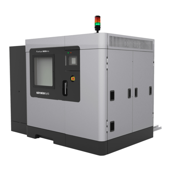
ABOUT THIS GUIDE This guide provides basic instructions for the Fortus 900mc. Instructions and specifications pertain to both the 900mc Gen 1 and Gen 2 models, unless otherwise stated. For additional information, contact your Stratasys representative. FORTUS 900MC PRINTER The Fortus 900mc™ 3D Production System incorporates the latest in innovative technologies that produce ®... -
Page 8: Front Of System
CANISTER BAY DOOR Allows access to the four canister bays, canister levers, and canister LEDs. FRONT OF SYSTEM The front of the system contains controls and status indicators for the Fortus 900mc printer. Signal Tower Power On Power Off... -
Page 9: Top Of System
EMERGENCY STOP Pressing the Emergency Stop button immediately removes power to the system. This button should be used only as an extreme measure to remove power to the system and should not be used or tested unnecessarily as the computer hard drive can be corrupted due to the hard shutdown. The system can be restarted by pulling the Emergency Stop button out to its original position and following the normal startup process. - Page 10 HEAD MAINTENANCE BRACKET The Head Maintenance Bracket is designed to hold the head assembly while performing maintenance on the head such as tip replacement. The red handle is designed so the top slide covers cannot be closed while the bracket is in place. Head Assembly Head Maintenance Bracket...
-
Page 11: Oven Components
OVEN COMPONENTS The oven is comprised of the oven door and everything that you see through the oven door window, including the platen and the tip wipe assembly. The oven is where parts are built. OVEN DOOR The oven door is locked by a solenoid during the building of a part. Pressing the Door button on the Operator Touchscreen will release the solenoid allowing you to open the door. - Page 12 OVEN LAMPS There are two LED oven lamps mounted in the two front upper corners of the oven. There is a lamp (light) switch on the touchscreen, which you can use to manually turn the light ON or OFF (Figure Warning: Oven lights are hot and are not a user replaceable item.
- Page 13 CAMERA A camera is housed within the front-left LED oven lamp mounted within the oven chamber. This camera is used to remotely monitor an active job build. TIP CLEANING ASSEMBLY The Tip Cleaning Assembly is located to the front, right side of the oven. The assembly consists of two flicker/ brush assemblies (1 for each tip) and a debris chute.
-
Page 14: Canister Bays
Bays (2X) The Fortus 900mc system has four operating material bays - 2 model and 2 support. The upper two bays hold model material; the bottom two bays hold support material. While building, two canisters will be active. An active canister has material filament loaded to the liquefiers (steady green LED). -
Page 15: Rear Of System
Onboard Computer ONBOARD COMPUTER The onboard computer is the central control unit for the Fortus 900mc. This computer also runs the touchscreen software that provides for the system's user interface. The UPS unit is a battery standby system that supplies power (AC voltage) to the computer, oven lights, and head cooling fan in the event of a loss of AC power. - Page 16 This system requires a high voltage connection, which is made at the top right-hand corner at the back of the system. High voltage is applied to the system using a Delta connection. The main breaker must be off until a Stratasys authorized Service Technician has verified the connection. This system is only provided with a Delta connection.
-
Page 17: Model Tag
MODEL TAG Use the following label to identify your system: • Serial Number - Refer to this number when requesting service. Model - The model number, the power requirements, and the company’s address and phone • number are given on the label. All patent numbers associated with the system are also listed on the label. -
Page 18: Available Materials
AVAILABLE MATERIALS The Fortus 900mc system can use a variety of material types: • ABSi model material used with SR-20 soluble support. ABS-M30 and ABS-M30i model materials used with SR-20, SR-30, or SR-35 soluble support. • SR-30 is ductile and dissolves up to three times faster than SR-20. -
Page 19: Ac Power Disconnection
AC POWER DISCONNECTION Any time service is being performed on the Fortus 900mc AC power must be removed to the system. Perform the system shutdown sequence on the system before removing power to the system. Make sure the main breakers at the facility site are in their OFF position before preceding to remove any electrical panels. - Page 20 Lockout Bar Flip the lockout bar to the locked position. Note that the circuit breakers cannot be returned to the ON position when the lockout bar is in the locked position. Secure the lockout bar with an external lock. The lockout bar will not stay in the locked position without an external lock.
-
Page 21: Operating Environment
10/100 Base T Ethernet • RJ45 connector Note: The Fortus 900mc will function in both DHCP or Static IP configurations. Use a standard Ethernet patch cable when connecting to a facility network (included in the • start-up installation kit). If connecting directly to a workstation an Ethernet cross over cable is... -
Page 22: Tools
TOOLS START-UP KIT CONTENTS The printer’s Start-Up Kit contains the Welcome Insert document, software CD, the common tools you will need to maintain the printer, and a variety of replacement parts. Use the following tables to identify the contents of the Start-Up Kit. -
Page 23: Safety Information
The following basic safety tips are given to ensure safe installation, operation, and maintenance of Stratasys equipment and are not to be considered as comprehensive on matters of safety. The Fortus 900mc printer is designed to be a safe and reliable rapid prototyping printer. Access to areas of the printer are potentially dangerous. - Page 24 Gloves: The gloves sign indicates that if you enter the area specified by the symbol you must wear safety gloves (provided in the Welcome Kit) which have been approved for high temperatures. Sharp Object: The sharp object sign indicates the presence of sharp objects. Do not touch sharp objects as they may cause a loss of body parts.
-
Page 25: Safety Precautions
SAFETY PRECAUTIONS The following components and areas of the printer are potential safety hazards. Take adequate precautions when using and maintaining the printer. OVEN Warning: Always wear safety gloves and long sleeves when working inside the oven. Components are hot. The oven temperature is extremely hot. -
Page 26: Stability Wedge Blocks
STABILITY WEDGE BLOCKS Back Wedge Block Placement Wedge Block (2X) Adjacent to the outside of the skid angle iron mount point Place the Wedge Blocks in position and then snug up the wedge to a gap of 0.25 inch (0.6 cm) between the system frame and the edge of the wedge. -
Page 27: General Safety Practices
Front Wedge Block Placement Only Wedge Block placed inside System Approximately 1.0 in. (2.5 cm) Note: Only the front left Wedge Block is placed on the inside of the system. This is done so the adjuster of the wedge block will not be visible after the front left kick panel is installed. -
Page 28: Basic User Operations
BASIC USER OPERATIONS The Operator Touchscreen is located on the front of the system. Icons are displayed on the screen that are universal and intuitive to use. Power On Button Power Off Button Operator Touchsceen The Operator Touchscreen allows you to: •... -
Page 29: Powering On The System
POWERING ON THE SYSTEM To turn the system ON: Press the flashing green button (Figure If there is a completed part in the system, remove the part from the system and install a new build sheet and close the door. Press the Materials/Tools icon from the touchscreen and then press the XYZ icon to auto home the platen. -
Page 30: User Interface
USER INTERFACE The following figure depicts the navigation buttons and status indicators of the Fortus 900mc touchscreen: Material Help Back Stop Light Door Login Build Pause Tools Previous Job Selected Job Next Job Queue Window System Log System State Health Monitor... -
Page 31: Queue Window
QUEUE WINDOW menu contains files downloaded from the Insight application on your PC workstation. Queue • Job Queue displays current jobs that are waiting in the queue. A list of stored sample jobs can be displayed by pressing the Sample Queue icon. •... -
Page 32: Tip Offset Menu
TIP OFFSET MENU This menu allows the user to adjust the XYZ calibration offsets. The thickness of the support material can also be adjusted. After adjustment, the user can press the Build Calibrations Box to verify the calibration. PART PLACEMENT MENU The Part Placement window allows the user to move the part manually to a position on the build sheet. -
Page 33: System Default Values
SYSTEM DEFAULT VALUES System defaults can be changed from the System Default menu. DISPLAY UNITS Select Display Units. • Inches or metric can be selected (factory setting is in English). USER PLACEMENT The part build location can be viewed or changed from the User Placement button. If User Placement is set to Off (default), the part will build in the center of the platen. -
Page 34: Building Screen
BUILDING SCREEN The Building Screen displays the progress of the part being built. Oven temperature is displayed as well as platen vacuum for large and small build sheets. The icon will turn green when vacuum is present. Pressing the Platen Vacuum button turns off the platen vacuum so a build sheet can be removed. When off, the button displays a Ø... -
Page 35: Loading/Unloading Material
LOADING/UNLOADING MATERIAL LOADING MATERIAL TO THE LIQUEFIER TIPS Note: Loading filament to the liquefiers is done in the Idle or Paused mode only, not while building. Caution: If the material type is changed, the tips must be changed. Perform the following steps to load material to the liquefier tips: Make sure the system is in the Pause or Idle mode. -
Page 36: Unloading Material From The Liquefier Tips
UNLOADING MATERIAL FROM THE LIQUEFIER TIPS Note: Unloading filament from the liquefiers is done in the Idle mode only, not while building or in a paused state. Perform the following steps to unload material from the liquefier tips: Make sure the system is in the Pause or Idle mode. From the Main Menu, select Operator Tools and the following screen will appear. -
Page 37: Changing Tips Or Material Type
CHANGING TIPS OR MATERIAL TYPE Note: If you are changing tips, or changing to a different material type, the user interface has a menu selection that guides you through the process. Caution: If the material type is changed, the tips must be changed. Perform the following steps to change tips an/or material type: Clean the oven and the tip wipe assembly. - Page 38 Place the head in the head maintenance bracket. Warning: Surfaces of the liquefier tips and heater block can be very hot. Loosen the two captive screws that clamp each liquefier tip in place. Remove the tips. Liquefier Clamp Screws Place the new liquefier tips in the head. Tighten the clamp screws. Note: Make sure the tips are fully inserted into heater block before tightening the clamp screws.
-
Page 39: Automatic Calibrations
AUTOMATIC CALIBRATIONS After tips are changed the user menu will prompt you to perform a series of automatic calibrations: Autocal Tips Calibration, Autohome XYZ, and Auto Z Calibration. Note: Perform an Autohome XYZ before initiating automatic calibration. Operator interaction is not required for Auto Z Stage Zero calibration. XY and Z Tip Offset requires that the operator analyze a calibration part and supply the system with correction values. -
Page 40: Adjust Xyz Calibration Offsets
ADJUST XYZ CALIBRATION OFFSETS Adjust XYZ Calibration registers the support tip relative to the model tip. The system automatically builds the calibration model when the Build Calibration Box button is pressed. Remove the build sheet from the platen and allow it to cool. Determine the XY Offset Adjustment. - Page 41 Tip Offset Adjustment Indicators Calibration Model X - Y Support Calibration English Units Toolpath X - Y Alignment Example: Best Indicators Centered Position Z Calibration Box This example requires an adjustment to Y of -.002 in. The X axis requires no adjustment. After the adjustments are made, a new calibration box can be run from this menu by pressing Build Calibration Box.
-
Page 42: Autohome Xyz
AUTOHOME XYZ When the AutoHome icon is pressed, the system will perform the following exercise with no operator interaction required: Note: AutoHome is used to move away from a limit switch. Finds the Z home limit switch. Finds the X home limit switch. Finds the Y home limit switch. -
Page 43: Basic Job Build Tasks
Nylon parts use a green tinted build sheet. Set the build sheet on the platen. • The Fortus 900mc can accommodate two sizes of build sheets. Make sure the build sheet that is used is centered on the platen. •... -
Page 44: Select A Job To Build
iii. Make sure the active model and support canister bays have filament loaded to the head (steady green LED). Make sure the loaded filament match the material requirements of the CMB file. Change material type if necessary. The touchscreen warns if there is a material mis-match. Make sure that the tip cleaning brush and tips are clean. -
Page 45: Build Job Warnings
Position Part Build Using the touchscreen, position the part on the displayed platen. Press the Build icon to initiate the building of the selected part. BUILD JOB WARNINGS If the system detects an issue that may affect a job build, the system displays one of the following warnings: Head has been changed. - Page 46 Need More Model (or Support) Material. • The total available material is less than the estimated amount for the part (CMB file). • If the system runs out of material before part completion, system will pause the build until material is added.
-
Page 47: Working With The Job Queues
WORKING WITH THE JOB QUEUES There are two queues available on the Fortus 900mc - the Job Queue and the Sample Job Queue. Use the Job Queue and Sample Queue buttons within the Operator Touchscreen to toggle between the two queues. - Page 48 - Unlock the oven door and top slide covers, clean tips, change materials Operator Control (including load/unload and canister removal/installation), move the head, or move the Z Stage. - Stops the current job. Stop Job...
-
Page 49: After A Job Build
AFTER A JOB BUILD Warning: Wear proper safety equipment when handling items inside the oven. Surfaces in the build chamber can be very hot. After a job build is complete, the system performs the following actions: The Z Stage is lowered and the head is parked. •... - Page 50 Carefully peel the part from the build sheet. • If the part does not peel easily, use the metal scraper included in your Startup Kit to carefully pry the part from the sheet. • The build sheet is intended for one-time use. Do not turn a build sheet over and place it on the platen.
-
Page 51: User Maintenance
Detailed instructions for each task make up the rest of this chapter. Please note that the testing of interlock/protective circuits is not applicable to the Fortus 900mc. Warning: always wear proper heat protective clothing when working inside the oven. -
Page 52: Daily Maintenance
DAILY MAINTENANCE CLEAN THE PLATEN The platen is the surface on which the build sheet is placed for modeling. If debris collects on the platen, it can adversely affect the vacuum which secures the build sheet to the platen. Remove the build sheet from the platen. Lift a corner of the build sheet to break the vacuum holding it to the platen or turn off vacuum •... -
Page 53: Empty The Purge Bucket
EMPTY THE PURGE BUCKET The purge bucket is located inside the oven. It catches the material that has been purged or wiped from the liquefiers and liquefier tips. The purge bucket should be emptied daily. Warning: Always wear safety gloves and long sleeves when working inside the oven. -
Page 54: Weekly Maintenance
WEEKLY MAINTENANCE VACUUM THE BUILD ENVELOPE Vacuum the build envelope to remove build material waste, debris, and dust. CLEAN/INSPECT TIP WIPE ASSEMBLY Inspect the Tip Wipe Assembly once a week. Replace parts as necessary when wear is detected. The brush and flicker are replaced as an assembly. - Page 55 For PPSF and ULTEM Material Only Standard Purge Ledge Inspect the flicker/brush assemblies. The top edge of the flicker should be straight. Replace the flicker if it is notched or bent - a small amount of wear is acceptable. The flicker can be replaced individually if the brush is acceptable for reuse.
-
Page 56: Quarterly Maintenance
QUARTERLY MAINTENANCE CLEAN THE TIP SENSOR PLUNGER Remove the plunger - gently pull up and out. Remove material residue on the top of the plunger with a razor blade. Replace the plunger in the sensor bracket making sure the flat surface is up. Tip Sensor Plunger Tip Sensor Bracket... -
Page 57: As Needed Maintenance
XYZ axis components. Please contact Stratasys Customer Support if you are interested in receiving a quote for these services or would like additional information. Failure to adhere to this schedule could lead to reduced life of XYZ components such as lead screws and bearings. -
Page 58: Supplemental Information
Virtually all system communication, interface and control takes place or originates from within electrical panel of the Fortus 900mc system. The electrical panel is not intended for customer/user access because potentially deadly electrical power sources are present. Safe electrical practices must be followed when performing service within this enclosure. - Page 59 Din Rail Detailed View (Gen II only, Serial Number > 1030) X MOTOR X MOTOR Y MOTOR Z MOTOR SAFETY RELAY SAFETY CONTACTOR SAFETY CONTACTOR MOTOR CONTROL OVEN BLOWER EX FAN FANS EB HEATER MAC MN MAIN MAC LINE OVEN LIGHTS...
-
Page 60: Auxiliary Panel (Gen 2 Only, Serial Number > 1030)
These functions are performed using an external compressed air source (non-lubricated) at 90-120 psi). Because of the large build area offered by the Fortus 900mc, two separate vacuum zones on the vacuum platen are provided. The zones are identified as the “inner” and “outer” and permit use of either large or small build sheets. -
Page 61: Connection To Electrical Supply
CONNECTION TO ELECTRICAL SUPPLY Caution: A licensed electrician must perform all wiring from service connection to the system - including all connectors, cables, and proper strain relief. Comply with all applicable local and national electric codes. Remove 10 screws that attach the Left Back Access Plate to the system, This provides access to the electrical junction box. - Page 62 Connect the system to the electrical service as follows: Warning: HIGH LEAKAGE CURRENT. Earth connection essential before connecting supply. • Line 1 connects to fuse block L1. • Line 2 connects to fuse block L2. • Line 3 connects to fuse block L3. •...
-
Page 69: Safety Interlock Summary (Gen 2 Only, Serial Number > 1030)
SAFETY INTERLOCK SUMMARY (GEN 2 ONLY, SERIAL NUMBER > 1030) • The one oven door and two top cover interlock sensor switches each utilize three contactor sets. One set is used to provide open/closed status to the system software. The other two sets of each sensor report status to the safety control relay. - Page 72 Customers, resellers, and Stratasys employees are encouraged to send comments about our documentation and training to c-support@stratasys.com. We greatly value your comments, review all of them, and use them to improve subsequent releases of the documentation. In your email message please include the document title, part number (located on the front cover), and page number.
Need help?
Do you have a question about the Fortus 900mc and is the answer not in the manual?
Questions and answers