Table of Contents
Advertisement
Quick Links
Advertisement
Table of Contents

Subscribe to Our Youtube Channel
Related Manuals for IS5 COMMUNICATIONS iES6 Series


Summary of Contents for IS5 COMMUNICATIONS iES6 Series
- Page 1 Intelligent 6 Port Managed Ethernet Switches iES6/iES6-S Series User’s Manual Version 1.12 2020 iS5 Communications Inc. 5895 Ambler Dr. Mississauga Ontario L4W 5B7 Tel: 1+ 905–670–0004 Fax: 1+ 289–401–5206 Website: www.iS5Com.com E-mail: support@iS5Com.com COPYRIGHT NOTICE...
- Page 2 Series User’s Manual Copyright © 2020 iS5 Communications Inc. All rights reserved. No part of this publication may be reproduced in any form without the prior written consent of iS5 Communications Inc. (iS5). TRADEMARKS iS5Com is a registered trademark of iS5. All other trademarks belong to their respective owners.
-
Page 3: Table Of Contents
CAUTION: SERVICE .................... 7 CAUTION: PHYSICAL ACCESS ................7 GETTING TO KNOW YOUR SWITCH ..............8 About the iES6 Series Intelligent Managed Switch ................ 8 Software Features ......................... 8 Hardware Features ........................8 HARDWARE OVERVIEW ..................9 Front Panel ........................... 9 Rear ............................ - Page 4 Series User’s Manual 5.1.3 Front Panel ..........................22 5.1.4 Basic setting ..........................23 5.1.4.1 Switch Setting......................23 5.1.4.2 Admin Password ....................... 23 5.1.4.3 IP Setting ........................24 5.1.4.4 SNTP (Time Setting) ....................25 5.1.4.5 LLDP ........................27 5.1.4.6 Backup & Restore ..................... 27 5.1.4.7...
- Page 5 Series User’s Manual Commands Set List — System Commands Set ................51 Commands Set List — Port Commands Set ................... 52 Commands Set List — RSTP command set ................... 53 Commands Set List — SNMP command set .................. 55 Commands Set List —...
-
Page 6: Caution: Laser
This product contains no user-serviceable parts. Attempted service by unauthorized personnel shall render all warranties null and void. Changes or modifications not expressly approved by iS5 Communications Inc. could invalidate specifications, test results, and agency approvals, and void the user's authority to operate the equipment. -
Page 7: Getting To Know Your Switch
Getting to Know Your Switch About the iES6 Series Intelligent Managed Switch The iES6 series switches are powerful, managed industrial grade switches with numerous features. These switches can operate under a wide temperature range, dusty environments, and in humid conditions. The switches can be managed either by using the WEB, TELNET, directly using the Console port on the switch, or any third-party SNMP software. -
Page 8: Hardware Overview
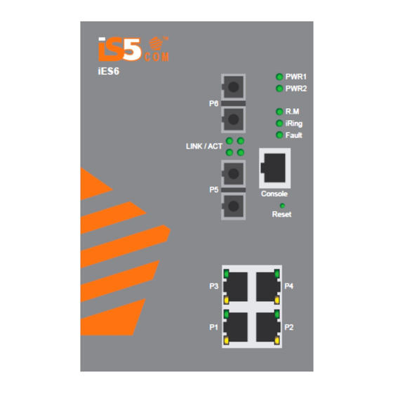
Series User’s Manual Hardware Overview Front Panel The product description is as shown below. Port Description Ports 1-4 10/100 RJ45 fast 6 x 10/100Base-T(X) RJ45 fast Ethernet ports support auto-negotiation. Default Setting : Ethernet ports (8) Speed: auto Duplex: auto... -
Page 9: Rear
Series User’s Manual Front Panel LED’s are shown in the table below. Item Description Color Status Function PWR1 Green Power supply 1 operational. PWR2 Green Power Supply 2 operational. Green Switch operating as iRing Master. iRing enabled. iRing Green Slowly blinking iRing topology broken. -
Page 10: Bottom
Series User’s Manual Bottom The image below shows the 10 position terminal block and ground lug of the iES6 and iES6-S switch. Figure 3 - 10 Position Terminal Block and Ground Lug Side On the full DIN version, the holes circled in red are the side mounting holes for the Panel bracket mounting option. -
Page 11: Hardware Installation
Series User’s Manual Hardware Installation DIN Rail Mounting Each switch has a DIN-Rail bracket on the rear panel that allows the switch to be mounted on a DIN Rail. To mount the switch on a DIN Rail follow the steps below. -
Page 12: Panel Mounting Option
Series User’s Manual Panel Mounting Option The switch can also has an option to be panel or wall mounted. The following steps show how to mount the switch on a panel or wall. 1. Install the Panel mounting hardware onto the switch. The user can choose rear mounting or side mounting. -
Page 13: Power Connections
Series User’s Manual Power Connections The iES6 and iES6-S Series Ethernet switch supports 3 different dual redundant power supplies (PWR1 and PWR2): 1. LV: Dual Input 10-48VDC 2. MV: Dual Input 36-75VDC 3. HV: Single Input 85-264VAC or 88-370VDC with a Single 10-48VDC Backup. - Page 14 Series User’s Manual Terminal Description Connection Number PWR2 (-) : Negative Connected to the negative terminal of the 2 10-48VDC power source. RLY NO Failsafe relay, normally open contact. RLY CM Failsafe relay, common contact. No connection 2. MV: Dual Input 36-75VDC...
-
Page 15: Console Connection
Series User’s Manual Terminal Description Connection Number PWR1 (-/N) – Neutral or Connected to the neutral terminal of the 85-264VAC Negative power source or the negative terminal of the 88-370VDC power source. Connected to the safety ground terminal for AC units or –... -
Page 16: Cables
Ethernet Cables The iES6 series switches have standard Ethernet ports. According to the link type, the switches use either CAT 3, 4, 5, 5e UTP cables to connect to any other network device (PCs, servers, switches, routers, or hubs). See below for cable specifications. -
Page 17: Fiber Optics
Not used Fiber Optics The iES6 Series are available with optional fiber ports. The fiber optical ports are available in either Multimode or Singlemode, and with either SC or ST type connectors. The transceivers are also available for longer distances as required. -
Page 18: Console Cable
Series User’s Manual Console Cable The iES6 Series switches can be managed via the console port on the front face using the RS-232 cable provided, and a local PC. The console cable pin assignment is as shown below. PC pin out (male) assignment... -
Page 19: Web Management
Series User’s Manual WEB Management Configuration by Web Browser This section introduces the configuration by Web browser. 5.1.1 About Web-based Management An embedded HTML web site resides in the flash memory of the CPU board. It contains advanced management features which allow you to manage the switch from anywhere on the network via a standard web browser such as Microsoft Internet Explorer. - Page 20 Series User’s Manual Figure 12 - Login Screen The login screen appears. Key in the username and password. The default username and password are “admin”. Click Enter or click OK.. The change default password screen of the Web UI appears.
-
Page 21: System Information
Series User’s Manual 5.1.2 System Information Figure 14 - System Information Interface System Information The system information will display the configuration of Basic Setting / Switch Setting page. Enable Location Alert Click PWR1 and PWR2 LED’s of the switch will start to flash. -
Page 22: Basic Setting
Series User’s Manual 5.1.4 Basic setting Switch Setting 5.1.4.1 Figure 15 - Switch setting interface The following table describes the labels for the Switch Setting screen. Label Description System Name Assign the name of switch. The maximum length is 64 bytes. -
Page 23: Ip Setting
Series User’s Manual IP Setting 5.1.4.3 The IP Settings and DHCP client function can be configured through IP configuration. Figure 17 - IP Configuration Interface The following table describes the labels for the IP Configuration Interface screen. Label Description Enables or disables the DHCP client function. -
Page 24: Sntp (Time Setting)
Series User’s Manual SNTP (Time Setting) 5.1.4.4 SNTP The SNTP (Simple Network Time Protocol) settings allow you to synchronize switch clocks over the Internet. Figure 18 - SNTP Configuration Interface The following table describes the labels for the SNTP screen. - Page 25 Series User’s Manual Local Time Zone Conversion from UTC Time at 12:00 UTC AST - Atlantic Standard -4 hours 8 am EDT - Eastern Daylight EST - Eastern Standard -5 hours 7 am CDT - Central Daylight CST - Central Standard...
-
Page 26: Lldp
Series User’s Manual LLDP 5.1.4.5 The LLDP (Link Layer Discovery Protocol) function allows the switch to advertise its information to other nodes on the network and store the information it discovers. Figure 19 - LLDP Configuration Interface The following table describes the labels for the LLDP screen. -
Page 27: Upgrade Firmware
Series User’s Manual The following table describes the labels for the Backup & Restore screen. Label Description TFTP Server IP Address Enter in the TFTP server IP. Restore File Name Enter the file name. Restore Click Restore to restore the configurations. -
Page 28: Port Status
Series User’s Manual The following table describes the labels for the Port Control screen. Label Description Port No. Port number for setting. State Enables/Disables Port Control. Speed/Duplex Set Auto-negotiation, 100 full, 100 half, 10 full or 10 half. Flow Control Supports symmetrical and asymmetrical mode to avoid packet loss when congestion occurs. -
Page 29: Redundancy
Series User’s Manual 5.1.7 Redundancy 5.1.7.1 Fast Recovery Mode The Fast Recovery Mode can be set to connect multiple ports to one or more switches. The IES6 S with its fast recovery mode will provide redundant links. Fast Recovery mode supports 4 priorities, only the first priority will be the act port, the other ports configured with other priority will be the backup ports. -
Page 30: Ichain
Series User’s Manual The following table describes the labels for the iRing screen. Label Description iRing Enables iRing. Ring Master There should be only one Ring Master in a ring. However, if two or more switches have Ring Master enabled, the switch with the lowest MAC address will become the Ring Master and the others will become the Backup Masters. -
Page 31: Ibridge
Series User’s Manual The following table describes the labels for the iChain screen. Label Description Enable Enables the iChain function. Uplink Port Select the port (1 - 8) to be the Uplink Port. Edge Port Defines the port as an Edge Port. Only one Edge Port of the Edge Switch needs to be defined. -
Page 32: Rstp
Series User’s Manual The following table describes the labels for the iBridge screen. Label Description Enable Enables the iBridge function Vendor Choose the vendors that you want to interoperate with. Ring Port Choose the port that will connect to the ring. -
Page 33: Rstp Setting
Series User’s Manual RSTP Setting The RSTP function can be enabled or disabled and parameters set for each port via the RSTP Setting interface. Figure 31 - RSTP Setting interface The following table describes the labels for the RSTP Setting screen. -
Page 34: Rstp Information
Series User’s Manual Label Description port. Enter a number 1 to 200000000. Priority (0-240) Enter which port should be blocked by setting the priority on the LAN. Enter a number between 0 and 240. The value of priority must be a multiple of 16. - Page 35 Series User’s Manual The following table describes the labels for the RSTP Information screen. Label Description Root Priority A value used to identify the root bridge. The bridge with the lowest value and with the highest priority is selected as the root.
-
Page 36: Vlan
Series User’s Manual 5.1.8 VLAN A Virtual LAN (VLAN) is a logical network grouping that limits the broadcast domain, which allows isolation of network traffic. Only the members of the VLAN will receive traffic from the same members of VLAN. Basically, creating a VLAN from a switch is logically equivalent of reconnecting a group of network devices to another Layer 2 switch. -
Page 37: Snmp - Trap Setting
Series User’s Manual Figure 34 - SNMP Agent Setting Interface The following table describes the labels for the SNMP Agent Settings screen. Label Description SNMP agent Version Three SNMP versions are supported: SNMP V1/SNMP V2c, and SNMP V3. The SNMP V1/SNMP V2c agent uses a community string match for authentication, which means SNMP servers access objects with read-only or read/write permissions. - Page 38 Series User’s Manual Figure 35 - SNMP Trap Setting Interface The following table describes the labels for SNMP Trap Setting. Label Description Server IP The server IP address to receive Trap. Community Community for authentication. Trap Version Trap Version supports V1 and V2c.
-
Page 39: Snmp - Snmp-V3 Setting
Series User’s Manual 5.1.9.3 SNMP – SNMP-V3 Setting Figure 36 - SNMP Setting Figure 37 -Access Table iS5 Communications Inc. -
Page 40: System Warning
Series User’s Manual Label Description Context Table Configure SNMP v3 context table. Assign the context name of context table. Click "Apply" to change context name User Table 1. Configure SNMP v3 user table. 2. User ID: set up the user name. -
Page 41: System Warning - Syslog Setting
Series User’s Manual 5.1.10.1 System Warning - SYSLOG Setting The SYSLOG is a protocol to transmit event notification messages across networks. Please refer to RFC 3164 - The BSD SYSLOG Protocol. Figure 38 - System Warning – SYSLOG Setting Interface The following table describes the labels for the SYSLOG Setting screen. -
Page 42: System Warning - Smtp Setting
Series User’s Manual Label Description Page Select LOG page. Reload To get the newest event logs and refresh this page. Clear Clear log. 5.1.10.3 System Warning - SMTP Setting SMTP is Short for Simple Mail Transfer Protocol. It is a protocol for e-mail transmissions across the Internet. -
Page 43: System Warning - Event Selection
Series User’s Manual 5.1.10.4 System Warning – Event Selection SYSLOG and SMTP are the two warning methods supported by the system. Check the corresponding box to enable the system event warning method required. Please note that the check box cannot be checked while SYSLOG or SMTP is disabled. -
Page 44: System Warning - Fault Relay Alarm
Series User’s Manual 5.1.10.5 System Warning – Fault Relay Alarm When any selected fault event is happened, the Fault LED in switch panel will light up and the electric relay will signal at the same time. Figure 42 - Fault Alarm Interface 5.1.11 Save Configuration... -
Page 45: Factory Default
Series User’s Manual 5.1.12 Factory Default Figure 44 - Factory Default Interface To reset switch to the factory default configuration, click Reset . The default configuration will be applied after the next restart of the switch. The following table describes the labels for the Factory Default screen. -
Page 46: Command Line Interface Management
Series User’s Manual Command Line Interface Management About CLI Management Besides WEB-based management, iES6/iES6-S Series also supports CLI management. The switch console port or Telnet can be used to configure the switch via the CLI. CLI Management by RS-232 Serial Console (9600, 8, none, 1, none) Use an RJ45 to DB9-F cable to connect to the switch’s console and to a local PC’s COM port. - Page 47 Series User’s Manual Figure 48 - Serial Port Setup (4) Press Enter on the keyboard for the Console login screen to appear. Use the keyboard to enter the Console Username and Password which is same as the Web Browser password, then press Enter.
- Page 48 Series User’s Manual CLI Management by Telnet Users can use “TELNET” to configure the switches. The default value is as below: IP Address: 192.168.10.1 Subnet Mask: 255.255.255.0 Default Gateway: 192.168.10.254 User Name: admin Password: same as the Web Browser password Note: First login into device requires changes of the default password.
- Page 49 Series User’s Manual CLI Command Modes (Levels) Modes Access Method Prompt Exit Method About This Model User EXEC Begin a session with switch> Enter logout or The user command your switch. quit. available at the level of user is the subset of those available at the privileged level.
-
Page 50: Commands Set List - System Commands Set
Series User’s Manual Symbol of Command Levels Mode Symbol of Command Level User EXEC Privileged EXEC Global configuration VLAN database Interface configuration Commands Set List — System Commands Set iES6 Series Commands Level Description Example show config Show switch switch>show config... -
Page 51: Commands Set List - Port Commands Set
Series User’s Manual iES6 Series Commands Level Description Example restart default Restore to default Switch(config)#default admin username Changes a login switch(config)#admin username xxxxxx [Username] username. (maximum 10 words) admin password Specifies a password switch(config)#admin password xxxxxx [Password] (maximum 10 words) -
Page 52: Commands Set List - Rstp Command Set
Series User’s Manual iES6 Series Commands Level Description Example no security Disable security of switch(config)#interface fastEthernet 2 interface switch(config-if)#no security state Use the state interface switch(config)#interface fastEthernet 2 [Enable | Disable] configuration command switch(config-if)#state Disable to specify the state mode of operation for Ethernet ports. - Page 53 Series User’s Manual iES6 series Commands Level Description Example switch within this interval, the RSTP topology is recomputed. RSTP hello-time [seconds] G Use the RSTP hello-time switch(config)# RSTP hello-time 3 global configuration command to specify the interval (1-10) between hello bridge protocol data units (BPDUs).
-
Page 54: Commands Set List - Snmp Command Set
Series User’s Manual iES6 series Commands Level Description Example RSTP admin-p2p Admin P2P of STP priority switch(config)#interface fastEthernet 2 [Auto|True|False] on this interface. switch(config-if)# rstp admin-p2p Auto RSTP admin-edge Admin Edge of RSTP switch(config)#interface fastEthernet 2 [True|False] priority on this interface. -
Page 55: Commands Set List - Tftp Command Set
Series User’s Manual iES6 Series Commands Level Description Example no snmp snmpv3-user G Remove specified user of switch(config)# no snmp snmpv3-user [User Name] SNMPv3 agent. Privacy test01 password AuthPW PrivPW password password could be empty. [Authentication Password] [Privacy Password]... - Page 56 Series User’s Manual iES6 Series Commands Level Description Example [IP address] smtp authentication Enable SMTP auth. switch(config)#smtp authentication smtp account Configure authentication switch(config)#smtp account User [account] account smtp password Configure authentication switch(config)#smtp password [password] password smtp rcptemail Configure Rcpt e-mail...
-
Page 57: Commands Set List - Sntp Command Set
Series User’s Manual Commands Set List — SNTP command set iES6 Series Commands Level Description Example sntp enable Enable SNTP function switch(config)#sntp enable sntp daylight Enable daylight saving switch(config)#sntp daylight time, if SNTP function is inactive, this command can’t be applied. -
Page 58: Commands Set List - Iring Command Set
Series User’s Manual Commands Set List — iRing command set iES6 Series Commands Level Description Example iRing enable G Enable iRing switch(config)# iring enable iRing master G Enable iRing master switch(config)# iring master iRing ring-linking G Enable iRing linking... -
Page 59: Technical Specifications - Update Base On Latest Datasheet
Series User’s Manual Technical Specifications 1024 MAC addresses Technology Store-and-Forward MAC Table Switching latency: 7 μs Processing Switching bandwidth: 1.2 Gbps Switch Properties RSTP (IEEE 802.1 D-2004) Enable / disable ports Port-based VLAN SNMPv3 authentication and privacy encryption Security Features...
Need help?
Do you have a question about the iES6 Series and is the answer not in the manual?
Questions and answers