
Related Manuals for IS5 COMMUNICATIONS iES26GF


Summary of Contents for IS5 COMMUNICATIONS iES26GF
- Page 1 User’s Manual iES26GF Intelligent 26 Port Managed Gigabit Ethernet Switch IEC61850-3 and IEEE1613 Compliant Version 1.2.3, Feb 2018 © 2018 iS5 Communications Inc. All rights reserved. UM-iES26GF-1.2.3-EN.docx...
-
Page 2: Copyright Notice
User’s Manual COPYRIGHT NOTICE © 2018 iS5 Communications Inc. All rights reserved. No part of this publication may be reproduced in any form without the prior written consent of iS5 Communications Inc. (iS5). TRADEMARKS iS5Com is a registered trademark of iS5. All other trademarks belong to their respective owners. -
Page 3: Table Of Contents
Federal Communications Commission Radio Frequency Interference Statement ...... 1 Caution: LASER ............................ 1 Caution: Service ..........................1 Caution: Physical Access ........................1 Getting Started .................. 2 About iES26GF .......................... 2 Software Features........................2 Hardware Features........................2 Hardware Overview ................3 Front Panel ..........................3 Rear Panel View ........................ - Page 4 User’s Manual IP Setting ..........................24 IPv6 Configuration ........................24 SNTP ............................25 Daylight Saving Time ......................26 Switch Time ..........................29 HTTPS Configuration ....................... 29 SSH ............................30 Telnet ............................30 LLDP ............................31 MODBUS TCP .......................... 34 Backup &...
- Page 5 Command Line Interface Management ................. 145 CLI Management by RS-232 Serial Console (115200, 8, none, 1, none) ........ 145 CLI Management by Telnet ....................147 Technical Specification ................ 166 Appendix A: iES26GF Modbus Information ..........169 UM-iES26GF-1.2.3-EN.docx Pages 4 of 4...
-
Page 6: Fcc Statement And Cautions
This product contains no user-serviceable parts. Attempted service by unauthorized personnel shall render all warranties null and void. Changes or modifications not expressly approved by iS5 Communications Inc. could invalidate specifications, test results, and agency approvals, and void the user's authority to operate the equipment. -
Page 7: Getting Started
The iES26GF is a powerful managed industrial switch for power station applications with many features. The iES26GF is an IEC 61850-3 and IEEE 1613 compliant switch which can operate under a wide temperature range, in dusty environments, and humid conditions. -
Page 8: Hardware Overview
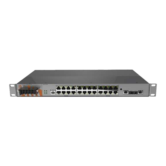
User’s Manual HARDWARE OVERVIEW 2.1 Front Panel Product description Port Description 10/100 RJ-45 Up to 24 x 10/100Base-T(X) RJ-45 fast Ethernet ports supporting auto-negotiation. fast Ethernet Default Setting: ports Speed: auto Duplex: auto Flow control: disable Gigabit ports 2 X 10/100/1000Base-T(X) RJ45 or 2 X 1000Base-X SFP or Combo 2 X... -
Page 9: Rear Panel View
10. LED for ports 25 and 26 Link / ACT status 11. LED for Combo Copper Ports Link/ACT status 2.3 Power Panel The iES26GF’s power connections are as follows: Figure 3 - Power Panel View Note: RLY COM– Relay Com RLY NO –... - Page 10 User’s Manual Chassis Connections Terminal No Description Connection PWR1 (L)–Live Connected to the (Live) terminal of an AC power source PWR1 (G)–Ground Power supply 1 round connection. PWR1 (N)–Neutral Connected to the (Neutral) terminal of an AC power source.
-
Page 11: Hardware Installation
User’s Manual Hardware Installation 3.1 Rack Mount Assembly The iES26GF comes with a kit for rack mount assembly. Figure 4- iES26GF Dimensions UM-iES26GF-1.2.3-EN.docx Pages 6 of 169... -
Page 12: Wiring
User’s Manual 3.2 Wiring WARNING Do not disconnect modules or wires unless power has been turned off or the area is known to be non-hazardous. Ensure that the proper supply voltage is supplied as indicated on the power supply label. -
Page 13: Power Inputs
User’s Manual Power Inputs The iES26GF supports dual redundant, hot swappable power supplies, Power Supply 1 (PWR1) and Power Supply 2 (PWR2). The connections for PWR1 and PWR2 are located on the terminal block. To connect power, follow the steps below: 1) Remove the cover designed for protection from the terminal block. -
Page 14: Fault Relay
User’s Manual Fault Relay The relay contact of the terminal block connector is used to detect user-configured events. The switch provides fail open and fail close options to form relay circuits based on requirements. The contacts are energized upon power-up of the unit and remain energized unless a critical error occurs. -
Page 15: Connection
3.3 Connection Ethernet Cables The iES26GF switch has standard Ethernet ports. According to the link type, these switches use CAT 3, 4, 5, or 5e UTP cables to connect to other network devices i.e. PCs, servers, switches, routers, or hubs. Refer to the following table for cable specifications. - Page 16 User’s Manual The iES26GF switch supports auto MDI/MDI-X operation; a straight-through cable can be used to connect a PC to the switch. The table below shows the 10Base-T/100Base-T(X), MDI and MDI-X port pin outs. 10/100 Base-T MDI/MDI-X pin Assignments...
-
Page 17: Console Cable
User’s Manual Console Cable The iES26GF switch can be managed via the console port. Using the supplied standard DB-9 to RJ45 cable, you can connect to a local PC. Console Cable pin Assignments PC pin out (male) assignment DB9 to RJ 45... -
Page 18: Sfp
User’s Manual For ports 25 and 26, the iES26GF has fiber optical ports with options for SFP, SC, and ST connectors. The fiber optical ports are in Multimode (0 to 550M, 850 nm with 50/125 µm, 62.5/125 µm fiber) and Singlemode with LC connector. -
Page 19: Iring/Ichain
User’s Manual iRing/iChain iRing Three or more switches can be connected to form a ring topology with network redundancy capabilities by following the steps below. 1. Connect each switch to form a daisy chain using an Ethernet or fiber optic cable. -
Page 20: Dual Homing
User’s Manual Dual Homing Dual Homing is used to connect a ring topology to a RSTP network environment. Choose the two switches (Switch A & B) from the ring to connect the switches in the RSTP network (backbone switches). -
Page 21: Redundancy
User’s Manual Redundancy Use of redundancy for minimizing system downtime is one of the most important concerns for industrial networking devices. iRing and iBridge, two iS5Co ’s proprietary redundant ring technologies, feature faster recovery times compared to the existing redundancy technologies widely used in commercial applications, such as STP, RSTP, and MSTP. -
Page 22: Ichain Introduction
User’s Manual 4.2 iChain Introduction iChain is a revolutionary network redundancy technology which enhances network redundancy for any backbone network, providing ease-of-use and maximum fault-recovery times, flexibility, compatibility, and cost-effectiveness. The self-healing Ethernet technology designed for distributed and complex industrial networks enables the network to recover in less than 30 milliseconds (in full- duplex Gigabit operation) or 10 milliseconds (in full-duplex Fast Ethernet operation) for up to 250 switches if at any time a segment of the chain fails. -
Page 23: Stp/Rstp/Mstp
User’s Manual 4.3 STP/RSTP/MSTP STP/RSTP Introduction STP (Spanning T r e e Protocol), its advan ced ve r s i o n s RSTP (Rapid Spanning Tree Protocol) and MSTP (Multiple Spanning Tree Protocol), are designed to prevent network loops and provide network redundancy. -
Page 24: Management
An embedded HTML web site resides in the flash memory of the CPU board. It contains advanced management features that allow the user to manage the iES26GF switch from anywhere on the network via a standard web browser such as Microsoft Internet Explorer. -
Page 25: Basic Settings
User’s Manual Figure 17 – Main Interface 5.1 Basic Settings System Information Configuration Figure 18 – System Information Configuration interface The system information will display the configuration of Basic/Switch Setting page. UM-iES26GF-1.2.3-EN.docx Pages 20 of 169... -
Page 26: Banner
User’s Manual The following table describes the labels for the System Information Configuration screen. Label Description An administratively assigned name for the managed node. By convention, this is the node's fully-qualified domain name. A domain name is a text string consisting of alphabets (A-Z, a-z), digits (0-9), and System Name minus sign (-). -
Page 27: Admin Password
User’s Manual Admin Password Admin Password allows the username and password for the Web Management login to be changed. Figure 20 - System Password interface The following table describes the labels for the System Password screen. Label Description User Name... -
Page 28: Authentication Method
User’s Manual Authentication Method Configure how a user is authenticated when he/she logs into the switch via one of the management interfaces. Figure 22 - Authentication Method Configuration interface The following table describes the labels for the Authentication Method Configuration screen. -
Page 29: Ip Setting
User’s Manual IP Setting You can configure the IP Settings and DHCP client function through IP Configuration screen. Figure 24 - IP Configuration interface The following table describes the labels for the IP Configuration screen. Label Description Enables or disables DHCP Client function. When the DHCP Client function... -
Page 30: Sntp
User’s Manual The following table describes the labels for the IPv6 Configuration screen. Label Description Auto Add a checkmark in Configured to enable Auto Configuration. Configuration Address Enter a IPv6 Address. The default is 192.0.2.1 Prefix Enter Prefix. Router Enter Router. -
Page 31: Daylight Saving Time
User’s Manual Daylight Saving Time This page allows you to configure the Time Zone. Figure 27 - Time Zone Configuration interface The following table describes the labels for the Time Zone Configuration screen. Label Description Lists various time zones worldwide. Select appropriate Time Zone from the drop-down list and click Save to set it up. - Page 32 User’s Manual The user can set the Acronym of the time zone. This is a User Acronym configurable acronym to identify the time zone. (Range: Up to 16 characters) This is used to set the clock forward or backward according to the configurations set below for a defined Daylight Saving Time duration.
- Page 33 User’s Manual Local Time Zone Conversion from UTC Time at 12:00 UTC November Time Zone - 1 hour 11 am Oscar Time Zone -2 hours 10 am ADT - Atlantic Daylight -3 hours 9 am AST - Atlantic Standard...
-
Page 34: Switch Time
User’s Manual Switch Time Configure date and time on this page. Figure 28 - Switch Time Configuration interface The following table describes the labels for the Switch Time Configuration screen. Mode Description Modify Current Date in the following order according to your Current Date preference: Year –... -
Page 35: Ssh
User’s Manual Secure Shell (SSH) is a cryptographic network protocol for operating network services securely over an unsecured network. Select SSH Configuration Mode on this page. Figure 30 - SSH Configuration interface The following table describes the labels for the SSH Configuration screen. -
Page 36: Lldp
User’s Manual LLDP LLDP (Link Layer Discovery Protocol) function allows the switch to advertise its identity, abilities, and neighbours to other nodes on the network and store the discovered information. Select LLDP Configuration, LLDP Neighbour Information, and Port Statistics on the following pages. - Page 37 User’s Manual Neighbours This page provides a status overview for all LLDP neighbors. The following table contains information for each port on which an LLDP neighbor is detected. Figure 33 - LLDP Neighbour Information The following table describes the columns for the LLDP Neighbour screen.
- Page 38 User’s Manual LLDP Global Counters This page provides an overview of all LLDP traffic. Two types of counters are shown. Global counters will apply settings to the whole switch stack, while local counters will apply settings to specified switches.
-
Page 39: Modbus Tcp
User’s Manual The following table describes the columns for the LLDP Statistics Local Counters screen. Label Description Local Port The port that receives or transmits LLDP frames Tx Frames The number of LLDP frames transmitted on the Local Port... -
Page 40: Backup & Restore Configuration
User’s Manual Backup & Restore Configuration The user can save current EEPROM values for the switch to the TFTP server or restore them from the TFTP configuration page. A local PC can be used instead of a TFTP server. -
Page 41: Dhcp Server/Relay
User’s Manual 5.2 DHCP Server/Relay The switch provides Dynamic Host Configuration Protocol (DHCP) server functions. By enabling DHCP, the switch will become a DHCP server and will assign dynamically IP addresses and related configuration information such as subnet mask and default gateway to network clients. -
Page 42: Dhcp Dynamic Client List
User’s Manual DHCP Dynamic Client List When DHCP server functions are activated in the DHCP Server Configuration dialog box, the switch will collect DHCP client information and display it in the following table. Figure 40 - DHCP Dynamic Client List interface The following table describes the columns and labels for the DHCP Dynamic Client List screen. -
Page 43: Dhcp Relay Agent
User’s Manual The following table describes the columns and labels for the DHCP Client List screen. Label Description MAC Address Enter the MAC address to be added to the Static Client List. IP Address Enter the MAC address to be added to the Static Client List. - Page 44 User’s Manual The following table describes the columns and labels for the DHCP Relay Configuration screen. Label Description Indicates the existing DHCP Relay Agent Mode. The modes include: • Relay Mode Enabled: activates DHCP relay. • Disabled: disables DHCP relay Indicates the DHCP Relay Server IP address.
- Page 45 User’s Manual The following table describes the columns and labels for the DHCP Relay Statistics screen. Label Description Transmit to Server The number of packets relayed from the client to the server Transmit Error The number of packets with errors when being sent to clients...
-
Page 46: Port Setting
User’s Manual 5.3 Port Setting Port Control By this function, you can set the state, negotiation, speed/duplex, flow control, and security for the port. Port Setting allows you to manage individual ports of the switch, including traffic, power, and trunks. -
Page 47: Port Trunk
User’s Manual Port Trunk Configuration This page allows you to configure the Aggregation Hash Mode and the aggregation group. Figure 46 - Aggregation Mode Configuration interface (Hash Code Contributors) The following table describes the columns and labels for the Hash Code Contributors screen. -
Page 48: Lacp Port
User’s Manual The following table describes the columns and labels for the Aggregation Group Configuration screen. Label Description Indicates the ID of each aggregation group. Normal means no Group ID aggregation. Only one group ID is valid per port. -
Page 49: System Status
User’s Manual The following table describes the columns and labels for the LACP Port Configuration screen. Label Description Port The switch port number. Controls whether LACP is enabled on this switch port. LACP will form LACP Enabled an aggregation when 2 or more ports are connected to the same partner. - Page 50 User’s Manual Port Status This page provides an overview of the LACP status for all ports. Figure 50 - LACP Status interface The following table describes the columns and labels for the LACP Status screen. Label Description Port Switch port number.
- Page 51 User’s Manual Port Statistics This page provides an overview of the LACP statistics for all ports. Figure 51 - LACP Statistics interface The following table describes the columns and labels for the LACP Statistics screen. Label Description Port Switch port number.
-
Page 52: Loop Protection
User’s Manual Loop Protection This feature is used to prevent a loop attack. When receiving loop packets, the port will be disabled automatically, preventing the loop attack from affecting other network devices. Configuration Figure 52 - Global Settings interface (Global Configuration) The following table describes the columns and labels for the Global Settings screen. - Page 53 User’s Manual Status The Loop Protection Status is shown on the following page. Figure 54 - Loop Protection Status interface The following table describes the columns and labels for the Loop Protection Status screen. Label Description Port The switch port number of the logical port.
-
Page 54: Redundancy
User’s Manual 5.4 Redundancy iRing Configuration iS5 supports three ring topologies: Ring M aster, Coupling Ring, and Dual Homing. You can configure the settings in the interface below. Figure 55- iRing Configuration interface The following table describes the columns and labels for the iRing Configuration screen. -
Page 55: Ibridge
User’s Manual Figure 56 - iChain Configuration interface The following table describes the columns and labels for the iChain Configuration screen. Label Description Enable Check to enable iChain function Uplink Port; 1st Ring Port From the drop-down list, choose the first port connecting to the ring. -
Page 56: Rstp
User’s Manual RSTP The Rapid Spanning Tree Protocol (RSTP) is an evolution of the Spanning Tree Protocol (STP). It provides faster convergence of spanning tree after a topology change. The system also supports STP and will detect a connected device that is running STP or RSTP protocol automatically. - Page 57 User’s Manual Port Setting This page allows the user to configure the current RSTP port configurations, and change them as well. Figure 59 - RSTP Port Setting interface UM-iES26GF-1.2.3-EN.docx Pages 52 of 169...
- Page 58 User’s Manual The following table describes the labels for the RSTP Port Setting screen. Label Description Port The switch port number of the logical RSTP port Enabled Controls whether RSTP is enabled on this switch port. The Auto setting will set the path cost as appropriate by the physical link speed, using the 802.1D 2004 recommended values.
- Page 59 User’s Manual Port Status This page displays the RSTP port status for physical ports of the switch. Figure 61 - RSTP Port Status interface The following table describes the labels for the RSTP Port Status screen. Label Description Check this box to enable an automatic refresh of the page at regular Auto-refresh intervals.
-
Page 60: Mstp
User’s Manual MSTP Bridge Settings This page allows you to configure STP system settings. The settings are used by all STP Bridge instances in the switch . Figure 62 - STP Bridge Configuration interface UM-iES26GF-1.2.3-EN.docx Pages 55 of 169... - Page 61 User’s Manual The following table describes the labels for the RSTP Port Status screen. Label Description The version of the STP protocol. Valid values include STP, RSTP and Protocol Version MSTP. Controls the bridge priority. Lower numeric values have better priority.
-
Page 62: Msti Mapping
User’s Manual MSTI Mapping This page allows you to examine and change the configurations of current STP MSTI bridge instances. Figure 63 - MSTI Configuration interface The following table describes the labels for the MSTI Configuration screen. Label Description The name which identifies the VLAN to MSTI mapping. -
Page 63: Cist Ports
User’s Manual The following table describes the labels for the MSTI Configuration screen. Label Description MSTI This is the bridge instance. CIST is the default instance, which is always active. Indicates bridge priority. The lower the value, the higher the priority. The... -
Page 64: Msti Ports
User’s Manual The following table describes the labels for the CIST Aggregated Port Configuration screen. Label Description Port The switch port number to which the following settings will be applied. STP Enabled Check to enable STP for the port Configures the path cost incurred by the port. - Page 65 User’s Manual Figure 66 – MST1 MSTI Port Configuration interface The following table describes the labels for the MST1 MSTI Port Configuration screen. Label Description The switch port number of the corresponding STP CIST (and MSTI) Port port Configures the path cost incurred by the port. Auto will set the path cost according to the physical link speed by using the 802.1D-...
- Page 66 User’s Manual The following table describes the labels for the STP Bridges screen. Label Description This is the bridge instance. It can also be linked to the STP detailed bridge MSTI status. Bridge ID The bridge ID of this bridge instance.
- Page 67 User’s Manual Port Statistics This page displays the STP port statistics for the currently selected switch. Figure 69 - STP Statistics interface The following table describes the labels for the STP Statistics screen. Label Description Port The switch port number to which the following settings will be applied.
-
Page 68: Fast Recovery
User’s Manual Fast Recovery Figure 70 - Fast Recovery interface The following table describes the labels for the Fast Recovery screen. Label Description Enable Enable Fast Recovery function Ports can be set to 26 priorities. Only the port with the highest priority will be the active port. -
Page 69: Dual Port Recovery
User’s Manual Dual Port Recovery Dual Port Recovery mode is defined to work with unmanaged devices/switches or ring of switches. This feature can be set to on single port of switches on both sides of unmanaged ring. The iES22GF with Dual Port Recovery mode will provide redundant links. - Page 70 User’s Manual When link of port 1 on switch 2 returns to be linked up, the switch 1 port 1 is in “Forwarding” state and in this case the “No Link” port is changing its status to be “Blocking” port.
-
Page 71: Vlan
User’s Manual 5.5 VLAN VLAN Membership You can view and change VLAN membership configurations for a selected switch stack in this page. Up to 64 VLAN’s are supported. This page allows for adding and deleting VLAN’s as well as adding and deleting port members of each VLAN. -
Page 72: Port Configurations
User’s Manual Port Configurations This page allows you to set up VLAN ports individually. Figure 73 - VLAN Port Configuration interface The following table describes the labels for the VLAN Port Configuration screen. Label Description Ethertype for This field specifies the Ether type used for custom S-ports. This is a global setting custom S- for all custom S-ports. - Page 73 User’s Manual More Details on Port Types Below is a detailed description of every port type, including Unaware, C-port, S-port, and S- custom-port. TPID stands for the modified tag protocol identifier (TPID) value of VLAN Tags. Description Ingress action...
- Page 74 User’s Manual Figure 74 - Unaware and C-port Port Types UM-iES26GF-1.2.3-EN.docx Pages 69 of 169...
- Page 75 User’s Manual Figure 75 - S-port and S-custom Port Types UM-iES26GF-1.2.3-EN.docx Pages 70 of 169...
- Page 76 User’s Manual Examples of VLAN Settings 1) VLAN Access Mode Figure 76 - VLAN Access Mode topology For Switch A: Port 7 is VLAN Access mode = Untagged 20 Port 8 is VLAN Access mode = Untagged 10 Below are the switch’s settings.
- Page 77 User’s Manual 2) VLAN 1Q Trunk Mode Figure 77 - VLAN 1Qtrunk Mode topology For Switch B: Port 1 = VLAN 1Qtrunk mode = tagged 10, 20 Port 2 = VLAN 1Qtrunk mode = tagged 10, 20 Below are the switch settings.
- Page 78 User’s Manual 3) VLAN Hybrid Mode For VLAN Hybrid Mode: Port 1 VLAN Hybrid mode = untagged 10 Tagged 10, 20 Below are the switch settings. UM-iES26GF-1.2.3-EN.docx Pages 73 of 169...
- Page 79 VLAN QinQ mode is usually adopted when there are unknown VLANs, as shown in the figure below. VLAN “X” = Unknown VLAN Figure 78 - VLAN QinQ Mode topology 5) iES26GF Port 1 VLAN Settings UM-iES26GF-1.2.3-EN.docx Pages 74 of 169...
-
Page 80: Private Vlan
User’s Manual VLAN ID Settings When setting the management VLAN, only the same VLAN ID port can be used to control the switch. iES26GF VLAN Settings: Private VLAN Private VLAN Membership Configuration The private VLAN membership configuration for the switch can be monitored and modified here. -
Page 81: Port Isolation Configuration
User’s Manual The following table describes the labels for the Private VLAN Membership Configuration screen. Description Label Delete Check to delete the entry. It will be deleted during the next save. Private VLAN ID Indicates the ID of this private VLAN. -
Page 82: Snmp
User’s Manual 5.6 SNMP SNMP System Configuration Configure the Simple Network Management Protocol (SNMP) on this page. Figure 81 - SNMP System Configuration interface The following table describes the labels for the SNMP System Configuration screen. Label Description Indicates existing SNMP mode. Possible modes include:... -
Page 83: Snmpv3 Communities Configuration
User’s Manual The following table describes the labels for the SNMP Trap Configuration screen. Label Description Indicates the trap destination mode operation. Possible modes are: Trap Mode Enabled: Enable SNMP trap mode operation. Disabled: Disable SNMP trap mode operation. -
Page 84: Snmp Users Configuration
User’s Manual The following table describes the labels for the SNMPv3 Community Configuration screen. Label Description Delete Check to delete the entry. It will be deleted during the next save. Community Indicates the community access string to permit access to SNMPv3 agent. - Page 85 User’s Manual The following table describes the labels for the SNMPv3 User Configuration screen. Label Description Delete Check to delete the entry. It will be deleted during the next save. An octet string identifying the engine ID that this entry should belong to. The string must contain an even number between 10 and 64 hexadecimal digits, but all-zeros and all-'F's are not allowed.
-
Page 86: Snmp Group Configuration
User’s Manual SNMP Group Configuration This page allows you to configure SNMPv3 group table. Figure 85 - SNMPv3 Group Configuration interface The following table describes the labels for the SNMPv3 Group Configuration screen. Label Description Delete Check to delete the entry. It will be deleted during the next save. - Page 87 User’s Manual The following table describes the labels for the SNMPv3 View Configuration screen. Label Description Delete Check to delete the entry. It will be deleted during the next save. A string identifying the view name that this entry should belong to. The...
-
Page 88: Snmp Access Configuration
User’s Manual SNMP Access Configuration This page allows you to configure SNMPv3 access table. The entry index keys are Group Name, Security Model, and Security Level. Figure 87 - SNMPv3 Access Configuration interface The following table describes the labels for the SNMPv3 Community Configuration screen. -
Page 89: Traffic Prioritization
User’s Manual 5.7 Traffic Prioritization Storm Control This page allows you to configure the storm control settings for all switch ports. There is a storm rate control for unicast, multicast (unknown), and broadcast ingress traffic. Figure 88 - Storm Control Configuration interface The following table describes the labels for the Storm Control Configuration screen. - Page 90 User’s Manual The following table describes the labels for the QoS Ingress Port Classification screen. Label Description Port The port number for which the configuration below applies It controls the default QoS class All frames are classified to a QoS class. There is a one to one mapping between QoS class, queue, and priority.
-
Page 91: Port Tag Remarking
User’s Manual Port Tag Remarking This page provides an overview of QoS Egress Port Tag Remarking for all switch ports. Figure 90 - QoS Egress Port Tag Remarking interface The following table describes the labels for the QoS Egress Port Tag Remarking screen. -
Page 92: Port Dscp
User’s Manual Port DSCP This page allows you to configure basic QoS Port DSCP Configuration settings for all switch ports. Figure 91 - QoS Port DSCP Configuration interface The following table describes the labels for the QoS Port DSCP Configuration screen. -
Page 93: Port Policing
User’s Manual Port Policing This page allows you to configure Policers settings for all switch ports. Figure 92 - QoS Ingress Port Policers interface The following table describes the labels for the QoS Ingress Port Policers screen Label Description Port The port number for which the configuration below applies. -
Page 94: Port Scheduler
User’s Manual The following table describes the labels for the QoS Ingress Queue Policers screen. Label Description Port The port number for which the configuration below applies. Enable(E) Check to enable queue policer for individual switch ports Save Click Save to save changes. - Page 95 User’s Manual QoS Egress Port Scheduler and Shapers This page allows you to configure Scheduler and Shapers for a specific port. This is accessed by selecting specific port on the Port Scheduler or Port Shaping screens. 1) Strict Priority Figure 95 - QoS Egress Port Scheduler and Shapers Port 1 This table describes the labels for the QoS Egress Port Scheduler and Shapers Policers screen.
- Page 96 User’s Manual 2) Weighted Figure 96 - QoS Egress Port Scheduler and Shapers Port 1 This table describes the labels for the QoS Egress Port Scheduler and Shapers Port 1 screen. Label Description Controls whether the scheduler mode is Strict Priority or Scheduler Mode Weighted on this switch port.
-
Page 97: Port Shaping
User’s Manual Configures the rate of each port shaper. The default value is 500. Port Shaper Rate This value is restricted to 100 to 1000000 when the Unit is kbps, and it is restricted to 1 to 3300 when the Unit is Mbps. -
Page 98: Dscp Based Qos
User’s Manual DSCP Based QoS This page allows you to configure basic QoS DSCP-based QoS Ingress Classification settings for all switches. Figure 98 - DSCP-Based QoS Ingress Classification interface The following table describes the labels for the DSCP-Based QoS Ingress Classification screen. -
Page 99: Dscp Translation
User’s Manual DSCP Translation This page allows you to configure basic QoS DSCP translation settings for all switches. DSCP translation can be done in Ingress or Egress. Figure 99 - DSCP Translation interface The following table describes the labels for the DSCP Translation screen. -
Page 100: Dscp Classification
User’s Manual DSCP Classification This page allows you to configure the mapping of QoS class to DSCP value. Figure 100 - DSCP Classification interface The following table describes the labels for the DSCP Classification screen. Label Description QoS Class Actual QoS class Drop Precedence Level. - Page 101 User’s Manual Figure 102 - QCE Configuration interface UM-iES26GF-1.2.3-EN.docx Pages 96 of 169...
- Page 102 User’s Manual The following table describes the labels for the QCE Configuration screen. Label Description Port Members Check to include the port in the QCL entry. By default, all ports are included. Key configurations include: Tag: value of tag; it can be Any, Untag, or Tag.
-
Page 103: Qos Statistics
User’s Manual QoS Statistics This page provides the statistics of individual queues for all switch ports. Figure 103 - Queuing Counters The following table describes the labels for the Queuing Counters screen. Label Description The logical port number for the statistics displayed. Click on the port Port number to see Detailed Port Statistics. -
Page 104: Qcl Status
User’s Manual QCL Status This page shows the QCL status for different QCL users. Each row describes the QCE that is defined. It is a conflict if a specific QCE is not applied to the hardware due to hardware limitations. The maximum number of QCEs is 256 on each switch. -
Page 105: Multicast
User’s Manual 5.8 Multicast The Internet Group Management Protocol (IGMP) is used by IP hosts to register their dynamic multicast group membership. IGMP has 3 versions: IGMP v1, v2 and v3. For details, refer to RFC 1112, 2236 and 3376. IGMP Snooping improves the performance of networks that carry multicast traffic. -
Page 106: Igmp Snooping Vlan Configuration
User’s Manual IGMP Snooping VLAN Configuration Each page shows up to 99 entries from the VLAN table, with a default value of 20, selected by the Entries Per Page input field. When first visited, the web page will show the first 20 entries from the beginning of the VLAN Table. -
Page 107: Igmp Snooping Status
User’s Manual IGMP Snooping Status This page provides IGMP snooping status. Figure 107 - IGMP Snooping Status The following table describes the labels for the IGMP Snooping Status screen. Label Description VLAN ID The VLAN ID of the entry... -
Page 108: Igmp Snooping Group Information
User’s Manual IGMP Snooping Group Information Entries in the IGMP Group Table are shown on this page. The IGMP Group Table is sorted first by VLAN ID, and then by group. Each page shows up to 99 entries from the IGMP Group table, by default being 20, selected through the entries per page input field. -
Page 109: Security
User’s Manual 5.9 Security Remote Control Security Configurations Remote Control Security allows you to limit remote access to the management interface. When enabled, client requests which are not allowed will be rejected. Figure 109 - Remote Control Security Configuration interface... - Page 110 User’s Manual The following table describes the labels for the Device Binding screen. Label Description Indicates the device binding operation for each port. Possible modes are: ---: disable Mode Scan: scans IP/MAC automatically, but no binding function Binding: enables binding. Under this mode, any IP/MAC that does not match the entry will not be allowed to access the network.
- Page 111 User’s Manual The following table describes the labels for the Alias IP Address screen. Label Description Specifies alias IP address. Keep 0.0.0.0 if the device does not have an alias Alias IP Address IP address. Save Click Save to save all changes.
- Page 112 User’s Manual Figure 113 - DDOS Prevention interface The following table describes the labels for the DDOS Prevention screen. Label Description Mode Enables or disables DDOS prevention of the port Indicates the level of DDOS detection. Possible levels are:...
-
Page 113: Device Description
User’s Manual Device Description This page allows you to configure device description settings. Figure 114 - Device Description interface The following table describes the labels for the Device Description screen. Label Description Indicates device types. Possible types are: --- (no specification), IP Camera,... - Page 114 User’s Manual Stream Check This page allows you to configure stream check settings. Figure 115 - Steam Check interface The following table describes the labels for the Steam Check screen. Label Description Mode Enables or disables Stream Monitoring of the port Indicates the action to take when the stream gets low.
-
Page 115: Acl
User’s Manual ACL Ports Configuration This page allows you to configure the Access Control List (ACL) parameters or access control entries (ACE) of each switch port. These parameters will affect the frames received on a port unless the frame matches a specific ACE. -
Page 116: Acl Rate Limiter Configuration
User’s Manual ACL Rate Limiter Configuration This page allows you to configure the rate limiter for the ACL of the switch. Figure 117 - ACL Rate Limiter Configuration The following table describes the labels for the ACL Rate Limiter Configuration screen. -
Page 117: Access Control List
User’s Manual Access Control List This page shows the Access Control List (ACL), which is made up of the ACEs defined on this switch. Each row describes an ACE that is defined. The maximum number of ACEs is 512 on each switch. -
Page 118: Acl Status
User’s Manual The following table describes the labels for the ACE Configuration screen. Label Description Indicates the ingress port of the ACE. Possible values are: Ingress Port All: The ACE will match all ingress port. Port: The ACE will match a specific ingress port. - Page 119 User’s Manual Figure 120 - ACL Status interface The following table describes the labels for the ACL Status screen. Label Description User Indicates the ACL user. Indicates the ingress port to which the ACE will apply. Ingress All: the ACE will match all ports.
-
Page 120: Aaa
User’s Manual AAA – Authentication Server Configuration Authentication, Authorization and Accounting (AAA)—this page allows you to configure the AAA server. Figure 121 - Authentication Server Configuration interface The following table describes the labels for the Authentication Server Configuration screen. -
Page 121: Radius Overview
User’s Manual The Secret—up to 29 characters long—shared between the RADIUS Authentication Secret Server and the switch. Radius Accounting Server Configuration The RADIUS Accounting Server number for which the configuration below applies. Enabled Enable the RADIUS Accounting Server by checking this box. -
Page 122: Radius Details
User’s Manual The following table describes the labels for the Radius Authentication Server Status Overview. Label Description The RADIUS server number. Click to navigate to detailed statistics of the server. The IP address and UDP port number (in <IP Address>: <UDP Port> notation) IP Address of the server. - Page 123 User’s Manual Label Description Use the server’s drop-down box to determine which server’s information Server #n ↓ will be shown by selecting server #n. ‘n’ is from 1 to 5. Check this box to refresh the page automatically. Automatic refresh occurs Auto-refresh every 3 seconds.
- Page 124 User’s Manual The number of authentication timeouts to the server. After a timeout, the client may retry to the same server, send to a different radiusAuthClientE Timeouts server, or give up. A retry to the same xtTimeouts server is counted as a retransmit as well as a timeout.
-
Page 125: Nas (802.1X)
User’s Manual NAS (802.1x) Overview This page allows you to configure the IEEE 802.1X and MAC-based authentication system and port settings. The IEEE 802.1X standard defines a port-based access control procedure that prevents unauthorized access to a network by requiring users to first submit credentials for authentication. One or more central servers (the backend servers) determine whether the user is allowed access to the network. - Page 126 User’s Manual Since the server has not failed (because the X seconds have not expired), the same server will be contacted when the next back-end authentication server requests from the switch. This scenario will loop forever. Therefore, the server timeout should be smaller than the supplicant's EAPOL Start frame retransmission rate.
- Page 127 User’s Manual Configuration 1) Network Access Server (NAS) Configuration Figure 124 - Network Access Server Configuration interface The following table describes the labels for the Network Access Server Configuration screen. Label Description Indicates if 802.1X and MAC-based authentication is globally enabled or Mode disabled on the switch.
- Page 128 User’s Manual This setting applies to the following modes, i.e. modes using the Port Security functionality to secure MAC addresses: M AC-Based Auth.: When the NAS module uses the Port Security module to secure MAC addresses, the Port Security module needs to check for activity on the MAC address in...
- Page 129 User’s Manual encapsulates the EAP part of the frame into the relevant type (EAPOL or RADIUS) and forwards it. When authentication is complete, the RADIUS server sends a special packet containing a success or failure indication. Besides forwarding the result to the supplicant, the switch uses it to open up or block traffic on the switch port connected to the supplicant.
- Page 130 User’s Manual Unlike port-based 802.1X, MAC-based authentication is not a standard, but merely a best-practices method adopted by the industry. In MAC-based authentication, users are called clients, and the switch acts as the supplicant on behalf of clients. The initial frame (any kind of frame) sent by a client is snooped by the switch, which in turn uses the client's MAC address as both username and password in the subsequent EAP exchange with the RADIUS server.
- Page 131 User’s Manual NAS Switch This page provides an overview of the current NAS port states. Figure 125 - Network Access Server Switch Status interface The following table describes the labels for the Network Access Server Switch Status screen. Label Description The switch port number.
- Page 132 User’s Manual NAS Port This page provides detailed IEEE 802.1X statistics for a specific switch port using port-based authentication. For MAC-based ports, only selected backend server (RADIUS Authentication Server) statistics are shown. Use the Port’s drop-down list to select details about which Port to be displayed.
- Page 133 User’s Manual 1) EAPOL Counters These supplicant frame counters are available for the following administrative states: • Force Authorized • Force Unauthorized • 802.1X The following table describes the seven receive and three transmit EAPOL counters. Rx/Tx Name IEEE Name...
- Page 134 User’s Manual 2) Backend Server Counters These backend (RADIUS) frame counters are available for the following administrative states: • 802.1X • MAC-based Auth. The following table describes the four receive and one transmit Backend Server counters. Name IEEE Name...
- Page 135 User’s Manual 3) Last Supplicant/ Client Info Information about the last supplicant/client that attempted to authenticate. This information is available for the following administrative states: • 802.1X • MAC-based Auth. Name IEEE Name Description dot1xAuthLast The MAC address of the last supplicant/client.
-
Page 136: Warning
User’s Manual 5.10 Warning The Warning function is very important for managing the switch. The switch can be managed using SYSLOG, E-MAIL, and Fault Relay. The function helps the user to monitor the switch’s status at a remote site. When events occur, a warning message will be sent to the appointed server, E-MAIL, or relay fault on the switch panel. -
Page 137: System Warning
User’s Manual System Warning SYSLOG Setting The SYSLOG is a protocol that transmits event notifications across networks. For more details, please refer to RFC 3164 - The BSD SYSLOG Protocol. Figure 128 - System Log Configuration interface The following table describes the labels for the System Log Configuration screen. -
Page 138: Event Selection
User’s Manual The following table describes the labels for the SMTP Setting screen. Label Description E-mail Alert Enables or disables transmission of system warnings by e-mail. The SMTP server IP address (or domain name address). The default SMTP Server Address is 0.0.0.0... - Page 139 User’s Manual Select the SYSLOG event for a specific port number. Possible selections are: • Disable SYSLOG • Link Up • Link Down • Link Up and Link Down Select a SMTP option for a specific port number. Possible selections are: •...
-
Page 140: Monitoring And Diagnostic
User’s Manual 5.11 Monitoring and Diagnostic MAC Table MAC Address Table Configuration The MAC address table can be configured on this page. Set timeouts for entries in the dynamic MAC table and configure the static MAC table here. Figure 131 - MAC Address Table Configuration 1) Aging Configuration By default, dynamic entries are removed from the MAC after 300 seconds (as shown above). -
Page 141: Mac Address Table
User’s Manual 3) Static MAC Table Configurations The static entries in the MAC table are shown in this table. The static MAC table can contain up to 64 entries. The entries are for the whole stack, not for individual switches. The MAC table is so rted first by VLAN ID and then by MAC address. -
Page 142: Port Statistics
User’s Manual The following table describes the labels for the MAC Address Table screen. Label Description Type Indicates whether the entry is a static or dynamic entry. M AC address The MAC address of the entry. VLAN The VLAN ID of the entry. - Page 143 User’s Manual Figure 134 - Detailed Port Statistics Port 1 The following table describes the labels for the Detailed Ports Statistics Port 1 screen. Label Description Rx and Tx Packets The number of received and transmitted (good and bad) packets.
-
Page 144: Port Monitoring
User’s Manual Port Monitoring To solve network problems, selected traffic can be copied or mirrored to a mirror port where a frame analyzer can be attached to analyze the frame flow. The traffic to be copied to the mirror port is selected as follows: •... -
Page 145: Sfp Monitor
User’s Manual The following table describes the labels for the System Log Information screen. Label Description The ID (>= 1) of the system log entry The level of the system log entry. The following level types are supported: Info: provides general information... -
Page 146: Ping
User’s Manual The following table describes the labels for the SFP Monitor screen. Label Description Port no Port Number. Temperature (°C) Temperature of the SFP Vcc (V) Transceiver supply voltage TX Bias (mA) Transmitted laser bias current TX Power (µW) Transmit power of the SFP RX Power (µW) -
Page 147: Ping6
User’s Manual 64 bytes from ::10.10.132.20: icmp_seq=2, time=0ms 64 bytes from ::10.10.132.20: icmp_seq=3, time=0ms 64 bytes from ::10.10.132.20: icmp_seq=4, time=0ms Sent 5 packets, received 5 OK, 0 bad You can configure the following properties of the issued ICMP packets: The following table describes the labels for the ICMP Ping screen. - Page 148 User’s Manual The following table describes the labels for the ICMPv6 Ping screen. Label Description IP Address The destination IP Address The payload size of the ICMP packet. Values range from 2 bytes to 1452 Ping Length bytes. Ping Count The count of the ICMP packet.
-
Page 149: Factory Defaults
User’s Manual 5.12 Factory Defaults You can reset the configuration of the stack switch on this page. The IP configuration and/or User/Password are retained only if the respective boxes are checked when the switch is restored to factory defaults. -
Page 150: Command Line Interface Management
User’s Manual 5.14 Command Line Interface Management Besides Web-based management, the iES6GF also supports Command Line Interface (CLI) management. Use either the Console port or Telnet to manage the switch via the CLI. Details are shown below. CLI Management by RS-232 Serial Console (115200, 8, none, 1,... - Page 151 User’s Manual Figure 143 - Tera Term: Serial port setup interface 4) Press Enter for the Console login screen to appear. Use the keyboard to enter the Console Username and Password which is same as the Web Browser password (admin for both), then press Enter.
-
Page 152: Cli Management By Telnet
User’s Manual CLI Management by Telnet You can use Telnet to configure the switch. The default values are: IP Address: 192.168.10.1 Subnet Mask: 255.255.255.0 Default Gateway: 192.168.10.254 User Name: admin Password: admin Follow the steps below to access the console via Telnet. - Page 153 User’s Manual 1) Command Groups Welcome to iES26GF Command Line Interface. UM-iES26GF-1.2.3-EN.docx Pages 148 of 169...
- Page 154 User’s Manual 2) System Configuration [all] [<port_list>] Name [<name>] Description [<description>] Contact [<contact>] Location [<location>] Version Log Configuration Log Level [info|warning|error] Log Server Mode [enable|disable] Log Server Address [<ip_addr_string>] Log Lookup [<log_id>] [all|info|warnup Log Lookup [<log_id>] [all|info|warning|error] System> lingerer]...
- Page 155 User’s Manual Neighbour List Ping <ip_target> [(Length <ping_length>)] [(Count <ping_count>)] [(Interval <ping_interval>)] Route Add <ip_net> <ip_gateway> Route Delete <ip_net> <ip_gateway> Route List SNTP Configuration SNTP Mode [enable|disable] SNTP Server Add <ip_addr_string> SNTP Server Delete 4) Port Configuration [<port_list>] [up|do wn] Mode [<port_list>]...
- Page 156 User’s Manual 6) VLAN Configuration [<port_list>] PVID [<port_list>] [<vid>|none] FrameType [<port_list>] [all|tagged|untagged] IngressFilter [<port_list>] [enable|disable] tx_tag [<port_list>] [untag_pvid|untag_all|tag_all] PortType [<port_list>] [unaware|c-port|s-port|s-custom-port] EtypeCustomSport [<etype>] Add <vid>|<name> [<ports_list>] Forbidden Add <vid>|<name> [<port_list>] VLAN> Delete <vid>|<name> Forbidden Delete <vid>|<name> Forbidden Lookup [<vid>] [(name <name>)] Lookup [<vid>] [(name <name>)] [combined|static|nas|all]...
- Page 157 User’s Manual 9) Security Switch Password <password> Auth Authentication Secure Shell Security/switch> Hypertext Transfer Protocol over HTTPS Secure Socket Layer RMON Remote Network Monitoring Security Switch Authentication Configuration Console [no|local|radius] [local|radius] Security/switch/a Telnet [no|local|radius] [local|radius] uth> SSH [no|local|radius] [local|radius]...
- Page 158 User’s Manual Security Network Psec Port Security Status Security/Network Network Access Server (IEEE 802.1X) > Access Control List Security Network Psec Switch [<port_list>] Security/Network / Psec> Port [<port_list>] Security Network NAS Configuration [<port_list>] Mode [enable|disable] State [<port_list>] [auto|authorized|unauthorized|macbased] Reauthentication [enable|disable] Security/Network ReauthPeriod [<reauth_period>]...
- Page 159 User’s Manual Security Network ACL Configuration [<port_list>] Action [<port_list>] [permit|deny] [<rate_limiter>][<port_redirect>] [<mirror>] [<logging>] [<shutdown>] Policy [<port_list>] [<policy>] Rate [<rate_limiter_list>] [<rate_unit>] [<rate>]up Add [<ace_id>] [<ace_id_next>] [(port <port_list>)] [(policy <policy> <policy_bitmask>)][<tagged>] [<vid>] [<tag_prio>] [<dmac_type>][(etype [<etype>] [<smac>] [<dmac>]) | (arp [<sip>] [<dip>] [<smac>] [<arp_opcode>] [<arp_flags>]) | [<sip>] [<dip>] [<protocol>] [<ip_flags>]) | (icmp [<sip>]...
- Page 160 User’s Manual Security Network DHCP Configuration Mode [enable|disable] Server [<ip_addr>] Security/Network /DHCP> Information Mode [enable|disable] Information Policy [replace|keep|drop] Statistics [clear] Security AAA Configuration Radius-server timeout [<timeout>] Radius-server retransmit [<retransmit>] Radius-server deadtime [<deadtime>] radius-server key [<key>] radius-server nas-ip-address [<ipv4_addr>|disable] Security/AAA>...
- Page 161 User’s Manual Configuration Version [<stp_version>] Txhold [<holdcount>] MaxHops [<maxhops>] MaxAge [<max_age>] FwdDelay [<delay>] bpduFilter [enable|disable] bpduGuard [enable|disable] recovery [<timeout>] CName [<config-name>] [<integer>] Status [<msti>] [<port_list>] Msti Priority [<msti>] [<priority>] Msti Map [<msti>] [clear] Msti Add <msti> <vid> Port Configuration [<stp_port_list>] Port Mode [<stp_port_list>] [enable|disable]...
- Page 162 User’s Manual LACP Configuration [<port_list>] Mode [<port_list>] [enable|disable] Key [<port_list>] [<key>] Prio [<port_list>] [<prio>] LACP> System Prio [<sysprio>] Role [<port_list>] [active|passive] Status [<port_list>] Statistics [<port_list>] [clear] Timeout [<port_list>] [fast|slow] LLDP Configuration [<port_list>] Mode [<port_list>] [enable|disable] Optional_TLV [<port_list>] [port_descr|sys_name|sys_descr|sys_capa|mgmt_addr] [enable|disable] Interval [<interval>]...
- Page 163 User’s Manual Port QueuePolicer Mode [<port_list>] [<queue_list>] [enable|disable] Port QueuePolicer Rate [<port_list>] [<queue_list>] [<bit_rate>] Port Scheduler Mode [<port_list>] [strict|weighted] Port Scheduler Weight [<port_list>] [<queue_list>] [<weight>] Port Shaper Mode [<port_list>] [enable|disable] Port Shaper Rate [<port_list>] [<bit_rate>] Port QueueShaper Mode [<port_list>] [<queue_list>]...
- Page 164 User’s Manual [<dport>]) | (ipv6 [<protocol>] [<sip_v6>] [<dscp>] [<sport>] [<dport>])] [<class>] [<dp>] [<classified_dscp>] QCL Delete <qce_id> QCL Lookup [<qce_id>] QCL Status [combined|static|conflicts] QCL Refresh Mirror Configuration [<port_list>] Mirror> Port [<port>|disable] Mode [<port_list>] [enable|disable|rx|tx] Config Save <ip_server> <file_name> Config> Load <ip_server> <file_name> [check]...
- Page 165 User’s Manual User Lookup [<index>] Group Add <security_model> <security_name> <group_name> Group Delete <index> Group Lookup [<index>] View Add <view_name> [included|excluded] <oid_subtree> View Delete <index> View Lookup [<index>] Access Add <group_name> <security_model> <security_level> [<read_view_name>] [<write_view_name>] Access Delete <index> Access Lookup [<index>] Trap Mode [enable|disable] Trap Lookup [<conf_name>]...
- Page 166 User’s Manual Firmware Load <ip_addr_string> <file_name> NetLoad <url> Firmware> Information Swap Configuration [<clockinst>] PortState <clockinst> [<port_list>] [enable|disable|internal] ClockCreate <clockinst> [<devtype>] [<twostep>] [<protocol>] [<oneway>] [<clockid>] [<tag_enable>] [<vid>] [<prio>] ClockDelete <clockinst> [<devtype>] DefaultDS <clockinst> [<priority1>] [<priority2>] [<domain>] CurrentDS <clockinst> ParentDS <clockinst>...
- Page 167 User’s Manual Wireless mode <clockinst> [<port_list>] [enable|disable] Wireless pre notification <clockinst> <port_list> Wireless delay <clockinst> [<port_list>] [<base_delay>] [<incr_delay>] SlaveDS <clockinst> Loop Protect Configuration Mode [enable|disable] Transmit [<transmit-time>] Shutdown [<shutdown-time>] Loop Protect> Configuration [<port_list>] Port Port Mode [<port_list>] [enable|disable] Port Action [<port_list>] [shutdown|shut_log|log] Port Transmit [<port_list>] [enable|disable]...
- Page 168 User’s Manual Event Configuration Syslog SystemStart [enable|disable] Syslog PowerStatus [enable|disable] Event> Syslog SnmpAuthenticationFailure [enable|disable] Syslog RingTopologyChange [enable|disable] Syslog Port [<port_list>] [disable|linkup|linkdo wn|both] DHCPServer Mode [enable|disable] Setup [<ip_start>] [<ip_end>] [<ip_mask>] [<ip_router>] DHCPServer> [<ip_dns>] [<ip_tftp>] [<lease>] [<bootfile>] Configuration RIP> Mode [enable|disable]...
- Page 169 User’s Manual Mode [enable|disable] Add [<ip_addr>] [<port_list>] [web_on|web_off] [telnet_on|telnet_off] [snmp_on|snmp_off] RCS> Del <index> Configuration FastRecovery Mode [enable|disable] FastRecovery> Port [<port_list>] [<fr_priority>] DualPort Configuration Mode [enable|disable] Interval <integer> DualPort> Retry <integer> TimeoutDelay <integer> DebugMessage [enable|disable] O-Ring Configuration [enable|disable] Port <port>...
- Page 170 User’s Manual Device Binding Mode [enable|disable] Port Mode [<port_list>] [disable|scan|binding|shutdown] Port DDOS Mode [<port_list>] [enable|disable] Port DDOS Sensibility [<port_list>] [low|normal|medium|high] Port DDOS Packet [<port_list>] [rx_total|rx_unicast|rx_multicast|rx_broadcast|tcp|udp] Port DDOS Low [<port_list>] [<socket_number>] Port DDOS High [<port_list>] [<socket_number>] Port DDOS Filter [<port_list>] [source|destination] Port DDOS Action [<port_list>]...
-
Page 171: Technical Specification
User’s Manual TECHNICAL SPECIFICATION Table 1. Technical Specification Description Specification 10/100Base-T(X) RJ45 10/100/1000Base-T(X) RJ45, or 1000Base-X SFP, or 1000SX MM ST/SC, or 1000LX SM ST/SC RS-232 Serial Console Port RS-232 in RJ-45 connector with console cable. 115200 bps, 8, N, 1... - Page 172 User’s Manual Description Specification unregistered IPMCv4 Flooding • Warnings (Syslog and SMTP) and Fault Alarm (power failure) • Monitoring and Diagnostics—MAC Table and Port Statistics (ports monitoring including for SFP ports, system information, issuing ICMP PING packets troubleshooting connectivity issues) •...
- Page 173 User’s Manual Table 3. Standards and Management Description Specification IEEE 802.3 for 10Base-T IEEE 802.3u for 100Base-TX and 100Base-FX IEEE 802.3ab for 1000Base-T IEEE 802.z for 1000Base-X IEEE 802.3x for Flow control IEEE IEEE 802.3ad for LACP (Link Aggregation Control Protocol) Standards IEEE 802.1D Spanning Tree Protocol (STP)
-
Page 174: Appendix A: Ies26Gf Modbus Information
User’s Manual APPENDIX A: IES26GF MODBUS INFORMATION *Device ID/PLC is 1 *04 Read Input Register (3x) should be used. *The returned values are in hex format Address Description VendorName ProductName Version MacAddress SysName SysDescription SysLocation 1024 SysContact PortStatus: 4096...
Need help?
Do you have a question about the iES26GF and is the answer not in the manual?
Questions and answers