
Related Manuals for IS5 COMMUNICATIONS IES12G


Summary of Contents for IS5 COMMUNICATIONS IES12G
- Page 1 User’s Manual IES12G Intelligent 12 Port Managed Gigabit Ethernet Switch IES12G https://is5com.com/products/ Version 1.72.2, May 20, 2020 © 2020 iS5 Communications Inc. All rights reserved.
- Page 2 User’s Manual COPYRIGHT NOTICE © 2020 iS5 Communications Inc. All rights reserved. No part of this publication may be reproduced in any form without the prior written consent of iS5 Communications Inc. (iS5). TRADEMARKS iS5Com is a registered trademark of iS5. All other trademarks belong to their respective owners.
-
Page 3: Table Of Contents
Hardware Installation ................ 13 Installing the Switch on DIN-Rail ..................... 13 Mounting on DIN-Rail ......................13 Wall Mount Installation ......................14 Mounting IES12G on a Wall or Panel ..................14 Connection ..........................15 Ethernet Cables ........................15 Pin Assignments ........................15 SFP ............................ - Page 4 Redundancy ..........................41 iRing ............................. 41 iChain ........................... 42 iBridge ..........................43 RSTP ............................. 43 RSTP Bridge Setting ......................44 RSTP Port Setting ........................ 44 RSTP Bridge Status ......................46 UM-iES12G-1.72.2-EN.docx Page ii © 2020 IS5 COMMUNICATIONS INC. ALL RIGHTS RESERVED...
- Page 5 Traffic Prioritization ......................... 77 Storm Control ........................77 Port Classification ........................ 78 Port Tag Remarking ......................80 Port DSCP ..........................81 Port Policing ........................82 Queue Policing ........................82 UM-iES12G-1.72.2-EN.docx Page iii © 2020 IS5 COMMUNICATIONS INC. ALL RIGHTS RESERVED...
- Page 6 ICMP Parameters ......................113 TCP /UDP Parameters ...................... 114 Ethernet Type Parameters ....................116 ACL Status ........................117 AAA ..........................118 AAA - Authentication Server Configuration ..............118 RADIUS Overview ......................120 UM-iES12G-1.72.2-EN.docx Page iv © 2020 IS5 COMMUNICATIONS INC. ALL RIGHTS RESERVED...
- Page 7 PTP Clock Configurations ....................151 Status ............................. 152 Factory Defaults ........................153 System Reboot ........................153 CLI Management ................154 About CLI Management ......................154 Command Line Interface Setup ..................... 154 UM-iES12G-1.72.2-EN.docx Page v © 2020 IS5 COMMUNICATIONS INC. ALL RIGHTS RESERVED...
- Page 8 CLI Management by Telnet ....................156 Command Groups ......................... 157 Command groups details ....................158 Technical Specifications ..............164 Appendix A: IES12G Modbus Information ........... 166 Table of Figures Figure 1 – Front Panel ..........................8 Figure 2 – Bottom View of Panel ......................10 Figure 3 –...
- Page 9 Figure 103 - ACL Ports Configuration ....................104 Figure 104 - ACL Rate Limiter Configuration ..................105 Figure 105 - ACL Control List Configuration ..................106 Figure 106 - Default ACE Configuration .................... 106 UM-iES12G-1.72.2-EN.docx Page vii © 2020 IS5 COMMUNICATIONS INC. ALL RIGHTS RESERVED...
- Page 10 Figure 151 – Tera Term VT, Setup Menu ................... 154 Figure 152 – Tera Term VT, Serial port setup ..................155 Figure 153 - IES12G Command Line Interface - Tera Term VT ............155 Figure 154 - Telnet Command Prompt ....................156 Figure 155 - IES12G Command Line Interface - Telnet ..............
- Page 11 User’s Manual Table 5 – 1000 Base-T MDI/MDI- X Pin Assignments ................16 Table 6 – Signals and Pinouts from Console Port RJ-45 to DB-9 Serial Port Adapter ......17 UM-iES12G-1.72.2-EN.docx Page ix © 2020 IS5 COMMUNICATIONS INC. ALL RIGHTS RESERVED...
-
Page 12: Fcc Statement And Cautions
This product contains no user-serviceable parts. Attempted service by unauthorized personnel shall render all warranties null and void. Changes or modifications not expressly approved by iS5 Communications Inc. could invalidate specifications, test results, and agency approvals, and void the user's authority to operate the equipment. -
Page 13: Getting Started
User’s Manual GETTING STARTED 1.1 About IES12G The iES12G is an intelligent 12 port managed Gigabit Ethernet switch with 8 Gigabit RJ45 ports and up to 4 Gigabit SFP ports. The iES12G provides redundancy support through functions such as STP/RSTP/MSTP assuring protection of all mission critical network applications. -
Page 14: 1.2 References
Assured Forwarding Address Resolution Protocol BPDU Bridge Protocol Data Unit CIST Common and Internal Spanning Tree Command Line Interface DCHP Dynamic Host Configuration Protocol Digital Diagnostic Monitoring UM-iES12G-1.72.2-EN.docx Pages 3 of 166 © 2020 IS5 COMMUNICATIONS INC. ALL RIGHTS RESERVED... - Page 15 LLDPDU LLDP Data Unit Management Information Base MSTI Multiple Spanning Tree Instances MSTP Multiple Spanning Tree Protocol Network Time Protocol Object Identifier Organizationally Unique Identifier (In Linux) UM-iES12G-1.72.2-EN.docx Pages 4 of 166 © 2020 IS5 COMMUNICATIONS INC. ALL RIGHTS RESERVED...
- Page 16 Source Service Access Point Secure Shel TACACS Terminal Access Controller Access Control System Topology Change Notification Transmission Control Protocol target Hardware Address Type-Length-Value TPID Tag protocol identifier Time to live UM-iES12G-1.72.2-EN.docx Pages 5 of 166 © 2020 IS5 COMMUNICATIONS INC. ALL RIGHTS RESERVED...
- Page 17 User Datagram Protocol Urgent Pointer Field Significant (an ACE value) User-based Security Model Coordinated Universal Time VACM View based Access Control Model VCXO Voltage Controlled Crystal Oscillator VLAN ID UM-iES12G-1.72.2-EN.docx Pages 6 of 166 © 2020 IS5 COMMUNICATIONS INC. ALL RIGHTS RESERVED...
-
Page 18: 1.4 Software Features
75VDC with Single 10-48VDC Backup, or Single Input 110- 370VDC or 90-264VAC with Single 10-48VDC Backup 22 Watts Power Consumption (Typ.) Present Overload Current Protection Internal Reverse Polarity Protection UM-iES12G-1.72.2-EN.docx Pages 7 of 166 © 2020 IS5 COMMUNICATIONS INC. ALL RIGHTS RESERVED... -
Page 19: Hardware Overview
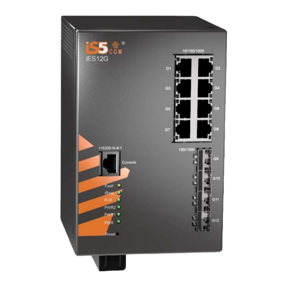
User’s Manual HARDWARE OVERVIEW 2.1 Front Panel The iES12G hardware overview is as follows: Description Specification 8 X 10/100/1000Base-T(X) RJ45 Auto MDI/MDIX 4 X 100/1000Base-X SFP RS-232 with RJ45 connector with console cable: 115200 bps, 8, N, 1 RS-232 Serial Console Port Figure 1 –... -
Page 20: 2.2 Front Panel Led
This cover must be re-attached after wiring to ensure personnel safety. The iES12G series supports dual redundant power supplies (PWR1 and PWR2). There are 3 options: •... -
Page 21: Figure 2 - Bottom View Of Panel
Connect to the (Neutral) terminal of Power supply 2 the second or backup DC power source. RLY NO Failsafe Relay, (Normally Open) contact. RLY CM Failsafe Relay (Common) contact. RLY NC Failsafe Relay (No Contact) contact. UM-iES12G-1.72.2-EN.docx Pages 10 of 166 © 2020 IS5 COMMUNICATIONS INC. ALL RIGHTS RESERVED... -
Page 22: 2.4 Rear Panel
User’s Manual Chassis Ground Connection The IES12G chassis ground connection, located next to the terminal block, uses a #6-32 Screw. We recommend terminating the ground connection using a #6 ring lug, and a torque setting of 15 in.lbs (1.7Nm). -
Page 23: 2.5 Side Panel
2.5 Side Panel The components on the side of the iES10G are shown below: 1. Screw holes (4) for wall mount kit. Figure 4 – Side Panel UM-iES12G-1.72.2-EN.docx Pages 12 of 166 © 2020 IS5 COMMUNICATIONS INC. ALL RIGHTS RESERVED... -
Page 24: Hardware Installation
Figure 5 - DIN-Rail Bracket Step 2: Push the bottom of the switch toward the DIN-Rail until the bracket snaps in place. Figure 6 - Switch Mounted on DIN-Rail UM-iES12G-1.72.2-EN.docx Pages 13 of 166 © 2020 IS5 COMMUNICATIONS INC. ALL RIGHTS RESERVED... -
Page 25: 3.2 Wall Mount Installation
The switch can also be panel or wall mounted. The following steps show how to mount the switch on a panel or wall. Mounting IES12G on a Wall or Panel Option 1: Side of switch Fix mounting brackets to the side of switch using the 4 screws included in the package. -
Page 26: 3.3 Connection
3.3 Connection Ethernet Cables The IES12G switches have standard Ethernet ports. According to the link type, the switches use CAT 3, 4, 5, and 5e UTP cables to connect to any other network device (e.g. PCs, servers, switches, routers, or hubs). -
Page 27: Sfp
LC connectors. Remember that the TX port of Switch A should be connected to the RX port of Switch B. Switch A Switch B Fiber Figure 9 – SFPs UM-iES12G-1.72.2-EN.docx Pages 16 of 166 © 2020 IS5 COMMUNICATIONS INC. ALL RIGHTS RESERVED... -
Page 28: 3.4 Console Cable
3.4 Console Cable The iES12G switch can be managed via the console port using the RS232 / DB-9 to RJ-45 cable provided. Connect to the PC via the RS-232/DB9 connector and the RJ45 connector to the console port of the switch. -
Page 29: Web Management
2. Type http:// and the switch’s IP address (default is 192.168.10.1), and then press Enter. Figure 12 – Switch’s IP Address Screen 3. The Welcome to …. screen appears. Click 4. The login screen appears (see Figure 13 – Login Screen). UM-iES12G-1.72.2-EN.docx Pages 18 of 166 © 2020 IS5 COMMUNICATIONS INC. ALL RIGHTS RESERVED... -
Page 30: Basic Setting
6. Click OK. The main interface of the Web Management appears (see Figure 14). Figure 14 – Main Interface or System Information tab Basic Setting System Information The switch system information is provided here. Figure 15 – System Information Configuration UM-iES12G-1.72.2-EN.docx Pages 19 of 166 © 2020 IS5 COMMUNICATIONS INC. ALL RIGHTS RESERVED... -
Page 31: Banner
This page allows the user to configure the System Login Banner Title and System Banner Message. The Banner appears when you are trying to access the device through WebUI or CLI. Figure 16 – System Banner Configuration UM-iES12G-1.72.2-EN.docx Pages 20 of 166 © 2020 IS5 COMMUNICATIONS INC. ALL RIGHTS RESERVED... -
Page 32: Admin Password
This page allows the user to configure the system guest password required to access the web interface or log in to the CLI. Figure 18 – Guest Password Configuration UM-iES12G-1.72.2-EN.docx Pages 21 of 166 © 2020 IS5 COMMUNICATIONS INC. ALL RIGHTS RESERVED... -
Page 33: Authentication Method
Click to undo any changes made locally and revert to previously saved values Auto Logout Configuration The Auto logout time for WebUI and CLI access can be defined by an user. UM-iES12G-1.72.2-EN.docx Pages 22 of 166 © 2020 IS5 COMMUNICATIONS INC. ALL RIGHTS RESERVED... -
Page 34: Ip Setting
The default IP is 192.168.10.1. IP M ask Provide the IP mask of this switch dotted decimal notation. IP Router Provide the IP address of the router in dotted decimal notation. UM-iES12G-1.72.2-EN.docx Pages 23 of 166 © 2020 IS5 COMMUNICATIONS INC. ALL RIGHTS RESERVED... -
Page 35: Ipv6 Setting
16- bit groups of contiguous zeros; but it can appear only once. It can also represent a legally valid IPv4 address. . For example, '::192.1.2.34'. UM-iES12G-1.72.2-EN.docx Pages 24 of 166 © 2020 IS5 COMMUNICATIONS INC. ALL RIGHTS RESERVED... -
Page 36: Ip Configuration
Provide the IPv4 address of a SNTP server. Server Address Save Click to save changes Reset Click to undo any changes made locally and revert to previously saved values UM-iES12G-1.72.2-EN.docx Pages 25 of 166 © 2020 IS5 COMMUNICATIONS INC. ALL RIGHTS RESERVED... -
Page 37: Daylight Saving Time
Date - Select the starting date. (Non-Recurring) Start Time • Year - Select the starting year. (Non-Recurring) Settings • Hours - Select the starting hour. • Minutes - Select the starting minute. UM-iES12G-1.72.2-EN.docx Pages 26 of 166 © 2020 IS5 COMMUNICATIONS INC. ALL RIGHTS RESERVED... -
Page 38: Switch Time Configuration
HTTP application layering. HTTPS encrypts and decrypts user page requests as well as the pages that are returned by the Web server. Configure HTTPS settings in the following page. Figure 26 - HTTPS Configuration UM-iES12G-1.72.2-EN.docx Pages 27 of 166 © 2020 IS5 COMMUNICATIONS INC. ALL RIGHTS RESERVED... -
Page 39: Ssh
Indicates the selected Telnet mode. The modes include: Enabled: enable telnet. Disabled: disable Telnet. Save Click to save changes. Reset Click to undo any changes made locally and revert to previously saved values. UM-iES12G-1.72.2-EN.docx Pages 28 of 166 © 2020 IS5 COMMUNICATIONS INC. ALL RIGHTS RESERVED... -
Page 40: Lldp
Enabled The switch will send out LLDP information, and will analyze LLDP information received from neighbours. LLDP Neighbor Information This page provides a status overview for all LLDP neighbors. The following table contains UM-iES12G-1.72.2-EN.docx Pages 29 of 166 © 2020 IS5 COMMUNICATIONS INC. ALL RIGHTS RESERVED... -
Page 41: Lldp Statistics
Two types of counters are shown. Global Counters are counters that refer to the whole switch, while Local Counters refer to per port counters for the currently selected switch. UM-iES12G-1.72.2-EN.docx Pages 30 of 166 © 2020 IS5 COMMUNICATIONS INC. ALL RIGHTS RESERVED... -
Page 42: Global Counters
(Type Length Value). If a TLV is malformed, it will be counted and discarded. The number of well-formed TLVs but with an unknown type value TLVs Unrecognized Org. Discarded The number of received organizationally TLVs UM-iES12G-1.72.2-EN.docx Pages 31 of 166 © 2020 IS5 COMMUNICATIONS INC. ALL RIGHTS RESERVED... -
Page 43: Modbus Tcp
This page allows the user to load a previously saved configuration to the switch. Figure 34 – Configuration Upload Firmware Update This page allows the user to update the firmware of the switch. Figure 35 – Software Upload UM-iES12G-1.72.2-EN.docx Pages 32 of 166 © 2020 IS5 COMMUNICATIONS INC. ALL RIGHTS RESERVED... -
Page 44: Dhcp Server/Relay
Click to undo any changes made locally and revert to previously saved values. DHCP Dynamic Client List When DHCP server functions are activated, the switch will collect DHCP client information and display in the following table. UM-iES12G-1.72.2-EN.docx Pages 33 of 166 © 2020 IS5 COMMUNICATIONS INC. ALL RIGHTS RESERVED... -
Page 45: Dhcp Client List
Delete selected entry. Select/Clear All Select or Clear all check boxes. Port Setting Port Setting allows managing of individual ports of the switch, including traffic, power, and trunks. UM-iES12G-1.72.2-EN.docx Pages 34 of 166 © 2020 IS5 COMMUNICATIONS INC. ALL RIGHTS RESERVED... -
Page 46: Port Control
PerfectReach: Link up power savings enabled. Enabled: Both link up and link down power savings enabled. Total Power Usage Total power usage in board, measured in percent. UM-iES12G-1.72.2-EN.docx Pages 35 of 166 © 2020 IS5 COMMUNICATIONS INC. ALL RIGHTS RESERVED... -
Page 47: Port Alias
Refresh undone. Port Trunk Configuration This page is used to configure the static link aggregation hash mode and the aggregation group. Figure 41 - Aggregation Mode Configuration UM-iES12G-1.72.2-EN.docx Pages 36 of 166 © 2020 IS5 COMMUNICATIONS INC. ALL RIGHTS RESERVED... -
Page 48: Lacp Port Configuration
Note that LACP and Static aggregation can’t be both enabled on the same ports. This page allows the user to inspect the current LACP port configurations, and possibly change them as UM-iES12G-1.72.2-EN.docx Pages 37 of 166 © 2020 IS5 COMMUNICATIONS INC. ALL RIGHTS RESERVED... -
Page 49: Lacp System Status
Reset Click to undo any changes made locally and revert to previously saved values. LACP System Status This page provides a status overview for all LACP instances. UM-iES12G-1.72.2-EN.docx Pages 38 of 166 © 2020 IS5 COMMUNICATIONS INC. ALL RIGHTS RESERVED... -
Page 50: Lacp Port Status
The partner’s port number associated with the port. Port Click to refresh the page immediately. Refresh Check to enable an automatic refresh of the page at regular intervals. Auto- refresh UM-iES12G-1.72.2-EN.docx Pages 39 of 166 © 2020 IS5 COMMUNICATIONS INC. ALL RIGHTS RESERVED... -
Page 51: Lacp Port Statistics
This page allows the user to inspect the current Loop Protection configurations, and possibly change them as well. Figure 47 – Loop Protection UM-iES12G-1.72.2-EN.docx Pages 40 of 166 © 2020 IS5 COMMUNICATIONS INC. ALL RIGHTS RESERVED... -
Page 52: Redundancy
Ring in the world. The recovery time of iRing is less than 20 ms. iRing supports 3 topologies: iRing, Binding Ring and Dual Homing. UM-iES12G-1.72.2-EN.docx Pages 41 of 166 © 2020 IS5 COMMUNICATIONS INC. ALL RIGHTS RESERVED... -
Page 53: Ichain
UM-iES12G-1.72.2-EN.docx Pages 42 of 166 © 2020 IS5 COMMUNICATIONS INC. ALL RIGHTS RESERVED... -
Page 54: Ibridge
The Rapid Spanning Tree Protocol (RSTP) is an evolution of the Spanning Tree Protocol (STP). It provides faster convergence of spanning tree after a topology change. The system also supports STP and will UM-iES12G-1.72.2-EN.docx Pages 43 of 166 © 2020 IS5 COMMUNICATIONS INC. ALL RIGHTS RESERVED... -
Page 55: Rstp Bridge Setting
2 x (Forward Delay Time value –1) ≥ Max Age value ≥ 2 x (Hello Time value +1) RSTP Port Setting This page allows the user to configure the current RSTP port configurations, and change them as well. UM-iES12G-1.72.2-EN.docx Pages 44 of 166 © 2020 IS5 COMMUNICATIONS INC. ALL RIGHTS RESERVED... -
Page 56: Figure 53 - Rstp Port Setting
Transition to the forwarding state is faster for point-to-point LANs than for shared media. Save Click to apply the configurations. Reset Click to undo any changes made locally and revert to previously saved values. UM-iES12G-1.72.2-EN.docx Pages 45 of 166 © 2020 IS5 COMMUNICATIONS INC. ALL RIGHTS RESERVED... -
Page 57: Rstp Bridge Status
It shows whether RSTP is enabled or disabled on this switch port. Port Priority Which ports should be blocked by priority in LAN. A number 0 through 240. The value of priority must be the multiple of 16. UM-iES12G-1.72.2-EN.docx Pages 46 of 166 © 2020 IS5 COMMUNICATIONS INC. ALL RIGHTS RESERVED... -
Page 58: Mstp
The maximum time the information transmitted by the root bridge is considered valid. The range of valid values is 6 to 40 seconds, and Max Age must be <= (FwdDelay-1)*2. UM-iES12G-1.72.2-EN.docx Pages 47 of 166 © 2020 IS5 COMMUNICATIONS INC. ALL RIGHTS RESERVED... -
Page 59: Msti Mapping
Internal Spanning Tree (CIST), which is the default spanning tree instance for MSTP, and the other in the context of each individual spanning tree context, that is, MSTI. [6] UM-iES12G-1.72.2-EN.docx Pages 48 of 166 © 2020 IS5 COMMUNICATIONS INC. ALL RIGHTS RESERVED... -
Page 60: Figure 57 - Msti Configuration
MSTI should just be left empty. (I.e. not having any VLANs mapped to it.) Example: 2,5,20-40. Save Click to save changes. Reset Click to undo any changes made locally and revert to previously saved values. UM-iES12G-1.72.2-EN.docx Pages 49 of 166 © 2020 IS5 COMMUNICATIONS INC. ALL RIGHTS RESERVED... -
Page 61: Msti Priorities
This page allows the user to inspect the current STP CIST port configurations, and possibly change them as well. This page contains settings for physical and aggregated ports. The aggregation settings are stack global. This page contains settings for physical and aggregated ports. UM-iES12G-1.72.2-EN.docx Pages 50 of 166 © 2020 IS5 COMMUNICATIONS INC. ALL RIGHTS RESERVED... -
Page 62: Figure 59 - Stp Msti Port Configuration
This feature is also known as Root Guard. UM-iES12G-1.72.2-EN.docx Pages 51 of 166 © 2020 IS5 COMMUNICATIONS INC. ALL RIGHTS RESERVED... -
Page 63: Msti Ports
MSTI instance configured on and applicable to the port. The MSTI instance must be selected before displaying actual MSTI port configuration options. This page contains MSTI port settings for physical and aggregated ports. UM-iES12G-1.72.2-EN.docx Pages 52 of 166 © 2020 IS5 COMMUNICATIONS INC. ALL RIGHTS RESERVED... -
Page 64: Stp Bridges
The bridge ID of this bridge instance. Root ID The bridge ID of the currently selected root bridge. Root Port The switch port currently assigned the root port role. UM-iES12G-1.72.2-EN.docx Pages 53 of 166 © 2020 IS5 COMMUNICATIONS INC. ALL RIGHTS RESERVED... -
Page 65: Stp Port Status
The time since the bridge port was last initialized Refresh Click to refresh the page immediately. Auto- Check this box to enable an automatic refresh of the page at regular intervals. refresh UM-iES12G-1.72.2-EN.docx Pages 54 of 166 © 2020 IS5 COMMUNICATIONS INC. ALL RIGHTS RESERVED... -
Page 66: Stp Statistics
The number of illegal spanning tree BPDU’s received (and discarded) on the port. Illegal Refresh Click to refresh the page immediately. Auto-refresh Check to enable an automatic refresh of the page at regular intervals. UM-iES12G-1.72.2-EN.docx Pages 55 of 166 © 2020 IS5 COMMUNICATIONS INC. ALL RIGHTS RESERVED... -
Page 67: Fast Recovery
Dual Port Recovery mode is defined to work with unmanaged devices/switches or ring of switches. This feature can be set to on single port of switches on both sides of unmanaged ring. The IES12G with Dual Port Recovery mode will provide redundant links. - Page 68 When link of port 1 on switch 2 returns back to be link up, the switch 1 port 1 is in “forwarding” state and in this case the “No Link” port is changing its status to be “Blocking” port. UM-iES12G-1.72.2-EN.docx Pages 57 of 166 © 2020 IS5 COMMUNICATIONS INC. ALL RIGHTS RESERVED...
-
Page 69: Dual Port Recovery-Configuration
Set the maximum number of lost frames to start Dual Port Recovery mechanism (1-500 Retry retries default 3 )Note: Test Max Retry should be the same on both sides. Apply Click Apply to activate the configurations. UM-iES12G-1.72.2-EN.docx Pages 58 of 166 © 2020 IS5 COMMUNICATIONS INC. ALL RIGHTS RESERVED... -
Page 70: Vlan
Click Delete to undo the addition of new VLANs. Click to save changes. Save Reset Click to undo any changes made locally and revert to previously saved values. UM-iES12G-1.72.2-EN.docx Pages 59 of 166 © 2020 IS5 COMMUNICATIONS INC. ALL RIGHTS RESERVED... -
Page 71: Example For Port-Based Vlan Setting
User’s Manual Example for Port-Based VLAN Setting For ingress port VLAN Membership Configuration setting port 1 & VID=50 VLAN Port 1 Configuration-->Disable VLAN Aware VLAN Port 1 Configuration-->Mode=specific,ID=50 UM-iES12G-1.72.2-EN.docx Pages 60 of 166 © 2020 IS5 COMMUNICATIONS INC. ALL RIGHTS RESERVED... -
Page 72: (For Egress Port)
VLAN Membership Configuration setting port 2 & VID=50 VLAN Port 2 Configuration-->don't care VLAN Aware 3. VLAN Port 2 Configuration-->Mode=specific,ID=50 (any packet can enter egress port ) UM-iES12G-1.72.2-EN.docx Pages 61 of 166 © 2020 IS5 COMMUNICATIONS INC. ALL RIGHTS RESERVED... -
Page 73: 802.1Q Access Port Setting
4.1.6.2.1.1 (For ingress port) VLAN Membership Configuration setting port & VID=50 VLAN Port Configuration-->Enable VLAN Aware VLAN Port Configuration-->Mode=specific,ID=50 4.1.6.2.1.2 For egress port VLAN Membership Configuration setting port & VID=50 UM-iES12G-1.72.2-EN.docx Pages 62 of 166 © 2020 IS5 COMMUNICATIONS INC. ALL RIGHTS RESERVED... -
Page 74: Q Trunk Port Setting (Multi-Tag)
3. VLAN Port Configuration-->Mode=specific,ID=50 (untagged & tag=50 packet can enter egress port ) 802.1Q Trunk port setting (multi-tag) 4.1.6.2.1.1 For ingress port VLAN Membership Configuration setting port & VID=11,22,33 UM-iES12G-1.72.2-EN.docx Pages 63 of 166 © 2020 IS5 COMMUNICATIONS INC. ALL RIGHTS RESERVED... - Page 75 When entering the tagged frame, only VID = 11,22,33 three kinds of packets can pass) 4.1.6.2.1.2 For egress port VLAN Membership Configuration setting port, VID=11,22,33 VLAN Port Configuration-->Enable VLAN Aware UM-iES12G-1.72.2-EN.docx Pages 64 of 166 © 2020 IS5 COMMUNICATIONS INC. ALL RIGHTS RESERVED...
- Page 76 User’s Manual VLAN Port Configuration-->Mode=none (egress port can receive tag=11,22,33 packet In addition ,only tag=11packet can enter egress port ) UM-iES12G-1.72.2-EN.docx Pages 65 of 166 © 2020 IS5 COMMUNICATIONS INC. ALL RIGHTS RESERVED...
- Page 77 4.1.6.2.1.3 For ingress port-Port 1 VLAN Membership Configuration setting port 1、2、3 & VID=50 2. VLAN Port Configuration-->Disable Port 1 VLAN Aware 3. VLAN Port Configuration-->Port 1 Mode=specific,ID=50 UM-iES12G-1.72.2-EN.docx Pages 66 of 166 © 2020 IS5 COMMUNICATIONS INC. ALL RIGHTS RESERVED...
- Page 78 4.1.6.2.1.4 For egress port -Port 2 VLAN Membership Configuration setting port & VID=50 VLAN Port Configuration-->Enable Port 2、3 VLAN Aware. 3. VLAN Port Configuration-->Mode=none (only tag=50 packet can enter egress port ) UM-iES12G-1.72.2-EN.docx Pages 67 of 166 © 2020 IS5 COMMUNICATIONS INC. ALL RIGHTS RESERVED...
-
Page 79: Private Vlan
A VLAN unaware port can only be a member of one VLAN, but it can be a member of multiple Private VLANs. Figure 67 – Private VLAN Membership Configuration UM-iES12G-1.72.2-EN.docx Pages 68 of 166 © 2020 IS5 COMMUNICATIONS INC. ALL RIGHTS RESERVED... -
Page 80: Port Isolation Configuration
Check this box to refresh the page automatically. Automatic refresh occurs every Auto-refresh 3 seconds. Click to save changes. Save Click to undo any changes made locally and revert to previously saved values. Reset UM-iES12G-1.72.2-EN.docx Pages 69 of 166 © 2020 IS5 COMMUNICATIONS INC. ALL RIGHTS RESERVED... -
Page 81: Snmp
Indicates the SNMPv3 engine ID. The string must contain an even number between 10 and 64 hexadecimal digits, but all-zeros and all-'F's are not allowed. Change of the Engine ID will clear all original local users. UM-iES12G-1.72.2-EN.docx Pages 70 of 166 © 2020 IS5 COMMUNICATIONS INC. ALL RIGHTS RESERVED... -
Page 82: Snmp Trap Configuration
16-bit groups of contiguous zeros; but it can appear only once. It can also represent a legally valid IPv4 address. For example, '::192.1.2.34'. UM-iES12G-1.72.2-EN.docx Pages 71 of 166 © 2020 IS5 COMMUNICATIONS INC. ALL RIGHTS RESERVED... -
Page 83: Snmp Communities Configurations
Click to undo any changes made locally and revert to previously saved values. Reset SNMP Communities Configurations This page allows the user to configure SNMPv3 community table. The entry index key is Community. Figure 71 – SNMPv3 Community Configuration UM-iES12G-1.72.2-EN.docx Pages 72 of 166 © 2020 IS5 COMMUNICATIONS INC. ALL RIGHTS RESERVED... -
Page 84: Snmp User Configurations
A string identifying the user name that this entry should belong to. The allowed string length is 1 to 32, and the allowed content is ASCII characters from 33 to 126. UM-iES12G-1.72.2-EN.docx Pages 73 of 166 © 2020 IS5 COMMUNICATIONS INC. ALL RIGHTS RESERVED... - Page 85 Privacy A string identifying the privacy pass phrase. The allowed string length is Password 8 to 32 and only ASCII characters from 33 to 126 are allowed. UM-iES12G-1.72.2-EN.docx Pages 74 of 166 © 2020 IS5 COMMUNICATIONS INC. ALL RIGHTS RESERVED...
-
Page 86: Snmp Group Configurations
SNMP Views Configurations This page allows the user to configure SNMPv3 view table. The entry index keys are View Name and OID Subtree. Figure 74 – SNMPv3 Views Configuration UM-iES12G-1.72.2-EN.docx Pages 75 of 166 © 2020 IS5 COMMUNICATIONS INC. ALL RIGHTS RESERVED... -
Page 87: Snmp Access Configurations
Indicates the security model that this entry should belong to. Possible security models include: any: Accepted any security model (v1|v2c|usm). v1: Reserved for SNMPv1. v2c: Reserved for SNMPv2c. usm: User-based Security Model (USM). UM-iES12G-1.72.2-EN.docx Pages 76 of 166 © 2020 IS5 COMMUNICATIONS INC. ALL RIGHTS RESERVED... -
Page 88: Traffic Prioritization
This page allows the user to configure the storm control settings for all switch ports. There is a storm rate control for unicast frames, broadcast frames, and unknown (flooded) frames. UM-iES12G-1.72.2-EN.docx Pages 77 of 166 © 2020 IS5 COMMUNICATIONS INC. ALL RIGHTS RESERVED... -
Page 89: Port Classification
CoS values coming in from the end points are retained in the absence of any explicit policy configuration. [9] This page allows the user to configure the basic QoS Ingress Classification settings for all switch ports. UM-iES12G-1.72.2-EN.docx Pages 78 of 166 © 2020 IS5 COMMUNICATIONS INC. ALL RIGHTS RESERVED... -
Page 90: Figure 77 - Qos Ingress Port Classification
If the port is VLAN aware and the frame is tagged, then the frame is classified to the PCP value in the tag. Otherwise the frame is classified to the default PCP value. UM-iES12G-1.72.2-EN.docx Pages 79 of 166 © 2020 IS5 COMMUNICATIONS INC. ALL RIGHTS RESERVED... -
Page 91: Port Tag Remarking
Shows the tag remarking mode for this port: Classified: use classified PCP/DEI values. Default: use default PCP/DEI values. Mapped: use mapped versions of QoS class and DP level. UM-iES12G-1.72.2-EN.docx Pages 80 of 166 © 2020 IS5 COMMUNICATIONS INC. ALL RIGHTS RESERVED... -
Page 92: Port Dscp
Remap: DSCP from the analyzer is remapped and the frame is remarked with remapped DSCP value. Click to save changes. Save Click to undo any changes made locally and revert to previously saved values. Reset UM-iES12G-1.72.2-EN.docx Pages 81 of 166 © 2020 IS5 COMMUNICATIONS INC. ALL RIGHTS RESERVED... -
Page 93: Port Policing
Click to undo any changes made locally and revert to previously saved values. Queue Policing This page allows the user to configure Queue Policer settings for all switch ports. UM-iES12G-1.72.2-EN.docx Pages 82 of 166 © 2020 IS5 COMMUNICATIONS INC. ALL RIGHTS RESERVED... -
Page 94: Port Schedulers
Click the port number to configure the schedulers. Details for configuration can be found in the QoS Egress Port Scheduler and Shapers section. Shows the scheduling mode for this port. Mode Shows the weight for this queue and port. Weight UM-iES12G-1.72.2-EN.docx Pages 83 of 166 © 2020 IS5 COMMUNICATIONS INC. ALL RIGHTS RESERVED... -
Page 95: Port Shaping
This is accessed by clicking specific port on the Port Scheduler or Shaping screen (Port 1 shown). Strict Priority In the Scheduler Mode, from the drop-down list, select Strict Priority. Figure 84 - QoS Ingress Port Scheduler and Shapers Port 1- Strict Priority UM-iES12G-1.72.2-EN.docx Pages 84 of 166 © 2020 IS5 COMMUNICATIONS INC. ALL RIGHTS RESERVED... -
Page 96: Weighted
Cancel Weighted In the Scheduler Mode, from the drop-down list, select Weighted. Figure 85 - QoS Egress Port Scheduler and Shapers Port 1 – Scheduler Mode Weighted UM-iES12G-1.72.2-EN.docx Pages 85 of 166 © 2020 IS5 COMMUNICATIONS INC. ALL RIGHTS RESERVED... -
Page 97: Dscp-Based Qos
Click to undo any changes made locally and return to the previous page. DSCP-Based QoS This page allows the user to configure basic QoS DSCP-Based QoS Ingress Classification settings for all switches. UM-iES12G-1.72.2-EN.docx Pages 86 of 166 © 2020 IS5 COMMUNICATIONS INC. ALL RIGHTS RESERVED... -
Page 98: Figure 86 - Qos Dscp-Based Qos Ingress Classification
DP level of 1 corresponds to 'Discard Eligible' (Yellow) frames Reset Click to undo any changes made locally and revert to previously saved values. UM-iES12G-1.72.2-EN.docx Pages 87 of 166 © 2020 IS5 COMMUNICATIONS INC. ALL RIGHTS RESERVED... -
Page 99: Dscp Translation
Remap DP1 Select the DSCP value from select menu to which you want to remap. DSCP value ranges form 0 to 63. Save Click to save changes. Reset Click to undo any changes made locally and revert to previously saved values. UM-iES12G-1.72.2-EN.docx Pages 88 of 166 © 2020 IS5 COMMUNICATIONS INC. ALL RIGHTS RESERVED... -
Page 100: Dscp Classification
Actual Drop Precedence Level. DSCP Select the classified DSCP value (0-63) Save Click to save changes. Reset Click to undo any changes made locally and revert to previously saved values. UM-iES12G-1.72.2-EN.docx Pages 89 of 166 © 2020 IS5 COMMUNICATIONS INC. ALL RIGHTS RESERVED... -
Page 101: Qos Control List
DMAC Type : Destination MAC type, can be unicast (UC), multicast (M C), broadcast (BC) or Any Frame Type can be values such as Any, Ethernet, LLC, SNAP, IPv4, IPv6 Frame Type Allow all types of frames UM-iES12G-1.72.2-EN.docx Pages 90 of 166 © 2020 IS5 COMMUNICATIONS INC. ALL RIGHTS RESERVED... - Page 102 Valid DSCP value can be (0-63, BE, CS1-CS7, EF or AF11-AF43) or Parameters Default. Default means that the default classified value is not modified by this QCE. UM-iES12G-1.72.2-EN.docx Pages 91 of 166 © 2020 IS5 COMMUNICATIONS INC. ALL RIGHTS RESERVED...
-
Page 103: Qos Statistics
The maximum number of QCEs is 256 on each switch . Figure 91 - QoS Control List Status Label Description User Indicates the QCL user. QCE# Indicates the index of QCE. UM-iES12G-1.72.2-EN.docx Pages 92 of 166 © 2020 IS5 COMMUNICATIONS INC. ALL RIGHTS RESERVED... - Page 104 Clear Clear all statistics counters. Auto- Check this box to refresh the page automatically. Automatic refresh occurs every 3 refresh seconds. Refresh Click to refresh the page. UM-iES12G-1.72.2-EN.docx Pages 93 of 166 © 2020 IS5 COMMUNICATIONS INC. ALL RIGHTS RESERVED...
-
Page 105: Multicast
Check to enable fast leave on the port Save Click to save changes. Reset Click to undo any changes made locally and revert to previously saved values. UM-iES12G-1.72.2-EN.docx Pages 94 of 166 © 2020 IS5 COMMUNICATIONS INC. ALL RIGHTS RESERVED... -
Page 106: Igmp Snooping Vlan Configurations
Click to add a new entry into the table. IGMP VLAN Click to save changes. Save Click to undo any changes made locally and revert to previously saved values. Reset UM-iES12G-1.72.2-EN.docx Pages 95 of 166 © 2020 IS5 COMMUNICATIONS INC. ALL RIGHTS RESERVED... -
Page 107: Igmp Snooping Status
Check to enable an automatic refresh of the page at regular intervals. Router Port Port number on the switch. Router Port Status Indicates whether a specific port is a router port or not UM-iES12G-1.72.2-EN.docx Pages 96 of 166 © 2020 IS5 COMMUNICATIONS INC. ALL RIGHTS RESERVED... -
Page 108: Igmp Snooping Group Information
Updates the table, starting with the first entry in the IGMP Group Table. >> Updates the table, starting with the entry after the last entry currently displayed. UM-iES12G-1.72.2-EN.docx Pages 97 of 166 © 2020 IS5 COMMUNICATIONS INC. ALL RIGHTS RESERVED... -
Page 109: Remote Control Security
— Alive Check, Stream Check, and DoS/DDoS auto-prevention. This page provides Device Binding related configuration. Figure 97 - Device Binding UM-iES12G-1.72.2-EN.docx Pages 98 of 166 © 2020 IS5 COMMUNICATIONS INC. ALL RIGHTS RESERVED... - Page 110 Indicates the DDOS Prevention status. Possible options are: DDOS ---: Disable. Prevention Analysing: Analyse the packet throughput for initialization. Status Running: Function ready. Attacked: DDOS attack happened. Click to save changes. Save UM-iES12G-1.72.2-EN.docx Pages 99 of 166 © 2020 IS5 COMMUNICATIONS INC. ALL RIGHTS RESERVED...
-
Page 111: Advanced Configurations
Link Change: Link down the port, and link up once. Action Only Log it Shunt Down the Port: Shut down the port(No Link), and log the event. Only Log it: Just log the event. UM-iES12G-1.72.2-EN.docx Pages 100 of 166 © 2020 IS5 COMMUNICATIONS INC. ALL RIGHTS RESERVED... -
Page 112: Ddos Prevention
In this case, Number please insert the same number. If packet type is UDP (or TCP), please choose the socket direction (Destination / Filter Source). UM-iES12G-1.72.2-EN.docx Pages 101 of 166 © 2020 IS5 COMMUNICATIONS INC. ALL RIGHTS RESERVED... -
Page 113: Device Description
Phone, Access Point, PC, PLC, and Network Video Recorder Indicates location information of the device. The information can be used for Location Address Google Mapping. Description Device descriptions UM-iES12G-1.72.2-EN.docx Pages 102 of 166 © 2020 IS5 COMMUNICATIONS INC. ALL RIGHTS RESERVED... -
Page 114: Stream Check
---: no action Log it: simply logs the event Indicates the Stream Check status. Possible statuses are: ---: disables Stream Check Status Normal: Stream Check is enabled UM-iES12G-1.72.2-EN.docx Pages 103 of 166 © 2020 IS5 COMMUNICATIONS INC. ALL RIGHTS RESERVED... -
Page 115: Acl
Specifies the shutdown operation of this port. The allowed values are: Enabled: if a frame is received on the port, the port will be disabled. Shutdown Disabled: port shut down is disabled. The default value is Disabled. UM-iES12G-1.72.2-EN.docx Pages 104 of 166 © 2020 IS5 COMMUNICATIONS INC. ALL RIGHTS RESERVED... -
Page 116: Rate Limiters
Unit kbps: Kbits per second. Click to save changes. Save Click to undo any changes made locally and revert to previously saved values. Reset UM-iES12G-1.72.2-EN.docx Pages 105 of 166 © 2020 IS5 COMMUNICATIONS INC. ALL RIGHTS RESERVED... -
Page 117: Access Control List
First select the Ingress Port for the ACE, and then select the frame type. Different parameter options are displayed depending on the frame type selected. A frame that hits this ACE matches the configuration that is defined here. UM-iES12G-1.72.2-EN.docx Pages 106 of 166 © 2020 IS5 COMMUNICATIONS INC. ALL RIGHTS RESERVED... -
Page 118: Figure 107 - Ace Configuration
Disabled indicates that the port Port redirect operation is disabled and the specific port number of 'Port Redirect' can't be set Redirect when action is permitted. UM-iES12G-1.72.2-EN.docx Pages 107 of 166 © 2020 IS5 COMMUNICATIONS INC. ALL RIGHTS RESERVED... -
Page 119: Mac Parameters
Specify whether frames can hit the action according to the 802.1Q tagged. The allowed values are: Any: Any value is allowed ("don't-care"). 802.1Q Enabled: Tagged frame only. Tagged Disabled: Untagged frame only. The default value is Any. UM-iES12G-1.72.2-EN.docx Pages 108 of 166 © 2020 IS5 COMMUNICATIONS INC. ALL RIGHTS RESERVED... -
Page 120: Ip Parameters
Any means that no tag priority is specified (tag priority is "don't-care"). IP Parameters Figure 110 - IP Parameters The IP parameters can be configured when Frame Type of IPv4 is selected (see Figure 107 - ACE Configuration). UM-iES12G-1.72.2-EN.docx Pages 109 of 166 © 2020 IS5 COMMUNICATIONS INC. ALL RIGHTS RESERVED... - Page 121 IP mask in the SIP Address and SIP Mask fields that appear. When Host or Network is selected for the source IP filter, you can enter a specific SIP address in dotted decimal notation. Address UM-iES12G-1.72.2-EN.docx Pages 110 of 166 © 2020 IS5 COMMUNICATIONS INC. ALL RIGHTS RESERVED...
-
Page 122: Arp Parameters
DIP M ask in dotted decimal notation. ARP Parameters The ARP parameters can be configured when Frame Type of ARP is selected (see below). Figure 111 - ARP Parameters UM-iES12G-1.72.2-EN.docx Pages 111 of 166 © 2020 IS5 COMMUNICATIONS INC. ALL RIGHTS RESERVED... - Page 123 0: ARP frames where SHA is not equal to the SMAC address MAC Match 1: ARP frames where SHA is equal to the SMAC address Any: any value is allowed ("don't-care "). UM-iES12G-1.72.2-EN.docx Pages 112 of 166 © 2020 IS5 COMMUNICATIONS INC. ALL RIGHTS RESERVED...
-
Page 124: Icmp Parameters
ICMP Parameters ICMP Parameters can be configured when: • Frame Type is IPv4 • IP Protocol Filter is Internet Control Message Protocol (ICMP) Figure 112 - ICMP Parameters UM-iES12G-1.72.2-EN.docx Pages 113 of 166 © 2020 IS5 COMMUNICATIONS INC. ALL RIGHTS RESERVED... -
Page 125: Tcp /Udp Parameters
TCP Parameters can be configured when IP Protocol Filter is set to TCP. Similarly, UDP Parameters can be configured when IP Protocol Filter is set to UDP. UM-iES12G-1.72.2-EN.docx Pages 114 of 166 © 2020 IS5 COMMUNICATIONS INC. ALL RIGHTS RESERVED... - Page 126 0: TCP frames where the FIN field is set must not be able to match this entry. TCP FIN 1: TCP frames where the FIN field is set must be able to match this entry. Any: any value is allowed ("don't-care "). UM-iES12G-1.72.2-EN.docx Pages 115 of 166 © 2020 IS5 COMMUNICATIONS INC. ALL RIGHTS RESERVED...
-
Page 127: Ethernet Type Parameters
Ethernet value. The allowed range is 0x600 to 0xFFFF but excluding 0x800(IPv4), 0x806(ARP) Type Value and 0x86DD(IPv6). A frame that hits this ACE matches this EtherType value. UM-iES12G-1.72.2-EN.docx Pages 116 of 166 © 2020 IS5 COMMUNICATIONS INC. ALL RIGHTS RESERVED... -
Page 128: Acl Status
The counter indicates the number of times the ACE was hit by a frame. Indicates the hardware status of the specific ACE. The specific ACE is not applied to the Conflict hardware due to hardware limitations. UM-iES12G-1.72.2-EN.docx Pages 117 of 166 © 2020 IS5 COMMUNICATIONS INC. ALL RIGHTS RESERVED... -
Page 129: Aaa
If a reply is not received within the subinterval, the request is transmitted again. This algorithm causes the RADIUS server to be queried up to 3 times before it is considered to be dead. UM-iES12G-1.72.2-EN.docx Pages 118 of 166 © 2020 IS5 COMMUNICATIONS INC. ALL RIGHTS RESERVED... -
Page 130: Figure 117 - Radius Authentication Server Configuration
Enable the RADIUS Accounting Server by checking this box The IP address of the RADIUS Authentication Server. IP address is expressed in dotted IP Address decimal notation. UM-iES12G-1.72.2-EN.docx Pages 119 of 166 © 2020 IS5 COMMUNICATIONS INC. ALL RIGHTS RESERVED... -
Page 131: Radius Overview
This state is only reachable when more than one server is enabled. Refresh Click to refresh the page immediately. Auto- Check to enable an automatic refresh of the page at regular intervals. refresh UM-iES12G-1.72.2-EN.docx Pages 120 of 166 © 2020 IS5 COMMUNICATIONS INC. ALL RIGHTS RESERVED... -
Page 132: Radius Details
RFC4668 - RADIUS Authentication Client MIB. [3] Use the server select box to switch between the backend servers to show details for. Figure 121 - Radius Authentication Statistics for Server #1 UM-iES12G-1.72.2-EN.docx Pages 121 of 166 © 2020 IS5 COMMUNICATIONS INC. ALL RIGHTS RESERVED... - Page 133 The number of RADIUS Access-Request packets Access radiusAuthClientExt sent to the server. This does not include Requests AccessRequests retransmissions. Access radiusAuthClientExt The number of RADIUS Access-Request packets UM-iES12G-1.72.2-EN.docx Pages 122 of 166 © 2020 IS5 COMMUNICATIONS INC. ALL RIGHTS RESERVED...
- Page 134 RADIUS authentication server. The Time granularity of this measurement is 100 ms. A value of 0 ms indicates that there hasn't been round-trip communication with the server yet. UM-iES12G-1.72.2-EN.docx Pages 123 of 166 © 2020 IS5 COMMUNICATIONS INC. ALL RIGHTS RESERVED...
-
Page 135: Figure 122 - Radius Accounting Statistics For Server #1
The number of RADIUS packets sent to the server. Requests radiusAccClientExtRequests This does not include retransmissions. The number of RADIUS Retransmissions radiusAccClientExtRetransmissions packets retransmitted to the RADIUS accounting server. UM-iES12G-1.72.2-EN.docx Pages 124 of 166 © 2020 IS5 COMMUNICATIONS INC. ALL RIGHTS RESERVED... - Page 136 3 seconds. Click to refresh the page immediately. Refresh Clears the counters for the selected server. The "Pending Requests" counter Clear will not be cleared by this operation. UM-iES12G-1.72.2-EN.docx Pages 125 of 166 © 2020 IS5 COMMUNICATIONS INC. ALL RIGHTS RESERVED...
-
Page 137: Nas (802.1X)
This scenario will loop forever. Therefore, the server timeout should be smaller than the supplicant's EAPOL Start frame retransmission rate. UM-iES12G-1.72.2-EN.docx Pages 126 of 166 © 2020 IS5 COMMUNICATIONS INC. ALL RIGHTS RESERVED... -
Page 138: Overview Of Mac-Based Authentication
RADIUS user can be used by anyone, and only the MD5-Challenge method is supported. 802.1x and MAC-Based authentication configurations consist of two sections: system- and port wide. Figure 123 - Network Access Server Configuration UM-iES12G-1.72.2-EN.docx Pages 127 of 166 © 2020 IS5 COMMUNICATIONS INC. ALL RIGHTS RESERVED... -
Page 139: System Configuration
The switch will ignore new frames coming from the client during the hold time. The hold time can be set to a number between 10 and 1000000 seconds. UM-iES12G-1.72.2-EN.docx Pages 128 of 166 © 2020 IS5 COMMUNICATIONS INC. ALL RIGHTS RESERVED... -
Page 140: Port Configuration
X seconds (using the AAA configuration page), and suppose that the first server in the list is currently down (but not considered dead). Now, if the UM-iES12G-1.72.2-EN.docx Pages 129 of 166 © 2020 IS5 COMMUNICATIONS INC. ALL RIGHTS RESERVED... - Page 141 Reinitialize: forces a reinitialization of the clients on the port and hence a reauthentication immediately. The clients will transfer to the unauthorized state while the reauthentication is in progress. UM-iES12G-1.72.2-EN.docx Pages 130 of 166 © 2020 IS5 COMMUNICATIONS INC. ALL RIGHTS RESERVED...
-
Page 142: Nas Switch
Note that Port counters are shown only for ports with Authorized port state such Port 20 (refer to Figure 125- Network Access Server Switch Status). Port 1 does not show Port counters. UM-iES12G-1.72.2-EN.docx Pages 131 of 166 © 2020 IS5 COMMUNICATIONS INC. ALL RIGHTS RESERVED... -
Page 143: Figure 126 - Nat Statistics Admin State Force Authorized
Click to refresh the page immediately. This button is available in the following modes: • Force Authorized • Force Unauthorized Clear • 802.1X Click to clear the counters for the selected port UM-iES12G-1.72.2-EN.docx Pages 132 of 166 © 2020 IS5 COMMUNICATIONS INC. ALL RIGHTS RESERVED... -
Page 144: Eapol Counters
The number of valid EAPOL Request dot1xAuthEapolReqFrames Requests frames (other than Request Identity frames) that have been transmitted by the switch. UM-iES12G-1.72.2-EN.docx Pages 133 of 166 © 2020 IS5 COMMUNICATIONS INC. ALL RIGHTS RESERVED... -
Page 145: Backend Server Counters
"Last Client" will not be cleared, however. This button is available in the following modes: Clear This • MAC-based Auth.X Click to clear only the currently selected client's counters. UM-iES12G-1.72.2-EN.docx Pages 134 of 166 © 2020 IS5 COMMUNICATIONS INC. ALL RIGHTS RESERVED... - Page 146 Counts all the backend server packets sent from the switch towards the backend server for a given port (left-most table) or client (right-most table). Possible retransmissions are not counted. UM-iES12G-1.72.2-EN.docx Pages 135 of 166 © 2020 IS5 COMMUNICATIONS INC. ALL RIGHTS RESERVED...
-
Page 147: Last Supplicant/ Client Info
802.1X-based: The user name (supplicant identity) carried in the Identity most recently received Response Identity EAPOL frame. MAC-based: Not applicable (as shown on Figure 129). Figure 130 - Last Supplicant/ Client Info Admin State 802.1X-based. UM-iES12G-1.72.2-EN.docx Pages 136 of 166 © 2020 IS5 COMMUNICATIONS INC. ALL RIGHTS RESERVED... -
Page 148: Selected Counters And Attached Clients
When any selected fault event happens, the Fault LED on the switch panel will light up and the electric relay will signal at the same time. Select the events to cause the fault alarm, then click Save, to save the UM-iES12G-1.72.2-EN.docx Pages 137 of 166 © 2020 IS5 COMMUNICATIONS INC. ALL RIGHTS RESERVED... -
Page 149: System Warning
Indicates the IPv4 host address of syslog server. If the switch provide s DNS functions, it Server also can be a host name. Address Save Click to save changes. UM-iES12G-1.72.2-EN.docx Pages 138 of 166 © 2020 IS5 COMMUNICATIONS INC. ALL RIGHTS RESERVED... -
Page 150: Smtp Settings
Password: the authentication password Confirm Password: re-enter password Recipient E-mail The recipient’s e-mail address, allows a total number of six recipients. Address Save Click to save changes UM-iES12G-1.72.2-EN.docx Pages 139 of 166 © 2020 IS5 COMMUNICATIONS INC. ALL RIGHTS RESERVED... -
Page 151: Event Selection
Label Description Alerts when the system is restarted. System Start Alerts when power is up or down. Power Status Alerts when SNMP authentication fails. SNMP Authentication Failure UM-iES12G-1.72.2-EN.docx Pages 140 of 166 © 2020 IS5 COMMUNICATIONS INC. ALL RIGHTS RESERVED... -
Page 152: 4.3 Monitor And Diagnostic
The MAC address table can be configured on this page. Set timeouts for entries in the dynamic MAC table and configure the static MAC table here. Figure 136 - MAC Address Table Configuration UM-iES12G-1.72.2-EN.docx Pages 141 of 166 © 2020 IS5 COMMUNICATIONS INC. ALL RIGHTS RESERVED... -
Page 153: Aging Configuration
M AC Address The MAC address for the entry. Port Members Checkmarks indicate which ports are members of the entry. Check or uncheck to modify the entry. UM-iES12G-1.72.2-EN.docx Pages 142 of 166 © 2020 IS5 COMMUNICATIONS INC. ALL RIGHTS RESERVED... -
Page 154: Mirroring
Note: For a given port, a frame is only transmitted once. It is therefore not possible to mirror port Tx frames. Because of this, the Mode for the selected mirror port (which in the Figure above is Port 1) is limited to Disabled or Rx only. UM-iES12G-1.72.2-EN.docx Pages 143 of 166 © 2020 IS5 COMMUNICATIONS INC. ALL RIGHTS RESERVED... -
Page 155: System Log Information
Updates system log entries, ending at the last entry currently << displayed. Updates system log entries, starting from the last entry currently >> displayed. >>| Updates system log entries, ending at the last available entry ID. UM-iES12G-1.72.2-EN.docx Pages 144 of 166 © 2020 IS5 COMMUNICATIONS INC. ALL RIGHTS RESERVED... -
Page 156: Traffic Overview
The displayed counters include the total number for receive and transmit, the size for receive and transmit, and the errors for receive and transmit. UM-iES12G-1.72.2-EN.docx Pages 145 of 166 © 2020 IS5 COMMUNICATIONS INC. ALL RIGHTS RESERVED... -
Page 157: Ping
(ICMP) echo request packets to the target host and waiting for an ICMP echo reply. This page allows the user to issue ICMP packets to troubleshoot IP connectivity issues. UM-iES12G-1.72.2-EN.docx Pages 146 of 166 © 2020 IS5 COMMUNICATIONS INC. ALL RIGHTS RESERVED... -
Page 158: Veriphy Cable Diagnostics
10 and 100 Mbps ports will be linked down while running VeriPHY. Therefore, running VeriPHY on a 10 or 100 Mbps management port will cause the switch to stop responding until VeriPHY is complete. This page allows the user to perform VeriPHY cable diagnostics. UM-iES12G-1.72.2-EN.docx Pages 147 of 166 © 2020 IS5 COMMUNICATIONS INC. ALL RIGHTS RESERVED... -
Page 159: Figure 143 - Veriphy Cable Diagnostics
• Cross C - Abnormal cross-pair coupling with pair C • Cross D - Abnormal cross-pair coupling with pair D Length: the length (in meters) of the cable pair UM-iES12G-1.72.2-EN.docx Pages 148 of 166 © 2020 IS5 COMMUNICATIONS INC. ALL RIGHTS RESERVED... -
Page 160: Sfp Monitor
This page allows the user to issue ICMPv6 Ping packets to troubleshoot IP connectivity issues. Figure 145 – ICMPv6 Ping Label Description IP Address The destination IP Address UM-iES12G-1.72.2-EN.docx Pages 149 of 166 © 2020 IS5 COMMUNICATIONS INC. ALL RIGHTS RESERVED... -
Page 161: 4.4 Synchronization
False: disable external VCXO rate adjustment Clock The box allows the user to set clock frequency. Frequency The range of values is 1 - 25000000 (1 - 25MHz). UM-iES12G-1.72.2-EN.docx Pages 150 of 166 © 2020 IS5 COMMUNICATIONS INC. ALL RIGHTS RESERVED... -
Page 162: Ptp Clock Configurations
0 to 7. Add New Click to create a new clock instance. PTP Clock Save Click to save the page immediately. Reset Click to reset the page immediately. UM-iES12G-1.72.2-EN.docx Pages 151 of 166 © 2020 IS5 COMMUNICATIONS INC. ALL RIGHTS RESERVED... -
Page 163: Status
This page allows the user to examine the current PTP clock settings. For information on this screen, see Synchronization Configuration above. Figure 148 - PTP External Clock Mode and PTP Clock Configuration UM-iES12G-1.72.2-EN.docx Pages 152 of 166 © 2020 IS5 COMMUNICATIONS INC. ALL RIGHTS RESERVED... -
Page 164: 4.5 Factory Defaults
Figure 150 - System Reboot - Restart Device Label Description Click to reboot device. Click to return to the System Information page without rebooting. UM-iES12G-1.72.2-EN.docx Pages 153 of 166 © 2020 IS5 COMMUNICATIONS INC. ALL RIGHTS RESERVED... -
Page 165: Cli Management
User’s Manual CLI MANAGEMENT 5.1 About CLI Management Along with WEB-based management, the iES12G also supports Command Line Interface (CLI) management. For CLI management, console or Telnet can be used. 5.2 Command Line Interface Setup CLI Management by RS-232 Serial Console (115200, 8, none, 1,... -
Page 166: Figure 152 - Tera Term Vt, Serial Port Setup
4. Press “Enter” for the Console login screen to appear. Use the keyboard to enter the Console Username and Password which is same as for Web management (admin for both), then press “Enter”. Figure 153 - IES12G Command Line Interface - Tera Term VT 5. Start entering CLI commands at the command prompt. UM-iES12G-1.72.2-EN.docx Pages 155 of 166 ©... -
Page 167: Cli Management By Telnet
The Console login screen appears. Use the keyboard to enter the Console Username and Password, then press “Enter”. This is the same as the Web Browser password. The default Username is “admin” and the default Password is “admin”. Figure 155 - IES12G Command Line Interface - Telnet UM-iES12G-1.72.2-EN.docx Pages 156 of 166... -
Page 168: Command Groups
Type '<command> ?' to get help on a command, e.g. 'port mode ?'. Commands may be abbreviated, e.g. 'por co' instead of 'port configuration'. > Figure 156 - Command Groups Printout UM-iES12G-1.72.2-EN.docx Pages 157 of 166 © 2020 IS5 COMMUNICATIONS INC. ALL RIGHTS RESERVED... -
Page 169: Command Groups Details
[<secret>] [<server_port>] Client [console|telnet|ssh|web] [none|local|radius] [enable|disable] Statistics [<server_index>] Port Configuration [<port_list>] State [<port_list>] [enable|disable] Mode [<port_list>] [10hdx|10fdx|100hdx|100fdx|1000fdx|auto] Port> Flow Control [<port_list>] [enable|disable] MaxFrame [<port_list>] [<max_frame>] Power [<port_list>] [enable|disable|actiphy|dynamic] UM-iES12G-1.72.2-EN.docx Pages 158 of 166 © 2020 IS5 COMMUNICATIONS INC. ALL RIGHTS RESERVED... - Page 170 Msti Add <msti> <vid> Port Configuration [<port_list>] Port Mode [<port_list>] [enable|disable] Port Edge [<port_list>] [enable|disable] Port AutoEdge [<port_list>] [enable|disable] Port P2P [<port_list>] [enable|disable|auto] Port RestrictedRole [<port_list>] [enable|disable] UM-iES12G-1.72.2-EN.docx Pages 159 of 166 © 2020 IS5 COMMUNICATIONS INC. ALL RIGHTS RESERVED...
- Page 171 Router [<port_list>] [enable|disable] Flooding [enable|disable] Groups [<vid>] Status [<vid>] LLDP Configuration [<port_list>] Mode [<port_list>] [enable|disable|rx|tx] Optional_TLV [<port_list>][port_descr|sys_name|sys_descr|sys_capa|mgmt_addr] [enable|disable] Interval [<interval>] LLDP> Hold [<hold>] Delay [<delay>] Reinit [<reinit>] Info [<port_list>] UM-iES12G-1.72.2-EN.docx Pages 160 of 166 © 2020 IS5 COMMUNICATIONS INC. ALL RIGHTS RESERVED...
- Page 172 QCL Add [<qcl_id>] [<qce_id>] [<qce_id_next>] (etype <etype>) | (vid <vid>) | QoS> (port <udp_tcp_port>) | (dscp <dscp>) | (tos <tos_list>) | (tag_prio <tag_prio_list>) <class> QCL Delete <qcl_id> <qce_id> UM-iES12G-1.72.2-EN.docx Pages 161 of 166 © 2020 IS5 COMMUNICATIONS INC. ALL RIGHTS RESERVED...
- Page 173 Config> Load <ip_server> <file_name> [check] SNMP Trap Inform Retry Times [<retries>] Trap Probe Security Engine ID [enable|disable] SNMP> Trap Security Engine ID [<engineid>] Trap Security Name [<security_name>] UM-iES12G-1.72.2-EN.docx Pages 162 of 166 © 2020 IS5 COMMUNICATIONS INC. ALL RIGHTS RESERVED...
- Page 174 Load <ip_addr_string> <file_name> Firmware> Fault Alarm PortLinkDown [<port_list>] [enable|disable] Fault> Alarm PowerFailure [pwr1|pwr2|pwr3] [enable|disable] SFLOW mode [enable|disable] version [v2|v5] rate [<integer>] interval [<integer>] SFLOW> coladdr [<ip_addr>] colport [<integer>] show UM-iES12G-1.72.2-EN.docx Pages 163 of 166 © 2020 IS5 COMMUNICATIONS INC. ALL RIGHTS RESERVED...
-
Page 175: Technical Specifications
VLAN (802.1 Q) for segregation and securing network traffic • SNMPv3 authentication and privacy encryption • HTTPS / SSH v2 enhanced network security • Web and CLI authentication and authorization UM-iES12G-1.72.2-EN.docx Pages 164 of 166 © 2020 IS5 COMMUNICATIONS INC. ALL RIGHTS RESERVED... - Page 176 Single 10-48VDC Backup 22 Watts Power Consumption (Typ.) Present Overload Current Protection Internal Reverse Polarity Protection For dimensions, refer to the latest revision of the products datasheet: https://is5com.com/products/ UM-iES12G-1.72.2-EN.docx Pages 165 of 166 © 2020 IS5 COMMUNICATIONS INC. ALL RIGHTS RESERVED...
-
Page 177: Appendix A: Ies12G Modbus Information
Value :0x0000 10M‐Half 0x0001 10M‐Full 0x0002 100M‐Half 0x0003 100M‐Full 0x0004 1G‐Half 0x0005 1G‐Full 0xffff NoPort 4608 PortFlowCtrl : Port :1~VTSS_PORTS Value :0x0000 Off 0x0001 On 0xffff NoPort UM-iES12G-1.72.2-EN.docx Pages 166 of 166 © 2020 IS5 COMMUNICATIONS INC. ALL RIGHTS RESERVED...
Need help?
Do you have a question about the IES12G and is the answer not in the manual?
Questions and answers