
Related Manuals for IS5 COMMUNICATIONS iES28TG


Summary of Contents for IS5 COMMUNICATIONS iES28TG
- Page 1 User’s Manual Intelligent 28 Port Configurable Gigabit Ethernet Switch with 10GE Version 4.4 May 2017...
-
Page 2: Copyright Notice
User Manual COPYRIGHT NOTICE Copyright © 2013 iS5 Communications Inc. All rights reserved. No part of this publication may be reproduced in any form without the prior written consent of iS5 Communications Inc. (iS5). TRADEMARKS iS5Com is a registered trademark of iS5. All other trademarks belong to their respective owners. -
Page 3: Table Of Contents
2.1.3 LED ..........................14 Rear Panel ........................15 Hardware Installation ....................16 Rack-mount Installation for iES28GF ................16 Rack-mount Installation for iES28TG ................17 Module Installation (iES28TG only) ................... 18 3.3.1 RJ-45 Module ......................... 18 3.3.2 SFP Module ........................18 3.3.3... - Page 4 User Manual 4.1.2 Configurations ........................ 28 iChain ..........................30 4.2.1 Introduction ........................30 4.2.2 Configurations ........................ 30 STP/RSTP/MSTP ......................31 4.3.1 STP/RSTP ........................31 4.3.2 MSTP ..........................34 4.3.3 CIST ..........................37 MRP (Note: Feature Available by request) ..............40 4.4.1...
- Page 5 User Manual 5.3.3 Loop Protection ......................67 Redundancy ........................68 5.4.1 MRP (NOTE: Feature available by request) ............... 68 5.4.2 iRing ..........................69 5.4.3 iChain ..........................70 5.4.4 iBridge ........................... 71 5.4.5 RSTP ..........................71 5.4.6 MSTP ..........................74 5.4.7...
- Page 6 Command Line Interface Management ................184 CLI Management by RS-232 Serial Console (115200, 8, none, 1, none) ..........184 CLI M anagement by Telnet ......................186 Command Groups ........................187 Technical Specifications ..................203 Appendix A: iES28TG/GF Modbus Information ............ 205 iS5 Communications Inc.
-
Page 7: Fcc Statement And Cautions
This product contains no user-serviceable parts. Attempted service by unauthorized personnel shall render all warranties null and void. Changes or modifications not expressly approved by iS5 Communications Inc. could invalidate specifications, test results, and agency approvals, and void the user's authority to operate the equipment. -
Page 8: Getting Started
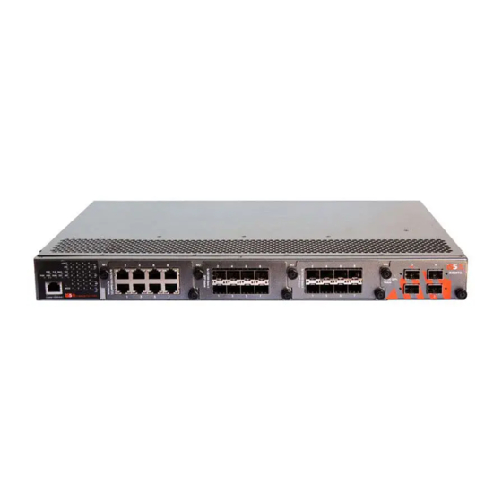
Started 1.1 About iES28TG/iES28GF The iES28Tg and the iES28GF are similar in features. The iES28TG is a fully modular rack-mount Ethernet switch with 4x10GE Uplink ports and hot-swappable power supply modules. It is optimized for harsh environments and is fully certified to IEC 61850 ed.2 standards. The iES28GF is also modular, but modules are fixed including the power supplies and i t d o e s not support 10GE uplinks. -
Page 9: Hardware Specifications
Supports 3 x 100/1000Base-X SFP modules for up to 24 ports. Supports 1 x 4 1000Base-X SFP module (iES28GF only slot 4) Supports 1 x 10G SFP+ module with up to 4 ports. (iES28TG only slot 4) Operating temperature: -40... -
Page 10: Hardware Overview
User Manual ardware Overview 2.1 Front Panel 2.1.1 Ports and Connectors The iES28TG switches provide one, 10 Gigabit module slot and three 10/100/1000Base-X slots to enable different modular combinations based on your needs. The iES28TG includes the following models. Models Description... - Page 11 User Manual CM28-2SMSC-60 MODULE - 2 x 100FX Singlemode SC, 60Km, 1310nm CM28-4SMSC-60 MODULE - 4 x 100FX Singlemode SC, 60Km, 1310nm CM28-2SMST-60 MODULE - 2 x 100FX Singlemode ST, 60Km, 1310nm CM28-4SMST-60 MODULE - 4 x 100FX Singlemode ST, 60Km, 1310nm...
-
Page 12: Ports And Connectors (Ies28Gf)
User Manual CM28-2GSMSC-40 MODULE - 2 x 1000LX Singlemode SC, 40Km, 1310nm CM28=4GSMSC-40 MODULE - 4 x 1000LX Singlemode SC, 40Km, 1310nm CM28-2GSMST-40 MODULE - 2 x 1000LX Singlemode ST, 40Km, 1310nm CM28-4GSMST-40 MODULE - 4 x 1000LX Singlemode ST, 40Km, 1310nm... - Page 13 User Manual 2SMSC15 2 x 100FX Singlemode SC, 15Km, 1310nm 4SMSC15 4 x 100FX Singlemode SC, 15Km, 1310nm 2SMST15 2 x 100FX Singlemode ST, 15Km, 1310nm 4SMST15 4 x 100FX Singlemode ST, 15Km, 1310nm 2SMSC40 2 x 100FX Singlemode SC, 40Km, 1310nm...
-
Page 14: Led
User Manual 1. System LED’s: PWR/PWR1/PWR2/R.M/Ring/Fault/DEF. 2. Port status LEDs: LINK/SPD/FDX/port number. 3. Console port. 4. Buttons: Rest/LED Mode (Press Reset for 3 seconds to reset and 5 seconds to return to factory default. To change port LED mode, press the Mode button) 5. -
Page 15: Rear Panel
User Manual 2.2 Rear Panel The two slots at the rear of the switch are for the hot-swappable power supply modules. The power supply terminal block can be mounted in the front of the chassis or at the rear as shown. The terminal block includes two power input pairs for redundant power supplies. -
Page 16: Hardware Installation
User Manual ardware Installation 3.1 Rack-mount Installation for iES28GF The switch c a n b e rack-mounted using the hardware provided. To mount the switch: Step 1: Install left and right front mounting brackets to the switch using 4 M3 screws on each side (screws provided with the switch). -
Page 17: Rack-Mount Installation For Ies28Tg
User Manual 3.2 Rack-mount Installation for iES28TG The switch can be rack-mounted using the hardware provided. iS5 Communications Inc. -
Page 18: Module Installation (Ies28Tg Only)
3.3 Module Installation (iES28TG only) 3.3.1 RJ-45 Module The iES28TG supports maximum of 3 8x10/100/1000Base T(X) configurable modules. Follow the steps below for installation. Step 1: Turn off the power to the switch. Step 2: Insert the modules in Slot 1, 2, and 3 respectively. -
Page 19: Sfp+ Module
User Manual 3.3.3 10G SFP+ Module The iES28TG supports one 10G SFP+ module, with a total of 4x10G ports. Follow the steps below for installation. Follow the steps below for installation. Step 1: Turn off the power to the switch. -
Page 20: Power Module
User Manual 3.3.4 Power Module The iES28TG supports a maximum of two power modules. Follow the steps below for installation. Step 1: Turn off the power to the switch. Step 2: Insert the modules in Power 1 and 2 slots respectively. -
Page 21: Grounding
3.3.2 Power Inputs The iES28TG supports dual redundant, hot swappable power supplies, Power Supply 1 (PWR1) and Power Supply 2 (PWR2). The connections for PWR1 and PWR2 are located on the terminal block. To connect power, follow the steps below: 1. -
Page 22: Fault Relay
Cables 1000/100BASE-TX/10BASE-T Pin Assignments The iES28TG comes with standard Ethernet ports. According to the link type, the switch uses CAT 3, 4, 5,5e UTP cables to connect to any other network device s (PCs, servers, switches, routers, or hubs). Please refer to the following table for cable specifications. - Page 23 BI_DC- BI_DB- BI_DD+ BI_DD- The iES28TG supports auto MDI/MDI- X operation. You can use a cable to connect the switch to a PC. The table below shows the 10BASE-T/ 100BASE-TX MDI and MDI- X port pin outs. iS5 Communications Inc.
- Page 24 Note: “+” and “-” signs represent the polarity of the wires that make up each wire pair. RS-232 console port wiring The iES28TG can be managed via the console port using the RS-232 cable supplied with the switch. Connect the port to a PC using the RS-232 cable with a DB-9 female connector. The DB-9 female connector of the RS-232 cable should be connected the PC while the other end of the cable (RJ-45 connector) should be connected to the console port of the switch.
-
Page 25: Sfp
User Manual 3.4.2 The switch comes with fiber optical ports that can connect to other devices using SFP modules. The fiber optical ports are multi-mode or single-mode with LC connectors. Please remember that the TX port of Switch A should be connected to the RX port of Switch B. -
Page 26: Dual Homing
User Manual Coupling Ring If two iRing topologies exist and y ou would like to connect the rings, a coupling ring can be formed. Select two switches from each ring to be connected, for example, switch A and B from Ring 1 and switch C and D from Ring 2, then decide which port on each switch will be used as the coupling ports and then link them together. - Page 27 User Manual iChain When connecting multiple iRings to meet expansion demands; an iChain topology can be created following the steps below: 1. Select two switches from the chain (Switch A & B) that you want to connect to the iRing and connect them to the switches in the ring (Switch C &...
-
Page 28: Redundancy
User Manual Redundancy Redundancy to minimize system downtime is one of the most important concerns for industrial networking devices. iRing and iBridge feature faster recovery times compared to the existing redundancy technologies widely used in commercial applications, such as STP, RSTP, and MSTP. The proprietary redundancy technologies not only support different networking topologies, but also assure the reliability of the network. - Page 29 User Manual Label Description Check to enable iRing topology. iRing Only one ring master is allowed in a ring. However, if more than one switch is set to enable Ring Master, the switch with the lowest Ring Master MAC address will be the active ring master and the others will be backup masters.
-
Page 30: Ichain
User Manual 4.2 iChain 4.2.1 Introduction iChain is a revolutionary network redundancy technology which enhances network redundancy for any backbone network, providing ease-of-use and maximum fault-recovery times, flexibility, compatibility, and cost-effectiveness. The self-healing Ethernet technology designed for distributed and complex industrial networks enables the network to recover in less than 30 milliseconds (in full- duplex Gigabit operation) or 10 milliseconds (in full-duplex Fast Ethernet operation) for up to 250 switches if at any time a segment of the chain fails. -
Page 31: Stp/Rstp/Mstp
User Manual Label Description Check to enable iChain function Enable The first port connecting to the ring Ring Port The second port connecting to the ring Ring Port An iChain topology must begin with edge ports. The ports with a smaller... -
Page 32: Stp Statistics
User Manual The switch port currently assigned the root port role. Root Port Root path cost. For a root bridge, this is zero. For other bridges, it is the Root Cost sum of port path costs on the least cost path to the Root Bridge. - Page 33 User Manual Label Description The switch port number to which the following settings will be Port applied. The number of MSTP configuration BPDU’s received/transmitted MSTP on the port The number of RSTP configuration BPDU’s received/transmitted RSTP on the port The number of legacy STP configuration BPDU’s received/transmitted on...
-
Page 34: Mstp
User Manual Label Description The version of the STP protocol. Valid values include STP, RSTP and Protocol Version MSTP. The delay used by STP bridges to transit root and designated ports Forward Delay to forwarding (used in STP compatible mode). The range of valid values is 4 to 30 seconds. - Page 35 User Manual This page contains MSTI port settings for physical and aggregated ports. The aggregation settings are stack global. Label Description The switch port number of the corresponding STP CIST (and Port MSTI) port Configures the path cost incurred by the port. Auto will set the path cost according to the physical link speed by using the 802.1D-...
- Page 36 User Manual Mapping This page allows you to examine and change the configurations of current STP MSTI bridge instances. Label Description The name which identifies the VLAN to MSTI mapping. Bridges must share the name and revision (see below), as well as the VLAN-to-...
-
Page 37: Cist
User Manual Priority This page allows you to examine and change the configurations of current STP MSTI bridge instance priorities. Label Description The bridge instance. CIST is the default instance, which is always active. M STI Indicates bridge priority. The lower the value, the higher th e priority. - Page 38 User Manual Port Settings Label Description The switch port number to which the following settings will be Port applied. STP Enabled Check to enable STP for the port Configures the path cost incurred by the port. Auto will set the path cost according to the physical link speed by using the 802.1D-...
- Page 39 User Manual When enabled, the port will not be selected as root port for CIST or any MSTI, even if it has the best spanning tree priority vector. Such a port will be selected as an alternate port after the root port has been selected.
-
Page 40: Mrp (Note: Feature Available By Request)
User Manual 4.4 MRP (feature available upon request) 4.4.1 Introduction MRP (Media Redundancy Protocol) is an industry standard for high-availability Ethernet networks. MRP allows Ethernet switches in ring configuration to recover from failure rapidly to ensure seamless data transmission. A MRP ring (IEC 62439) can support up to 50 devices and will enable a back-up link in 80ms (adjustable to max. - Page 41 User Manual Label Description Enable Enables fast recovery mode Ports can be set to 12 priorities. Only the port with the highest priority will Port be the active port. 1 Priority is the highest. Save Click to save the configurations.
-
Page 42: Management
User Manual Management The switch can be controlled using a built-in web server that supports Internet Explorer (Internet Explorer 5.0 or above versions) and other Web browsers such as Chrome. Management and configuration of the switch can easily be done remotely. Firmware upgrades may also be done using the web browser. -
Page 43: Basic Settings
User Manual Type in the username and password. The default username and password is Admin. Click Enter or OK button, the management Web page appears. Note: Session timeout is 10 minutes. On the right hand side of the management interface it shows links to various settings. Click on the links to access the configuration pages to different functions. -
Page 44: Admin Password
User Manual Label Description An administratively assigned name for the managed node. By convention, this is the node's fully-qualified domain name. A domain name is a text string consisting of alphabets (A-Z, a-z), digits (0-9), System Name and minus sign (-). Space is not allowed to be part of the name. The first character must be an alpha character. -
Page 45: Authentication Method
User Manual The new system password. The allowed string length is 0 to 31, and only New Password ASCII characters from 32 to 126 are allowed. Confirm New Re-type the new password. Password Save Click to save changes. 5.1.3 Authentication Method Configure how a user is authenticated when he/she logs into the switch via one of the management interfaces. - Page 46 User Manual Label Description Configure whether the IP stack should act as a Host or a Router. In Host mode, IP traffic between interfaces will not be routed. In Router mode Mode traffic is routed between all interfaces. Default: Router Mode.
-
Page 47: Sntp Configuration
User Manual IP Routes Configure IP Routes information of the switch on the following page. Label Description Select this option to delete an existing IP route. Delete The destination IP network or host address of this route. Valid format Network is dotted decimal notation. -
Page 48: Daylight Saving Time
User Manual Label Indicates the selected S N T P mode. The modes include: Enabled: Enable SNTP client mode operation. Mode Disabled: Disable SNTP client mode operation. Provide the IPv4 address of a SNTP server. Server Address Save Click to save changes... -
Page 49: Switch Time Configuration
User Manual This is used to set the clock forward or backward according to the configurations set below for a defined Daylight Saving Time duration. Selections include: Disable: to disable the Daylight Saving Time configuration. (Default) Daylight Savings Time... -
Page 50: Rip
User Manual Mode Description Modify Current Date in the following order according to your preference: Current Date Year – Month - Day Modify Current Time in the following order according to your preference: Current Time Hour : Minutes : Seconds... -
Page 51: Https
User Manual Label Description For each VRRP Group, several options are provided: Delete: Delete an existing VRRP Group entry. VRRP Group VRID: Virtual Router ID, from 1 to 254. Priority: Priority, from 1 to 254. AuthCode: Password, 8 characters. -
Page 52: Lldp
User Manual Label Description Indicates the selected SSH mode. The modes include: Mode Enabled: enable SSH. Disabled: disable SSH. Save Click to save changes. Reset Click to undo any changes made locally and revert to previously saved values. 5.1.12 LLDP LLDP Configurations This page allows you to examine and configure LLDP port settings. -
Page 53: Lldp Neighbor Information
User Manual LLDP Neighbor Information This page provides a status overview for all LLDP neighbors. The following table contains information for each port on which an LLDP neighbor is detected. The columns include the following information: Label Description Local Port The port used to transmit and receive LLDP frames. -
Page 54: Port Statistics
User Manual Port Statistics This page provides an overview of all LLDP traffic. Two types of counters are shown. Global counters will apply settings to the whole switch stack, while local counters will apply settings to specified switches. Global Counters... -
Page 55: Backup
User Manual If a port receives an LLDP frame, and the switch's internal table is full, the LLDP frame will be counted and discarded. This situation is known as "too many neighbors" in the LLDP standard. LLDP frames require a... -
Page 56: Firmware Update
User Manual 5.1.15 Firmware Update This page allows you to update the firmware of the switch. Select the file to be load then press upload. After the software image is uploaded, a page announces that the firmware update is initiated. After about a minute, the firmware is updated and the switch restarts. -
Page 57: Dhcp Dynamic Client List
User Manual to activate the function. Once the box is checked, you will be able to input information in each column. Label Description Select to enable DCHP server. Enabled The first IP address of IP pool. Start IP Address End IP Address The Last IP address of IP pool. -
Page 58: Dhcp Static Client List
User Manual Label Description The type of client (Dynamic or Static). Type The MAC Address of client. MAC Address The IP address of client. IP Address The surplus Lease time. Surplus Lease Select or Clear all check boxes. Select/Clear All Add dynamic entry to static table. -
Page 59: Relay Agent
User Manual Label Description Type The type of client (Dynamic or Static). The MAC Address of client. MAC Address IP Address The IP address of client. The surplus Lease time. Surplus Lease Delete Delete selected entry. Select/Clear All Select or Clear all check boxes. - Page 60 User Manual Indicates the existing DHCP relay information mode. The format of DHCP option 82 circuit ID format is "[vlan_id][module_id][port_no]". The first four characters represent the VLAN ID, the fifth and sixth characters are the module ID. In stand-alone devices, the module ID always equals to 0;...
-
Page 61: Port Setting
User Manual Label Description Transmit to Sever The number of packets relayed from the client to the server Transmit Error The number of packets with errors when being sent to clients Receive from Server The number of packets received from the server... - Page 62 User Manual Label Description The switch port number to which the following settings will be Port applied. The current link state is shown by different colors. Green indicates the link Link is up and red means the link is down.
-
Page 63: Port Trunk
User Manual 5.3.2 Port Trunk Configuration This page allows you to configure the aggregation hash mode and the aggregation group. Label Description Calculates the destination port of the frame. You can check this box to enable the source MAC address, or uncheck to disable. By default, Source M AC Address Source M AC Address is enabled. -
Page 64: Lacp Port
User Manual Label Description Indicates the ID of each aggregation group. Normal means no Group ID aggregation. Only one group ID is valid per port. Lists each switch port for each group ID. Select a radio button to include a port in an aggregation, or clear the radio button to remove the port from the aggregation. -
Page 65: Lacp System Status
User Manual The Key value varies with the port, ranging from 1 to 65535. Auto will set the key according to the physical link speed (10Mb = 1, 100Mb = 2, 1Gb = 3). Specific allows you to enter a user-defined value. Ports with the same key value can join in the same aggregation group, while ports with different keys cannot. -
Page 66: Lacp Port Status
User Manual Click to refresh the page immediately. Refresh Check to enable an automatic refresh of the page at regular Auto-refresh Intervals. LACP Port Status This page provides an overview of the LACP status for all ports. Label Description Switch port number. -
Page 67: Loop Protection
User Manual Label Description Switch port number. Port The number of LACP frames received at each port. LACP Received The number of LACP frames sent from each port. LACP Transmitted The number of unknown or illegal LACP frames discarded at each port. -
Page 68: Redundancy
User Manual Label Description Enable Loop Protection Activate loop protection functions (as a whole). The interval between each loop protection PDU sent to each port. The Transmission Time value must be between 1 to 10 seconds. The period (in seconds) for which a port will be kept disabled when a loop is detected (shutting down the port). -
Page 69: Iring
User Manual Label Description Enable Enables the MRP function. Every MRP topology needs a MRP manager. One MRP topology Manager can only have one Manager. If two or more switches are set to be Managers, the MRP topology will fail. -
Page 70: Ichain
User Manual Used for connecting multiple rings. A coupling ring needs four switches to build an active and a backup link. Links formed by the Coupling Port coupling ports will run in active/backup mode. Check t o e n a b l e D u a l Ho m in g. When D u a l H o m i n g i s enabled, the ring will be connected to normal switches through two RSTP links (ex: backbone Switch). -
Page 71: Ibridge
User Manual 5.4.4 iBridge Use iBridge to connect 2 Ring networks. 5.4.5 RSTP The Rapid Spanning Tree Protocol (RSTP) is an evolution of the Spanning Tree Protocol (STP). It provides faster convergence of spanning tree after a topology change. The system also supports STP and will detect a connected device that is running STP or RSTP protocol automatically. - Page 72 User Manual RSTP Port Setting This page allows the user to configure the current RSTP port configurations, and change them as well. The following table describes the labels for the RSTP Port Setting screen. Label Description Port The switch port number of the logical RSTP port Enabled Controls whether RSTP is enabled on this switch port.
- Page 73 User Manual RSTP Bridge Status This page provides detailed information on a single RSTP bridge instance. RSTP Bridge Status page The following table describes the labels for the RSTP Bridge Status screen. Label Description Auto-refresh Check this box to enable an automatic refresh of the page at regular intervals.
-
Page 74: Mstp
User Manual The following table describes the labels for the RSTP Port Status screen. Label Description Auto-refresh Check this box to enable an automatic refresh of the page at regular intervals. Refresh Click to refresh the page immediately. Port... -
Page 75: Msti Mapping
User Manual Controls the bridge priority. Lower numeric values have better priority. The bridge priority plus the MSTI instance number, concatenated with the 6-byte MAC address of the switch forms a Bridge Priority Bridge Identifier. For MSTP operation, this is the priority of the CIST. Otherwise, this is the priority of the STP/RSTP bridge. -
Page 76: Msti Priorities
User Manual Label Description The name which identifies the VLAN to MSTI mapping. Bridges must share the name and revision (see below), as well as the VLAN-to- Configuration Name MSTI mapping configurations in order to share spanning trees for MSTI’s (intra-region). -
Page 77: Cist Ports
User Manual Label Description The bridge instance. CIST is the default instance, which is always active. M STI Indicates bridge priority. The lower the value, the higher th e priority. The bridge priority, MSTI instance number, and the 6-byte MAC address Priority of the switch forms a bridge identifier. - Page 78 User Manual The switch port number to which the following settings will be Port applied. STP Enabled Check to enable STP for the port Configures the path cost incurred by the port. Auto will set the path cost according to the physical link speed by using the 802.1D- recommended values.
-
Page 79: Msti Ports
User Manual When enabled, the port will not propagate received topology change notifications and topology changes to other ports. If set, it will cause temporary disconnection after changes in an active spanning trees topology as a result of persistent incorrectly learned station location information. -
Page 80: Bridge Status
User Manual Label Description The switch port number of the corresponding STP CIST (and MSTI) Port port Configures the path cost incurred by the port. Auto will set the path cost according to the physical link speed by using the 802.1D- recommended values. -
Page 81: Port Status
User Manual Bridge ID The bridge ID of this bridge instance. Root ID The bridge ID of the currently selected root bridge. Root Port The switch port currently assigned the root port role. Root path cost. For a root bridge, this is zero. For other bridges, it is the Root Cost sum of port path costs on the least cost path to the Root Bridge. -
Page 82: Fast Recovery
User Manual Check this box to enable an automatic refresh of the page at regular Auto-refresh intervals. Port Statistics This page displays the STP port statistics for the currently selected switch. Label Description The switch port number to which the following settings will be Port applied. -
Page 83: Vlan
User Manual Label Description Enable Enables fast recovery mode Ports can be set to 12 priorities. Only the port with the highest priority will Port be the active port. 1st Priority is the highest. Save Click to save the configurations. -
Page 84: Port Configurations
User Manual VLAN ID The VLAN ID for the entry. Indicates the name of the VLAN. The VLAN Name is a string that is 0 to 32 VLAN Name characters in length. Alpha and numeric characters are valid. Checkmarks indicate which ports are members of the entry. Check or Port Members uncheck as needed to modify the entry. - Page 85 User Manual Ethertype for This field specifies the Ether type used for custom S-ports. This is a global setting custom for all custom S-ports. S-Ports Port The switch port number to which the following settings will be applied. Port can be one of the following types: Unaware , Custom (C-port), Service (S-port), Custom Service (S-custom-port).
- Page 86 User Manual Introduction of Port Types Below is a detailed description of each port type, including Unaware, C-port, S-port, and S- custom-port. Ingress action Egress action When the port receives untagged frames, The TPID of a frame an untagged frame obtains a tag (based on...
- Page 87 User Manual When the port receives untagged frames, The TPID of a frame an untagged frame obtains a tag (based on transmitted by PVID) and is forwarded. S-custom-port will be When the port receives tagged frames: set to a Self-customized...
- Page 88 User Manual iS5 Communications Inc.
- Page 89 User Manual Examples of VLAN Settings VLAN Access Mode: Switch A, Port 7 is VLAN Access mode = Untagged 20 Port 8 is VLAN Access mode = Untagged 10 Below are the switch settings. iS5 Communications Inc.
- Page 90 User Manual VLAN 1Q Trunk Mode: Switch B, Port 1 = VLAN 1Qtrunk mode = tagged 10, 20 Port 2 = VLAN 1Qtrunk mode = tagged 10, 20 Below are the switch settings. iS5 Communications Inc.
- Page 91 User Manual VLAN Hybrid Mode: Port 1 VLAN Hybrid mode = untagged 10 Tagged 10, 20 Below are the switch settings. iS5 Communications Inc.
- Page 92 User Manual VLAN QinQ Mode: VLAN QinQ mode is usually adopted when there are unknown VLANs, as shown in the figure below VLAN “X” = Unknown VLAN iES28TG Port 1 VLAN Settings: iS5 Communications Inc.
-
Page 93: Private Vlan
User Manual VLAN ID Settings When setting the management VLAN, only the same VLAN ID port can be used to control the switch. iES28TG VLAN Settings: 5.5.3 Private VLAN Private VLAN Membership Configuration The private VLAN membership configuration for the switch can be monitored and modified here. -
Page 94: Port Isolation Configuration
User Manual Description Label Check to delete the entry. It will be deleted during the next save. Delete Indicates the ID of this particular private VLAN. Private VLAN ID A row of check boxes for each port is displayed for each private VLAN ID. -
Page 95: Snmp
User Manual Label Description A check box is provided for each port of a private VLAN. When checked, port isolation is enabled for that port. Port Number When unchecked, port isolation is disabled for that port. By default, port isolation is disabled for all ports. -
Page 96: Snmp Trap Configuration
User Manual Label Description Indicates existing SNMP mode. Possible modes include: Mode Enabled: enable SNMP mode Disabled: disable SNMP mode Indicates the supported SNMP version. Possible versions include: SNM P v1: supports SNMP version 1. Version SNM P v2c: supports SNMP version 2c. - Page 97 User Manual Click on “Add New Entry” to see the screen below. Label Description Indicates existing SNMP trap mode. Possible modes include: Global Settings: Mode Enabled: enable SNMP trap mode. Disabled: disable SNMP trap mode. Delete Check to delete the entry. It will be deleted during the next save.
- Page 98 User Manual Indicates the supported SNMP trap version. Possible versions include: SNM P v1: supports SNMP trap version 1 Trap Version SNM P v2c: supports SNMP trap version 2c SNM P v3: supports SNMP trap version 3 Indicates the community access string when sending SNMP trap Trap Community packets.
-
Page 99: Snmp Community Configurations
User Manual Indicates that the Interface group's traps. Possible traps are: Indicates that the SNMP entity is permitted to generate authentication failure traps. Possible modes are: Warm Start: Enable SNMP trap authentication failure. Trap Event Interface Link Up: Enable/disable Link up trap. - Page 100 User Manual Label Description Delete Check to delete the entry. It will be deleted during the next save. An octet string identifying the engine ID that this entry should belong to. The string must contain an even number between 10 and 64 hexadecimal digits, but all-zeros and all-'F's are not allowed.
- Page 101 User Manual Indicates the authentication protocol that this entry should belong to. Possible authentication protocols include: None : no authentication protocol M D5: an optional flag to indicate that this user is using MD5 Authentication authentication protocol Protocol SHA: an optional flag to indicate that this user is using SHA...
-
Page 102: Snmp Group Configurations
User Manual 5.6.5 SNMP Group Configurations This page allows you to configure SNMPv3 group table. The entry index keys are Security Model and Security Name. Label Description Delete Check to delete the entry. It will be deleted during the next save. -
Page 103: Snmp View Configurations
User Manual 5.6.6 SNMP View Configurations This page allows you to configure SNMPv3 view table. The entry index keys are View Name and OID Subtree. Label Description Delete Check to delete the entry. It will be deleted during the next save. -
Page 104: Traffic Prioritization
User Manual Label Description Delete Check to delete the entry. It will be deleted during the next save. A string identifying the group name that this entry should belong to. Group Name The allowed string length is 1 to 32, and only ASCII characters from 33 to 126 are allowed. -
Page 105: Port Classification
User Manual Label Description There are three types of frame type listed here: unicast, broadcast, or Frame Type unknown. Port The port number for which the configuration below applies. Check this box to enable the storm control status for the given frame Enable type and port. - Page 106 User Manual Label Description Port The port number for which the configuration below applies Controls the default QoS class All frames are classified to a QoS class. There is a one to one mapping between QoS class, queue, and priority. A QoS class of 0 (zero) has the lowest priority.
- Page 107 User Manual and DEI value in the tag. Otherwise the frame is classified to the default QoS class. The classified QoS class can be overruled by a QCL entry. Note: if the default QoS class has been dynamically changed, then the actual default QoS class is shown in parentheses after the configured default QoS class.
-
Page 108: Port Tag Remarking
User Manual 5.7.3 Port Tag Remarking This page provides an overview of QoS Egress Port Tag Remarking for all switch ports. Label Description The switch port number to which the following settings will be applied. Port Click on the port number to configure tag remarking. -
Page 109: Port Dscp
User Manual 5.7.4 Port DSCP This page allows you to configure basic QoS Port DSCP Configuration settings for all switch ports . Label Description Shows the list of ports for which you can configure DSCP Ingress and Port Egress settings. -
Page 110: Port Policing
User Manual 5.7.5 Port Policing This page allows you to configure Policer settings for all switch ports. Label Description Port The port number for which the configuration below applies. Enable Check to enable the policer for individual switch ports. -
Page 111: Port Scheduler
User Manual Label Description Port The port number for which the configuration below applies. Enable(E) Check to enable queue policer for individual switch ports Configures the rate of each queue policer. The default value is 500. This value is restricted to 100 to 1000000 when the Unit is kbps, and is restricted to 1 to Rate 3300 when the Unit is Mbps. -
Page 112: Port Shaping
User Manual 5.7.8 Port Shaping This page provides an overview of QoS Egress Port Shapers for all switch ports. Label Description The switch port number to which the following settings will be Port applied. Click on the port number to configure the shapers. Details for... - Page 113 User Manual Label Description Controls whether the scheduler mode is Strict Priority or Scheduler Mode Weighted on this switch port Check to enable queue shaper for individual switch ports. Queue Shaper Enable Configures the rate of each queue shaper. The default value is Queue Shaper Rate 500.
- Page 114 User Manual Weighted Label Description Controls whether the scheduler mode is Strict Priority or Scheduler Mode Weighted on this switch port. Check to enable queue shaper for individual switch ports. Queue Shaper Enable Configures the rate of each queue shaper. The default value is Queue Shaper Rate 500.
-
Page 115: Dscp Based Qos
User Manual Port Shaper Enable Check to enable port shaper for individual switch ports Configures the rate of each port shaper. The default value is 500. Port Shaper Rate This value is restricted to 100 to 1000000 when the Unit is kbps, and it is restricted to 1 to 3300 when the Unit is Mbps. -
Page 116: Dscp Translation
User Manual Label Description DSCP Maximum number of supported DSCP values is 64 Check to trust a specific DSCP value. Only frames with trusted DSCP values are mapped to a specific QoS class and drop precedence Trust l e v e l . Frames with untrusted DSCP values are treated as a non-IP frame. -
Page 117: Dscp Classification
User Manual Ingress DSCP can be first translated to new DSCP before using the DSCP for QoS class and DPL map. There are two configuration parameters for DSCP Translation - Ingress 1. Translate: DSCP can be translated to any of (0-63) DSCP values. -
Page 118: Qos Control List
User Manual 5.7.13 QoS Control List This page shows the QoS Control List (QCL), which is made up of the QCEs. Each row describes a QCE that is defined. The maximum number of QCEs is 256 on each switch. - Page 119 User Manual Label Description Port Members Check to include the port in the QCL entry. By default, all ports are included. Key Parameters Key configurations include: Tag: value of tag, can be Any, Untag or Tag. VID: valid value of VLAN ID, can be any value from 1 to 4095 Any: user can enter either a specific value or a range of VIDs.
-
Page 120: Qos Statistics
User Manual Protocol IP Protocol Number: (0-255, TCP or UDP) or Any Source IP: specific Source IP address in value/mask format or Any. IP and mask are in the format of x.y.z.w where x, y, z, and w are decimal numbers between 0 and 255. -
Page 121: Qcl Status
User Manual Label Description The logical port number for the statistics displayed. Click on the port Port number to see Detailed Port Statistics. There are 8 QoS queues per port. Q0 is the lowest priority. Rx / Tx The number of received and transmitted packets per queue. - Page 122 User Manual Indicates the classification action taken on ingress frame if parameters configured are matched with the frame's content. There are three action fields: Class, DPL, and DSCP. Action Class: Classified QoS; if a frame matches the QCE, it will be put in the queue.
-
Page 123: Multicast
User Manual 5.8 Multicast 5.8.1 IGMP Snooping Basic Configuration This page provides IGMP Snooping related configuration s. Label Description Snooping Enabled Check to enable global IGMP snooping Unregistered Check to enable unregistered IPMCv4 traffic flooding. The flooding control IPM Cv4Flooding takes effect only when IGMP Snooping is enabled. -
Page 124: Igmp Snooping Vlan Configurations
User Manual 5.8.2 IGMP Snooping VLAN Configurations Each page shows up to 99 entries from the VLAN table, with a default value of 20, selected by the Entries Per Page input field. When first visited, the web page will show the first 20 entries from the beginning of the VLAN Table. -
Page 125: Igmp Snooping Status
User Manual 5.8.3 IGMP Snooping Status This page provides IGMP snooping status. Label Description VLAN ID The VLAN ID of the entry. Querier Version Active Querier version. Host Version Active Host version. Querier Status Shows the Querier status as ACTIVE or DISABLE. -
Page 126: Igmp Snooping Group Information
User Manual 5.8.4 IGMP Snooping Group Information Entries in the IGMP Group Table are shown on this page. The IGMP Group Table is sorted first by VLAN ID, and then by group. Each page shows up to 99 entries from the IGMP Group table, default being 20, selected through the "entries per page"... - Page 127 User Manual Label Description Port The switch port number to which the following settings will be applied. Select to apply a policy to the port. The allowed values are 1 to 8. Policy ID The default value is 1.
-
Page 128: Rate Limiters
User Manual Click to save changes. Save Click to undo any changes made locally and revert to previously saved Reset values. Rate Limiters This page allows you to configure the rate limiter for the ACL of the switch. Label... - Page 129 User Manual An ACE consists of several parameters. These parameters vary with the frame type you have selected. First select the ingress port for the ACE, and then the frame type. Different parameter options are displayed according to the frame type you have selected.
- Page 130 User Manual Specifies the action to take when a frame matches the ACE. Action Permit: takes action when the frame matches the ACE. Deny: drops the frame matching the ACE. Specifies the rate limiter in number of base units. The allowed range is 1 to Rate Limiter 16.
- Page 131 User Manual Specifies the destination MAC filter for this ACE Any: no DMAC filter is specified (DMAC filter status is "don't-care"). MC: frame must be multicast. BC: frame must be broadcast. DM AC Filter UC: frame must be unicast.
- Page 132 User Manual Label Description Specifies the IP protocol filter for the ACE Any: no IP protocol filter is specified ("don't-care "). IP Protocol Filter Other: if you want to filter a specific IP protocol filter with the ACE, choose this value.
- Page 133 User Manual Specifies the fragment offset settings for the ACE. This includes settings of More Fragments (MF) bit and Fragment Offset (FRAG OFFSET) for an IPv4 frame. No: IPv4 frames whose MF bit is set or the FRAG OFFSET field is greater IP Fragment than zero must not be able to match this entry.
- Page 134 User Manual Label Description Specifies the available ARP/RARP opcode (OP) flag for the ACE Any: no ARP/RARP OP flag is specified (OP is "don't-care"). ARP/RARP ARP: frame must have ARP/RARP opcode set to ARP RARP: frame must have ARP/RARP opcode set to RARP.
- Page 135 User Manual When Host or Network is selected for the target IP filter, you can enter Target IP Address a specific target IP address in dotted decimal notation. When Network is selected for the target IP filter, you can enter a Target IP Mask specific target IP mask in dotted decimal notation.
- Page 136 User Manual Label Description Specifies the ICMP filter for the ACE Any: no ICMP filter is specified (ICMP filter status is "don't-care"). ICM P Type Filter Specific: if you want to filter a specific ICMP filter with the ACE, you can enter a specific ICMP value.
- Page 137 User Manual Label Description Specifies the TCP/UDP source filter for the ACE Any: no TCP/UDP source filter is specified (TCP/UDP source filter status is "don't-care"). Specific: if you want to filter a specific TCP/UDP source filter with the ACE, TCP/UDP Source Filter you can enter a specific TCP/UDP source value.
- Page 138 User Manual Specifies the TCP FIN ("no more data from sender") value for the ACE. 0: TCP frames where the FIN field is set must not be able to match this entry. TCP FIN 1: TCP frames where the FIN field is set must be able to match this entry.
-
Page 139: Acl Status
User Manual ACL Status This page shows the ACL status by different ACL users. Each row describes the ACE that is defined. It is a conflict if a specific ACE is not applied to the hardware due to hardware limitations. The maximum number of ACEs is 512 on each switch. -
Page 140: Aaa
User Manual Conflict Indicates the hardware status of the specific ACE. The specific ACE is not applied to the hardware due to hardware limitations. Select one of the following to be displayed: Combined: Show both static and conflict entries in the ACL. - Page 141 User Manual Retransmit is the number of times, in the range 1 to 1000, a RADIUS request is retransmitted to a server that is not responding. If the server has not responded Retransmit after the last retransmit it is considered to be dead.
-
Page 142: Radius Overview
User Manual RADIUS Overview This page provides an overview of the status of the RADIUS servers configurable on the authentication configuration page. Label Description The RADIUS server number. Click to navigate to detailed statistics of the server. The IP address and UDP port number (in <IP Address>: <UDP Port>... -
Page 143: Radius Details
User Manual RADIUS Details This page provides detailed statistics for a particular RADIUS server. Label Description The server select drop down box determines which server’s information is Server #n ↓ shown by selecting server #n. Where ‘n’ is a server, 1 to 5. - Page 144 User Manual Packet Counters: RADIUS authentication server packet counter. There are seven receive and four transmit counters. Rx/Tx Name RFC4668 Name Description Access Accepts radiusAuthClientExtAcc The number of RADIUS Access-Accept packets (valid essAccepts or invalid) received from the server.
- Page 145 User Manual Other info: This section contains information about the state of the server and the latest round-trip time. Name RFC4668 Name Description IP address and UDP port for the authentication IP Address server in question. Shows the state of the server. It takes one of the following values: Disabled: The selected server is disabled.
- Page 146 User Manual Packet Counters: RADIUS accounting server packet counter. There are five receive and four transmit counters. Rx/Tx Name RFC4668 Name Description radiusAccClientExtResp The number of RADIUS packets (valid or invalid) Responses onses received from the server. The number of malformed RADIUS packets received from the server.
- Page 147 User Manual Other info: This section contains information about the state of the server and the latest round-trip time. Name RFC4668 Name Description IP address and UDP port for the authentication IP Address server in question. Shows the state of the server. It takes one of the following values: Disabled: The selected server is disabled.
-
Page 148: Nas (802.1X)
User Manual 5.9.3 NAS (802.1x) Configuration This page allows you to configure the IEEE 802.1X and MAC-based authentication system and port settings. The IEEE 802.1X standard defines a port-based access control procedure that prevents unauthorized access to a network by requiring users to first submit credentials for authentication. - Page 149 User Manual authentication server requests whenever it receives a new EAPOL Start frame from the supplicant. Since the server has not failed (because the X seconds have not expired), the same server will be contacted when the next back-end authentication server requests from the switch. This scenario will loop forever.
-
Page 150: System Configuration
User Manual System Configuration Label Description Indicates if 802.1X and MAC-based authentication is globally enabled or disabled on the switch. If globally disabled, all ports are allowed to forward Mode frames. If checked, clients are re-authenticated after the interval specified by the Re- authentication Period. -
Page 151: Port Configuration
User Manual This setting applies to the following modes, i.e. modes using the Port Age Period Security functionality to secure MAC addresses: M AC-Based Auth.: When the NAS module uses the Port Security module to secure MAC addresses, the Port Security module needs to check for activity on the MAC address in question at regular intervals and free resources if no activity is seen within a given period of time. - Page 152 User Manual In this mode, the switch will send one EAPOL Failure frame when the port link is Force up, and any client on the port will be disallowed network access. Unauthorized In an 802.1X network environment, the user is called the supplicant, the switch is the authenticator, and the RADIUS server is the authentication server.
- Page 153 User Manual In port-based 802.1X authentication, once a supplicant is successfully authenticated on a port, the whole port is opened for network traffic. This allows other clients connected to the port (for instance through a hub) to piggy-back on the successfully authenticated client and get network access even though they are not authenticated individually.
- Page 154 User Manual In port-based 802.1X authentication, once a supplicant is successfully authenticated on a port, the whole port is opened for network traffic. This allows other clients connected to the port (for instance through a hub) to piggy-back on the successfully authenticated client and get network access even though they are not authenticated individually.
- Page 155 User Manual Unlike port-based 802.1X, MAC-based authentication is not a standard, but merely a best-practices method adopted by the industry. In MAC-based authentication, users are called clients, and the switch acts as the supplicant on behalf of clients. The initial frame (any kind of frame) sent by a client is snooped by the switch, which in turn uses the client's MAC address as both username and password in the subsequent EAP exchange with the RADIUS server.
- Page 156 User Manual Two buttons are available for each row. The buttons are only enabled when authentication is globally enabled and the port's Admin State is in an EAPOL-based or MAC-based mode. Clicking these buttons will not cause settings changed on the page to take effect.
- Page 157 User Manual Label Description The switch port number. Click a port number to navigate to detailed Port 802.1X statistics of each port. The port’s current administrative state. Refer to NAS Admin Admin State State for more details regarding each value.
- Page 158 User Manual NAS Port This page provides detailed IEEE 802.1X statistics for a specific switch port using port-based authentication. For MAC-based ports, only selected backend server (RADIUS Authentication Server) statistics are shown. Use the port drop-down list to select which port details to be displayed.
- Page 159 User Manual EAPOL Counters These supplicant frame counters are available for the following administrative states: • Force Authorized • Force Unauthorized • 802.1X Rx/Tx Name IEEE Name Description The number of valid EAPOL frames of any type that Total dot1xAuthEapolFramesRx have been received by the switch.
- Page 160 User Manual Backend Server Counters These backend (RADIUS) frame counters are available for the following administrative states: • 802.1X • MAC-based Auth. Rx/Tx Name IEEE Name Description 802.1X-based: Counts the number of times that the switch receives the first request from the backend server following the first response from the supplicant.
- Page 161 User Manual Last Supplicant/ Client Info Information about the last supplicant/client that attempted to authenticate. This information is available for the following administrative states: • 802.1X • MAC-based Auth. Name IEEE Name Description dot1xAuthLastEapolFra MAC Address The MAC address of the last supplicant/client.
-
Page 162: Remote Control Security Configurations
User Manual 5.9.4 Remote Control Security Configurations Remote Control Security allows you to limit remote access to the management interface. When enabled, client requests which are not allowed will be rejected. Label Description Port Port number of the remote client IP Address IP address of the remote client. - Page 163 User Manual Label Description Indicates the device binding operation for each port. Possible modes are: ---: disable Mode Scan: scans IP/MAC automatically, but no binding function Binding: enables binding. Under this mode, any IP/MAC that does not match the entry will not be allowed to access the network.
- Page 164 User Manual Label Description Specifies alias IP address. Keep 0.0.0.0 if the device does not have Alias IP Address an alias IP address. Alive Check You can use ping commands to check port link status. If port link fails, you can set actions from the list.
- Page 165 User Manual DDoS Prevention This page provides DDOS Prevention configurations. The switch can monitor ingress packets, and perform actions when DDOS attack occurred on this port. You can configure the setting to achieve maximum protection. Label Description Mode Enables or disables DDOS prevention of the port Indicates the level of DDOS detection.
- Page 166 User Manual Indicates the action to take when DDOS attacks occur. Possible actions are: ---: no action Blocking 1 minute: blocks forwarding for 1 minute and logs the event Blocking 10 minute: blocks forwarding for 10 minutes and logs the...
- Page 167 User Manual Label Description Indicates device types. Possible types are: --- (no specification), IP Device Type Camera, IP Phone, Access Point, PC, PLC, and Network Video Recorder Location Indicates location information of the device. The information can be Address used for Google Mapping.
-
Page 168: Warning
User Manual 5.10 Warning 5.10.1 Fault Alarm When any selected fault event happens, the Fault LED on the switch panel will light up and the electric relay will signal at the same time. Select the events to cause the Fault Alarm then click Save, at the bottom of the screen to save the changes. - Page 169 User Manual Label Description Indicates existing server mode. When the mode operation is enabled, the syslog message will be sent to syslog server. The syslog protocol is based on UDP communications and received on UDP port 514. The syslog server will not send acknowledgments back to the sender since UDP is a connectionless protocol and it does not provide acknowledgments.
-
Page 170: Event Selection
User Manual Label Description E-mail Alarm Enables or disables transmission of system warnings by e-mail. Sender E-mail SMTP server IP address. Address Mail Subject Subject of the mail Username: the authentication username Authentication Password: the authentication password Confirm Password: re-enter password Recipient E-mail The recipient’s e-mail address, allows a total number of six recipients. -
Page 171: Monitor And Diag
User Manual SYSLOG is the warning method supported by the system. Check the corresponding box to enable the system event warning you want. Please note that the checkbox cannot be checked when SYSLOG is disabled. Label Description Alerts when the system is restarted. -
Page 172: Aging Configuration
User Manual Aging Configuration By default, dynamic entries are removed from the MAC after 300 seconds. This removal is called aging. You can configure aging time by entering a value in the box of Age Time. The allowed range is 10 to 1000000 seconds. -
Page 173: Port Statistics
User Manual MAC Address Table Entries in the MAC Table are shown on this page. The MAC Address Table contains up to 8192 entries, and is sorted first by VLAN ID, then by MAC address. Each page shows up to 999 entries from the MAC table, with a default value of 20, selected by the Entries Per Page input field. -
Page 174: Detailed Statistics
User Manual Label Description The logical port for the settings contained in the same row. Click on a Port port to go to that ports Detailed Statistics page. The number of received and transmitted packets per port. Packets The number of received and transmitted bytes per port. - Page 175 User Manual Label Description Rx and Tx Packets The number of received and transmitted (good and bad) packets. The number of received and transmitted (good and bad) bytes, Rx and Tx Octets including FCS, except framing bits. The number of received and transmitted (good and bad) unicast Rx and Tx Unicast packets.
-
Page 176: Port Monitoring
User Manual 5.11.3 Port Monitoring You can configure port mirroring on this page. To solve network problems, selected traffic can be copied, or mirrored, to a mirror port where a frame analyzer can be attached to analyze the frame flow. The traffic to be copied to the mirror port is selected as follows: All frames received on a given port (also known as ingress or source mirroring). -
Page 177: Veriphy Cable Diagnostics
User Manual Label Description The ID (>= 1) of the system log entry The level of the system log entry. The following level types are supported: Info: provides general information Level Warning: provides warning for abnormal operation Error: provides error message... -
Page 178: Sfp Monitor
User Manual Press Start to run the diagnostics. This will take approximately 5 seconds. If all ports are selected, this can take approximately 15 seconds. When completed, the page refreshes automatically. Results can be viewed in the cable status table. Note that VeriPHY diagnostics is only accurate for cables 7 - 140 meters long. -
Page 179: Ping
User Manual 5.11.7 Ping This page allows you to issue ICMP PING packets to troubleshoot IP connectivity issues. After you press Start, five ICMP packets will be transmitted, and the sequence number and roundtrip time will be displayed upon reception of a reply. The page refreshes automatically until responses to all packets are received, or until a timeout occurs PING6 server ::10.10.132.20... -
Page 180: Synchronization
User Manual 5.12 Synchronization 5.12.1 Configuration This page allows you to configure current PTP clock settings. PTP External Clock Mode Label Description The box allows you to select One_pps_mode configurations. One_pps_mode The following values are possible: Output: enable the 1 pps clock output... - Page 181 User Manual PTP Clock Configurations Label Description Delete Check this box and click Save to delete the clock instance Clock Instance Indicates the instance of a particular clock instance [0..3] Click on the clock instance number to edit the clock details Device Type Indicates the type of the clock instance.
-
Page 182: Status
User Manual Protocol Transport protocol used by the PTP protocol engine: Ethernet PTP over Ethernet multicast ip4multi PTP over IPv4 multicast ip4uni PTP over IPv4 unicast Note: IPv4 unicast protocol only works in Master Only and Slave Only clocks For more information, please refer to Device Type. -
Page 183: Factory Defaults
User Manual 5.13 Factory Defaults You can reset the configuration of the stack switch on this page. The IP configuration and/or User/Password are retained only if the respective boxes are checked when the switch is restored to factory defaults. -
Page 184: Command Line Interface Management
User Manual 5.15 Command Line Interface Management Besides Web-based management, the iES28TG also supports CLI management. Use either the console port or telnet to manage the switch via the CLI. CLI Management by RS-232 Serial Console (115200, 8, none, 1, none) Before configuring RS-232 serial console, connect the RS-232 port of the switch to your PC Com port using a RJ45 to DB9-F cable. - Page 185 User Manual (4) Press “Enter” for the Console login screen to appear. Use the keyboard to enter the Console Username and Password which is same as the Web Browser password (admin for both), then press “Enter”. iS5 Communications Inc.
-
Page 186: Cli M Anagement By Telnet
User Manual CLI M anagement by Telnet You can use TELNET to configure the switch. The default values are: IP Address: 192.168.10.1 Subnet Mask: 255.255.255.0 Default Gateway: 192.168.10.254 User Name: admin Password: admin Follow the steps below to access the console via Telnet. -
Page 187: Command Groups
User Manual Command Groups iS5 Communications Inc. - Page 188 User Manual System Configuration [all] [<port_list>] Name [<name>] Description [<description>] Contact [<contact>] Location [<location>] Version Log Configuration Log Level [info|warning|error] Log Server Mode [enable|disable] Log Server Address [<ip_addr_string>] Log Lookup [<log_id>] [all|info|warnup ing|error] Log Lookup [<log_id>] [all|info|warning|error] System> Log Clear [all|info|warning|error] Timezone Configuration Timezone Offset [<offset>]...
- Page 189 User Manual Neighbour Clear Neighbour List Ping <ip_target> [(Length <ping_length>)] [(Count <ping_count>)] [(Interval <ping_interval>)] Route Add <ip_net> <ip_gateway> Route Delete <ip_net> <ip_gateway> Route List SNTP Configuration SNTP Mode [enable|disable] SNTP Server Add <ip_addr_string> SNTP Server Delete Port Configuration [<port_list>] [up|do wn] Mode [<port_list>]...
- Page 190 User Manual FrameType [<port_list>] [all|tagged|untagged] IngressFilter [<port_list>] [enable|disable] tx_tag [<port_list>] [untag_pvid|untag_all|tag_all] PortType [<port_list>] [unaware|c-port|s-port|s-custom-port] EtypeCustomSport [<etype>] Add <vid>|<name> [<ports_list>] Forbidden Add <vid>|<name> [<port_list>] Delete <vid>|<name> Forbidden Delete <vid>|<name> Forbidden Lookup [<vid>] [(name <name>)] Lookup [<vid>] [(name <name>)] [combined|static|nas|all] Name Add <name> <vid>...
- Page 191 User Manual auth> Console [no|local|radius] [local|radius] Telnet [no|local|radius] [local|radius] SSH [no|local|radius] [local|radius] HTTP [no|local|radius] [local|radius] Security Switch SSH Configuration Security/switch/S S H> Mode [enable|disable] Security Switch HTTPS Configuration Security/switch/ Mode [enable|disable] HTTPS> Redirect [enable|disable] Security Switch RMON Statistics Add <stats_id> <data_source>...
- Page 192 User Manual Security Network Psec Switch [<port_list>] Security/Network/ Psec> Port [<port_list>] Security Network NAS Configuration [<port_list>] Mode [enable|disable] State [<port_list>] [auto|authorized|unauthorized|macbased] Reauthentication [enable|disable] ReauthPeriod [<reauth_period>] Security/Network /NAS> EapolTimeout [<eapol_timeout>] Agetime [<age_time>] Holdtime [<hold_time>] Authenticate [<port_list>] [now] Statistics [<port_list>] [clear|eapol|radius] Security Network ACL Configuration [<port_list>]...
- Page 193 User Manual Lookup [<ace_id>] Clear Status [combined|static|loop_protect|dhcp|ptp|ipmc|conflicts] Port State [<port_list>] [enable|disable] Security Network DHCP Configuration Mode [enable|disable] Server [<ip_addr>] Security/Network/ Information Mode [enable|disable] DHCP> Information Policy [replace|keep|drop] Statistics [clear] Security AAA Configuration Radius-server timeout [<timeout>] Radius-server retransmit [<retransmit>] Radius-server deadtime [<deadtime>] radius-server key [<key>]...
- Page 194 User Manual bpduGuard [enable|disable] recovery [<timeout>] CName [<config-name>] [<integer>] Status [<msti>] [<port_list>] Msti Priority [<msti>] [<priority>] Msti Map [<msti>] [clear] Msti Add <msti> <vid> Port Configuration [<stp_port_list>] Port Mode [<stp_port_list>] [enable|disable] Port Edge [<stp_port_list>] [enable|disable] STP> Port AutoEdge [<stp_port_list>] [enable|disable] Port P2P [<stp_port_list>] [enable|disable|auto]...
- Page 195 User Manual LLDP Configuration [<port_list>] Mode [<port_list>] [enable|disable] Optional_TLV [<port_list>] [port_descr|sys_name|sys_descr|sys_capa|mgmt_addr] [enable|disable] Interval [<interval>] LLDP> Hold [<hold>] Delay [<delay>] Reinit [<reinit>] Statistics [<port_list>] [clear] Info [<port_list>] Configuration [<port_list>] Port Classification Class [<port_list>] [<class>] Port Classification DPL [<port_list>] [<dpl>] Port Classification PCP [<port_list>] [<pcp>] Port Classification DEI [<port_list>] [<dei>]...
- Page 196 User Manual Port TagRemarking DEI [<port_list>] [<dei>] Port TagRemarking DPL [<port_list>] [<dpl>] [<dpl>] [<dpl>] [<dpl>] Port TagRemarking Map [<port_list>] [<class_list>] [<dpl_list>] [<pcp>] [<dei>] Port DSCP Translation [<port_list>] [enable|disable] Port DSCP Classification [<port_list>] [none|zero|selected|all] Port DSCP EgressRemark [<port_list>] [disable|enable|remap] DSCP Map [<dscp_list>] [<class>] [<dpl>] DSCP Translation [<dscp_list>] [<trans_dscp>]...
- Page 197 User Manual Config Save <ip_server> <file_name> Config> Load <ip_server> <file_name> [check] SNMP Configuration Mode [enable|disable] Version [1|2c|3] Read Community [<community>] Write Community [<community>] Engine ID [<engineid>] Community Add <community> [<ip_addr>] [<ip_mask>] Community Delete <index> Community Lookup [<index>] User Add <engineid> <user_name> [MD5|SHA] [<auth_password>] [DES|AES] [<priv_password>]...
- Page 198 User Manual Trap Add <conf_name> [enable|disable] [(dip <ipv4v6_addr>)] [(dport <udp_port>)][((1) [(community <comm>)]) |(((2c) [(community <comm>)]) [(trap) | (informs [<retries>] [<timeout>])])] |((3) [(trap) | (informs [<retries>] [<timeout>])] [(probe) | (engine <engineid>)] [(security <security_name>)])] Trap Delete <conf_name> Trap Event Lookup [<conf_name>] Trap Event System Warm-start [<conf_name>] [enable|disable]...
- Page 199 User Manual LocalClock <clockinst> [update|show|ratio|offset] [<clockratio>] Filter <clockinst> [<def_delay_filt>] [<period>] [<dist>] Servo <clockinst> [<displaystates>] [<ap_enable>] [<ai_enable>] [<ad_enable>] [<ap>] [<ai>] [<ad>] ClkOptions <clockinst> [synce|free] [<threshold>] [<ap>] Holdover <clockinst> [<ho_filter>] [<adj_threshold>] SlaveTableUnicast <clockinst> UniConfig <clockinst> [<index>] [<duration>] [<ip_addr>] ForeignMasters <clockinst> [<port_list>] EgressLatency [show|clear] MasterTableUnicast <clockinst>...
- Page 200 User Manual State [igmp] [<vid>] [enable|disable] Querier [igmp] [<vid>] [enable|disable] Fastleave [igmp] [<port_list>] [enable|disable] Router [igmp] [<port_list>] [enable|disable] Status [igmp] [<vid>] Groups [igmp] [<vid>] V ersion [igmp] [<vid>] Fault Alarm PortLinkDown [<port_list>] [enable|disable] Fault> Alarm PowerFailure [pwr1|pwr2|pwr3] [enable|disable] Event...
- Page 201 User Manual Chain Configuration Mode [enable|disable] 1stUplinkPort [<port>] Chain> 2ndUplinkPort [<port>] EdgePort [1st|2nd|none] Mode [enable|disable] Add [<ip_addr>] [<port_list>] [web_on|web_off] [telnet_on|telnet_off] [snmp_on|snmp_off] RCS> Del <index> Configuration FastRecovery Mode [enable|disable] FastRecovery> Port [<port_list>] [<fr_priority>] Open-Ring Configuration Mode [enable|disable] 1stUplinkPort [<port>] Open-Ring>...
- Page 202 User Manual Port DDOS Action [<port_list>] [do_nothing|block_1_min|block_10_mins|block|shutdown|only_lo Port DDOS Status [<port_list>] Port Alive Mode [<port_list>] [enable|disable] Port Alive Action [<port_list>] [do_nothing|link_change|shutdown|only_log] Port Alive Status [<port_list>] Port Stream Mode [<port_list>] [enable|disable] Port Stream Action [<port_list>] [do_nothing|only_log] Port Stream Status [<port_list>] Port Addr [<port_list>] [<ip_addr>] [<mac_addr>]...
-
Page 203: Technical Specifications
Web and CLI authentication and authorization. Authorization (15 level’s) IP source guard Hardware routing, RIP and static routing (iES28TG-L3 only) Hardware IEE E 158 8v2 clock synchronization IEEE 802.1 D Bridge, auto M AC address learning/aging and M AC address (static) - Page 204 User Manual DNS client proxy SMTP Client Modbus TCP iRing iBridge iChain Network Redundancy MSTP (RSTP/ STP compatible) RS-232 Serial Console Port RS-232 i n RJ-45 connector with console cable. 115 200 bps, 8, N , 1 LED indicators System Ready Indicator (PWR) Green: Indicates that the system is ready.
-
Page 205: Appendix A: Ies28Tg/Gf Modbus Information
User Manual Appendix A: iES28TG/GF Modbus Information Address Description Vendor ID UnitID VendorName ProductName Version MacAddress SysName SysDescription SysLocation 1024 SysContact 4096 PortStatus: Port :1~VTSS_PORTS Value :0x0000 Link down 0x0001 Link up 0x0002 Disable 0xffff NoPort 4352 PortSpeed: Port :1~VTSS_PORTS Value :0x0000 10M‐Half...
Need help?
Do you have a question about the iES28TG and is the answer not in the manual?
Questions and answers