Table of Contents

Subscribe to Our Youtube Channel
Related Manuals for IS5 COMMUNICATIONS iRBX6GF


Summary of Contents for IS5 COMMUNICATIONS iRBX6GF
- Page 1 User’s Manual iRBX6GF Intelligent 6 Port HSR/PRP Ethernet Switch IEC 61850 and IEEE 1613 Compliant http://is5com.com/products/irbx6gf/ Version 4.5.1, Mar 15, 2019 © 2019 iS5 Communications Inc. All rights reserved. UM-iRBX6GF-4.5.1-EN.docx...
- Page 2 User’s Manual COPYRIGHT NOTICE © 2019 iS5 Communications Inc. All rights reserved. No part of this publication may be reproduced in any form without the prior written consent of iS5 Communications Inc. (iS5). TRADEMARKS iS5Com is a registered trademark of iS5. All other trademarks belong to their respective owners.
-
Page 3: Table Of Contents
Federal Communications Commission Radio Frequency Interference Statement ........ 1 Caution: LASER ............................1 Caution: Service ............................ 1 Caution: Physical Access ........................1 Getting Started .................. 2 About iRBX6GF .......................... 2 References ..........................3 Acronyms ..........................4 Software Features........................5 Hardware Specifications ......................5 Hardware Installation ................. - Page 4 User’s Manual Alarm Configuration by WEB UI ..................... 19 Behavior During an Alarm ....................... 19 Cold / Warm System Start ....................... 20 Fail Safe Relay ......................... 20 REDUNDANCY overview ..............21 Introduction ..........................21 HSR ............................21 PRP ............................22 HSR-PRP (Dual RedBox Mode) ....................
- Page 5 User’s Manual show stats command ....................... 46 show syslog ..........................47 show system command ......................53 show temperature command ....................53 show time command ....................... 53 show timezone command ......................54 show timezone list command ....................54 show uptime command ......................59 show version command ......................
- Page 6 Figure 8 – Tera Term VT, Serial port setup ..................30 Figure 9 – Tera Term VT, Login Screen ....................30 Figure 10 – Welcome to iRBX6GF Screen .................... 87 Figure 11 – Login Screen ........................88 Figure 12 – Main Interface or System tab .................... 88 Figure 13 –...
- Page 7 Figure 50 – Access Control Rules, Web tab Interface................ 116 Figure 51 – Services, SSH tab Interface ..................... 117 Table of Tables Table 1 – iRBX6GF Front Panel ......................8 Table 2 – Front Panel LEDs ........................9 Table 3 – Port Naming ......................... 10 Table 4 –...
-
Page 8: Fcc Statement And Cautions
This product contains no user-serviceable parts. Attempted service by unauthorized personnel shall render all warranties null and void. Changes or modifications not expressly approved by iS5 Communications Inc. could invalidate specifications, test results, and agency approvals, and void the user's authority to operate the equipment. -
Page 9: Getting Started
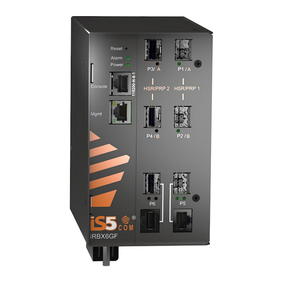
GETTING STARTED 1.1 About iRBX6GF The iRBX6GF (“the Switch”) is an Intelligent 6 Port Ethernet switch compliant with IEC 61850 and IEEE 1613 applications, with DIN rail and panel mount options, and optimized for harsh environments. The Switch provides redundant port for critical and high-availability networks. It supports both high- availability seamless redundancy (HSR, IEC 62439-3 Clause 5 [3]) and parallel redundancy protocol (PRP, IEC 62439-3 Clause 4 [3]). -
Page 10: References
User’s Manual 1.2 References [1] 802.1Q Virtual LANs (dot1q, VLAN tag) [2] RFC 1901, Introduction to Community-Based SNMPv2 [3] IEC 62439-3 Industrial communication networks - High availability automation networks - Part 3: Parallel Redundancy Protocol (PRP) and High-availability Seamless Redundancy (HSR) -
Page 11: Acronyms
User’s Manual 1.3 Acronyms The following table shows all acronyms used in this document. Acronym Explanation Command Line Interface Domain Name Server High-availability Seamless Redundancy Internet Protocol (IP) LLDP Link Layer Discovery Protocol LLDP- MED LLDP - Media Endpoint Discovery... -
Page 12: Software Features
User’s Manual 1.4 Software Features IEEE 802.1Q for VLAN Tagging compliant IEEE 802.1w for RSTP (Rapid Spanning Tree Protocol) IEEE 1588v2 PTP clock synchronization HSR (High-availability Seamless Redundancy) PRP (Parallel Redundancy Protocol) NTP Time Synchronization Precision Time Protocol (PTP) -
Page 13: Hardware Installation
User’s Manual HARDWARE INSTALLATION 2.1 DIN-Rail Installation Each switch has a DIN-Rail bracket on the rear panel. The DIN-Rail bracket helps secure the switch on to the DIN-Rail. 2.2 Mounting on DIN-Rail Step 1: Tilt the switch and position the top 2 catches of the metal bracket onto the top of the DIN-Rail. -
Page 14: Panel Mount Installation
User’s Manual 2.3 Panel Mount Installation The switch can also be panel or wall mounted. The following steps show how to mount the switch on a wall or panel. Mounting on Wall or Panel Option 1: Fix mounting brackets to the side of switch using the 4 screws included in the package. -
Page 15: Hardware Overview
User’s Manual HARDWARE OVERVIEW 3.1 Front Panel The following table describes the labels that are used on the iRBX6GF series. Table 1 – iRBX6GF Front Panel Port Description SFP ports 4 x 100 /1000Base-X SFP ports Combo Ports 2 x 10/100/1000Base-T(X) or 2 x 100 /1000Base-X SFP ports... -
Page 16: Front Panel Led
User’s Manual 3.2 Front Panel LED Table 2 – Front Panel LEDs Color Status Description Power Green DC power module up Alarm Alarm triggered 10/100/1000Base-T(X) Fast Ethernet ports Green Port link up Green Blinking Data transmitted Full Duplex Amber... -
Page 17: Bottom View Panel
The terminal block comes with a safety cover that must be removed before connecting any wires. The cover must be reattached after wiring for ensuring safety of personnel. The iRBX6GF series support dual redundant power supplies (PWR1 and PWR2). There are 3 options: •... - Page 18 Fault Relay Chassis Ground Connection The iRBX6GF’s chassis ground connection, which is located next to the terminal block, uses a #6-32 screw. We recommend terminating the ground connection using a #6 ring lug and a torque setting of 15 in.lbs (1.7Nm).
-
Page 19: Rear Panel
User’s Manual 3.5 Rear Panel The components on the rear of the iRBX6GF are as shown below: 1. 4 Holes for the screws for the wall mount kit 2. DIN-Rail mount 3.6 Side Panel The components on the side of the iRBX6GF are shown below: 1. -
Page 20: Cables
CABLES 4.1 Ethernet Cables The iRBX6GF switch has standard Ethernet ports. According to the link type, the switches use CAT 3, 4, 5, and 5e UTP cables to connect to any other network device (e.g. PCs, servers, switches, routers, or hubs). -
Page 21: Sfp
User’s Manual Table 8 – 10/100 Base-T(X) MDI/MDI- X Pin Assignments Pin Number M DI port M DI-X port TD+(transmit) RD+(receive) TD-(transmit) RD-(receive) RD+(receive) TD+(transmit) Not used Not used Not used Not used RD-(receive) TD-(transmit) Not used Not used... -
Page 22: Supported Sfps
User’s Manual 4.1.1 Supported SFPs iS5 Communications strongly recommends that suitable SFP modules are used. The SFP modules can be ordered from iS5 Communications according to the following table: Table 10 – iRBX SFP compatibility table P5,6 P1,2 P3,4... -
Page 23: Console Cable
4.3 Console Cable The iRBX6GF can be managed via the console port (a RS-232 Serial interface) by a RS-232 cable supplied with the switch. Connect the port to a PC using the RS-232 cable with an RJ-45 connector to a DB-9 female connector. -
Page 24: Syslog Guidelines
User’s Manual SYSLOG GUIDELINES 5.1 Managing Disk Space Syslog stores logging events. Depending on the compression level, from 16MB to 300MB of events may be stored. Periodically( every 1 hour), the system checks the space available and performs the following steps: 1. -
Page 25: Alarms Management
An alarm is a response to one or more related events. Only certain events generate alarms. Alarms have a state (cleared or not cleared) and a severity (for iRBX6GF, info, warn, error, critical). An alarm inherits the severity of its most recent event. Alarms remain open until a clearing event is generated (or if the alarm is manually cleared). -
Page 26: Alarms And Snmp Traps Configuration By Cli
6.4 Alarm Configuration by WEB UI iRBX6GF introduces a global alarm icon in the top right corner of the Web page which represents the status of the alarm. Color is changed to red if one or more alarms have been triggered. -
Page 27: Cold / Warm System Start
Stopping rsyslog daemon: OK Starting rsyslog daemon: OK System warm start after uptime 00:09:40 Welcome to iRBX Switch Copyright (c) 2017 iS5 Communications All rights reserved irbx login: 6.7 Fail Safe Relay Test using the following commands (login as root) cli.system.fsafe.on.sh... -
Page 28: Redundancy Overview
User’s Manual REDUNDANCY OVERVIEW 7.1 Introduction Industrial networks demand high availability and uninterrupted operation. A short loss of connectivity may have dramatic consequences in automation, power generation and distribution systems. Redundancy is used to minimize system downtime which is one of the most important concerns for industrial networking devices. -
Page 29: Prp
User’s Manual 7.2 PRP PRP (Parallel Redundancy Protocol) is a protocol standardized by IEC 62439-3 Clause 4 [3]. For more information, refer to: http://en.wikipedia.org/wiki/Parallel_Redundancy_Protocol Each node is connected to two separated and parallel networks (see the figure below). The nodes send two copies of each frame, one over each network. -
Page 30: Firmware Upgrade
User’s Manual FIRMWARE UPGRADE The iRBX6GF firmware can be upgraded via uBoot and WebUI. For firmware upgrade via WebUI, refer to Section 10.1.4.1 Firmware Upgrade. All upgrades are done through TFTP protocol as follows: 8.1 Connecting Connect management PC with iRBX6GF’s Management network port. -
Page 31: Configuring Tftp Server
User’s Manual 8.3 Configuring TFTP Server Use settings as shown in Figure 2 and Figure 3. Figure 2 – TFTP Server Configuration Figure 3 – TFTP Server Configuration (cont.) UM-iRBX6GF-4.5.1-EN.docx Pages 24 of 119... -
Page 32: Preparing Firmware Files
User’s Manual 8.4 Preparing Firmware Files Obtain iRBX firmware files and copy them to the TFTP server base directory (c:\tftp) • irbx-D-image-4.5.118.itb– firmware image for upgrade via Boot loader • irbx-uboot-5.34.itb (latest uboot version at the moment of writing this manual) 8.5 iRBX Boot Loader Menu... -
Page 33: Upgrade Procedure
User’s Manual 8.6 Upgrade Procedure Upgrading via Boot Loader Copy irbx_image-xxxxx.itb—firmware upgrade image file on TFTP Server to Base Directory (c:\TFTP). Setting up IP addresses • Set IP on PC and iRBX; make sure that IP addresses are in same subnet and pinging is successful. -
Page 34: Figure 5 - Irbx Boot Menu With Circles For Version No And File Name
User’s Manual Figure 5 – iRBX Boot Menu with Circles for Version No and File Name 4. Once TFTP server IP is set up, press Option 8 to download the itb file Figure 6 - Downloading the Current itb File 5. -
Page 35: Showing Fpga And Firmware Versions
@(config-snmp)# ! @(config-snmp)# system @(config-system)# banner "Welcome to iRBX Switch\\n Copyright (c) 2017 iS5 Communications\\n All rights reserved\\n" Welcome to iRBX Switch Copyright (c) 2017 iS5 Communications All rights reserved (config-system)# location Earth @(config-system)# name irbx @(config-system)# timezone America/Toronto @(config-system)# ! -
Page 36: Device Management
The iRBX6GF switch supports MIB which defines the Network Management interfaces for the redundancy protocols defined by the IEC 62439 suite including Simple Network Management Protocol (SNMP). SNMP v1 is supported. Standard SNMP browser can be used to manage iRBX6GF by using standard IEC-62439-3_Ed2 mib file. -
Page 37: Figure 7 - Tera Term Vt, Setup Menu
Use the following credentials to login (as illustrated on the figure below): iRBX login: admin Password: admin Welcome to iS5 Communications Copyright (c) 2017 iS5 Communications All rights reserved iRBX login: Figure 9 – Tera Term VT, Login Screen UM-iRBX6GF-4.5.1-EN.docx... -
Page 38: Command Line Interface Overview
User’s Manual 9.4 Command Line Interface Overview There are 3 configuration contexts: General Context, Show Context, and Configuration Context. To access Help in each configuration context, type a “?”. When you type a question mark (“ ?”), the following will appear in the 3 different contexts. - Page 39 Context Sensitive Help iRBX6GF CLI framework offers context sensitive help; The user can type a question mark (?) anytime during a session to get help. The help can be invoked in several ways. It is not displayed as a whole and is available only for the specific token from where it is invoked.
-
Page 40: General Command Line Interface Syntax
Send messages to network hosts show Show system information exit command iRBX# exit Welcome to iRBX Switch Copyright (c) 2017 iS5 Communications All rights reserved iRBX (config-alarm)# exit iRBX (config)# factory-reset command iRBX (config)# factory-reset please reboot the system iRBX (config)# Note: Command factory-reset requires reboot of the system to apply the configuration settings. - Page 41 User’s Manual ip command iRBX (config)# ip iRBX(config-ip)# lldp command iRBX (config)# lldp iRBX(config- lldp)# no command iRBX (config)# no ? Negate a command or set its defaults iRBX(config)# no ntp command iRBX (config)# ntp iRBX(config-ntp)# password command RBX(config)# password change...
- Page 42 8. Pull TFTP Firmware..[Image 0] 9. Edit TFTP Filename..[irbx-D-image-4.3.120.itb] 10. Edit MAC Address...[e8:e8:75:80:01:88] 11. Edit Unit Serial..[RBX64917-00006] 12. Edit Unit Model..[iRBX6GF-HV-HV-D-2GSFP-2GSFP-2GCX] 13. Save Boot Menu settings 14. Restore Boot Menu defaults U-Boot console Press UP/DOWN to move, ENTER to select ## Booting kernel from Legacy Image at d2000000 ...
- Page 43 User’s Manual ********************************************************************* CONFIGURATION FACTORY RESET ********************************************************************* Initializing random number generator... [ 17.879000] random: dd urandom read with 1 bits of entropy available done. Starting lighttpd: OK Starting lldpd: OK Starting ports PORT1..PORT6 24.490000] altera_tse 8044000.ethernet eth0: device MAC address e8:e8:75:80:01:88 24.500000] altera_tse 8044000.ethernet eth0: TSE revision 1001...
- Page 44 @(config-snmp)# ! @(config-snmp)# system @(config-system)# banner "Welcome to iRBX Switch\\n Copyright (c) 2017 iS5 Communications\\n All rights reserved\\n" Welcome to iRBX Switch Copyright (c) 2017 iS5 Communications All rights reserved @(config-system)# location Earth @(config-system)# name irbx @(config-system)# ! @(config-system)# vlan 1...
- Page 45 Syntax error on line /etc/startup-config:48 "session-timeout 30": Unknown command @(config-web-acl)# @(config-web-acl)# ip @(config-ip)# address 192.168.10.1/24 @(config-ip)# management-vlan 4 @(config-ip)# gateway 192.168.10.254 Welcome to iS5 Communications Copyright (c) 2017 iS5 Communications All rights reserved irbx login: redundancy command iRBX (config)# redundancy iRBX(config-redundancy)# rstp command...
-
Page 46: Command Exit
(config)# web iRBX(config-web)# Command exit iRBX# exit Welcome to iS5 Communications Copyright (c) 2018 iS5 Communications All rights reserved iRBX login: Command ping iRBX# ping 198.168.10.11 PING 198.168.10.11 (198.168.10.11): 56 data bytes --- 198.168.10.11 ping statistics ---... -
Page 47: Show Context Cli Syntax
Show firmware version show version command Show VLAN configuration and 22 show vlans show vlans command membership show banner command iRBX# show banner Welcome to iRBX Switch Copyright (c) 2018 iS5 Communications All rights reserved iRBX# UM-iRBX6GF-4.5.1-EN.docx Pages 40 of 119... -
Page 48: Show Config Command
1 enable snmp community 1 public read-only enable enable syslog enable system banner "Welcome to iRBX Switch\\n Copyright (c) 2017 iS5 Communications\\n All rights reserved\\n" location Earth name irbx vlan 1 ports 1,2,3,4,5,6 enable session-timeout 30 iRBX # UM-iRBX6GF-4.5.1-EN.docx... -
Page 49: Show Date Command
User’s Manual show date command iRBX# show date Mon Feb 25 05:28:51 UTC 2019 iRBX# show ip command iRBX# show ip Management interface: MGMT Link encap:Ethernet HWaddr E8:E8:75:00:03:12 inet addr:192.168.10.13 Bcast:192.168.10.255 Mask:255.255.255.0 UP BROADCAST RUNNING MULTICAST MTU:1500 Metric:1 RX packets:26637 errors:0 dropped:0 overruns:0 frame:0... -
Page 50: Show Lldp Command
Receive mode: no Pattern for management addresses: 192.168.10.13 Interface pattern: eth0,PORT1,PORT2,PORT3,PORT4,PORT5,PORT6 Interface pattern for chassis ID: (none) Override description with: iRBX6GF HSR/PRP Ethernet Switch Override platform with: Linux Override system name with: (none) Advertise version: no Update interface descriptions: no... -
Page 51: Show Ntp Command
User’s Manual show ntp command iRBX# show ntp ntp is enabled iRBX# show ports command iRBX# show ports Port Panel Enable Link Duplex RSTP --------------------------------------------------------- PORT1 P1/A down 1000x PORT2 P2/B down 1000x PORT3 P4/A down PORT4 P5/B down... -
Page 52: Show Rstp Command
User’s Manual show rstp command iRBX# show rstp Enabled Domain ID Self Bridge e8:e8:75:00:03:13 Root Bridge 0.000.e8:e8:75:00:08:5a Root Port PORT5 | Path Cost 20000 Max Age | Hello Time Forward Delay | Max Hops Tx Hold Count | Bridge Priority... -
Page 53: Show Stats Command
User’s Manual show stats command iRBX# how stats PORT1 PORT2 PORT3 PORT4 PORT5 PORT6 [ 0 x 3 1 0 2 ] rx_bad_octets [ 0 x 3 1 0 4 ] rx_unicast_packets 1 0 3 4 [ 0 x 3 1 0 6 ] rx_broadcast_packets... -
Page 54: Show Syslog
[ lldp rstp ssh system web ] 2019-02-25 06:35:26 irbx info lldp: PORT1 discovered iRBX6GF HSR/PRP Ethernet Switch 2019-02-26 00:06:38 irbx info lldp: PORT1 discovered iRBX6GF HSR/PRP Ethernet Switch 2019-02-26 01:21:39 irbx info lldp: PORT2 discovered iRBX6GF HSR/PRP Ethernet Switch... - Page 55 User’s Manual show syslog alarm iRBX# show syslog alarm info,warn,error,critical - filter by severity <cr> iRBX# show syslog alarm 9.6.15.1.1 show syslog alarm info, warn, error, critical iRBX# show syslog alarm info <cr> iRBX# show syslog alarm info iRBX# show syslog alarm warn <cr>...
-
Page 56: Table 18 - Show Syslog Facilities
INFO, NOTICE and WARN (<=3) For more information such as Values and Syslog Definition for other alarms’ severity level (e.g. debug) which are not available for iRBX6GF, refer to the table below. Table 20 – Alarms Severity Mapping Table Value Severity... - Page 57 - filter by severity <cr> iRBX# show syslog lldp 2019-02-25 06:35:26 irbx info lldp: PORT1 discovered iRBX6GF HSR/PRP Ethernet Switch 2019-02-26 00:06:38 irbx info lldp: PORT1 discovered iRBX6GF HSR/PRP Ethernet Switch 2019-02-26 01:21:39 irbx info lldp: PORT2 discovered iRBX6GF HSR/PRP Ethernet Switch...
- Page 58 User’s Manual 9.6.15.3.4 show syslog lldp critical iRBX# show syslog lldp critical <cr> iRBX# show syslog lldp critical iRBX# show syslog login iRBX# show syslog login info,warn,error,critical - filter by severity <cr> iRBX# show syslog login info No events...
- Page 59 User’s Manual show syslog search iRBX(config)# facility alarm,lldp,login,rstp,ssh,system,web - facility name iRBX(config)# exit iRBX# show syslog search? search through all facilities iRBX# show syslog search remote [ system ] 2019-03-01 00:31:01 10 info cdb: admin changed syslog_remote_2 iRBX# show syslog search info...
-
Page 60: Show System Command
User’s Manual show syslog web iRBX# show syslog web warn 2019-02-25 06:16:05 irbx err nginx: 2019/02/25 06:16:05 [error] 952#952: *1126 user "logout" was not found in "/etc/nginx/.password", client: 192.168.10.10, server: localhost, request: "PUT /s/index.html HTTP/1.1", host: "192.168.10.13", referrer: "http://192.168.10.13/index.html"... -
Page 61: Show Timezone Command
User’s Manual show timezone command iRBX# show timezone Etc/GMT-4 iRBX# Note: for Time Zone Map, refer to https://www.timeanddate.com/time/map/ . Toronto is -4. show timezone list command iRBX# show timezone list Africa/Abidjan Africa/Accra Africa/Addis_Ababa Africa/Algiers Africa/Asmara Africa/Asmera Africa/Bamako Africa/Bangui Africa/Banjul... - Page 62 User’s Manual Africa/Sao_Tome Africa/Timbuktu Africa/Tripoli Africa/Tunis Africa/Windhoek America/Adak America/Anchorage America/Anguilla America/Antigua America/Araguaina America/Argentina/Buenos_Aires America/Argentina/Catamarca America/Argentina/ComodRivadavia America/Argentina/Cordoba America/Argentina/Jujuy America/Argentina/La_Rioja America/Argentina/Mendoza America/Argentina/Rio_Gallegos America/Argentina/Salta America/Argentina/San_Juan America/Argentina/San_Luis America/Argentina/Tucuman America/Argentina/Ushuaia America/Aruba America/Asuncion America/Atikokan America/Atka America/Bahia America/Bahia_Banderas America/Barbados America/Belem America/Belize America/Blanc-Sablon America/Boa_Vista America/Bogota America/Boise America/Buenos_Aires...
- Page 63 User’s Manual America/El_Salvador America/Ensenada America/Fort_Nelson America/Fort_Wayne America/Fortaleza America/Glace_Bay America/Godthab America/Goose_Bay America/Grand_Turk America/Grenada America/Guadeloupe America/Guatemala America/Guayaquil America/Guyana America/Halifax America/Havana America/Hermosillo America/Indiana/Indianapolis America/Indiana/Knox America/Indiana/Marengo America/Indiana/Petersburg America/Indiana/Tell_City America/Indiana/Vevay America/Indiana/Vincennes America/Indiana/Winamac America/Indianapolis America/Inuvik America/Iqaluit America/Jamaica America/Jujuy America/Juneau America/Kentucky/Louisville America/Kentucky/Monticello America/Knox_IN America/Kralendijk America/La_Paz America/Lima...
- Page 64 User’s Manual America/Nipigon America/Nome America/Noronha America/North_Dakota/Beulah America/North_Dakota/Center America/North_Dakota/New_Salem America/Ojinaga America/Panama America/Pangnirtung America/Paramaribo America/Phoenix America/Port-au-Prince America/Port_of_Spain America/Porto_Acre America/Porto_Velho America/Puerto_Rico America/Rainy_River America/Rankin_Inlet America/Recife America/Regina America/Resolute America/Rio_Branco America/Rosario America/Santa_Isabel America/Santarem America/Santiago America/Santo_Domingo America/Sao_Paulo America/Scoresbysund America/Shiprock America/Sitka America/St_Barthelemy America/St_Johns America/St_Kitts America/St_Lucia America/St_Thomas America/St_Vincent...
- Page 65 User’s Manual Antarctica/Troll Antarctica/Vostok Arctic/Longyearbyen Asia/Aden Asia/Almaty Asia/Amman Asia/Anadyr Asia/Aqtau Asia/Aqtobe Asia/Ashgabat Asia/Ashkhabad Asia/Baghdad Asia/Bahrain Asia/Baku Asia/Bangkok Asia/Barnaul Asia/Beirut Asia/Bishkek Asia/Brunei Asia/Calcutta Asia/Chita Asia/Choibalsan Asia/Chongqing Asia/Chungking Asia/Colombo Asia/Dacca Asia/Damascus Asia/Dhaka Asia/Dili Asia/Dubai Asia/Dushanbe Asia/Gaza Asia/Harbin Asia/Hebron Asia/Ho_Chi_Minh Asia/Hong_Kong Asia/Hovd...
-
Page 66: Show Uptime Command
User’s Manual Asia/Nicosia Asia/Novokuznetsk Asia/Novosibirsk Asia/Omsk Asia/Oral Asia/Phnom_Penh Asia/Pontianak Asia/Pyongyang Asia/Qatar Asia/Qyzylorda Asia/Rangoon Asia/Riyadh Asia/Saigon Asia/Sakhalin Asia/Samarkand Asia/Seoul Asia/Shanghai Asia/Singapore Asia/Srednekolymsk iRBX# show uptime command iRBX# show uptime 5d,17:57:51 iRBX# show version command iRBX# show version show version Version=4.5.114... -
Page 67: Configuration Context Cli Syntax
User’s Manual 9.7 Configuration Context CLI Syntax In the Configuration Context, the user can configure switch system parameters, ports, PTP, VLANs, RSTP, SNMP, etc. To go to the Configuration Context, execute configure terminal command first. When the (config)# prompt appears, use the commands shown in the following table. -
Page 68: Alarm Command
User’s Manual alarm command iRBX(config)# alarm iRBX(config-alarm)# Comments exit from alarm configuration mode monitor-ports Alarm if ports change link state monitor-power Alarm if power supply is off monitor-temperature Alarm if temperature is higher than threshold snmp-trap-community SNMP trap community name... -
Page 69: Do Command
Welcome to iS5 Communications Copyright (c) 2017 iS5 Communications All rights reserved iRBX(config-system)# do show log-auth Apr 17 17:05:41 irbx sshd[1791]: Server listening on 0.0.0.0 port 22. Apr 17 21:40:58 irbx sshd[1791]: Received signal 15; terminating. -
Page 70: Factory-Reset Command
User’s Manual factory-reset command iRBX(config)# factory-reset please reboot the system iRBX(config) reboot 205.376000] br0: port 5(PORT6) entered disabled state 205.377000] PORT6: bridge state 0 ********************************************************************* CONFIGURATION FACTORY RESET ********************************************************************* Initializing random number generator... [ 17.852000] random: dd urandom read with 3 bits of entropy available done. -
Page 71: Lldp Command
User’s Manual exit command iRBX(config-ip)# exit iRBX(config)# gateway command iRBX(config-ip)# gateway ? A.B.C.D IP address of default gateway iRBX(config-ip)# gateway 192.168.10.254 iRBX(config-ip)# management-vlan command iRBX(config-ip)# management-vlan ? vlan number in the range 1-4095 0-4095 iRBX(config-ip)# iRBX(config-ip)# management-vlan 4 iRBX(config-ip)#... -
Page 72: No Command
User’s Manual To see all LLDP configuration, Global statistics, and neighbors, use the do show lldp command. no command iRBX(config)# no Negate a command or set its defaults RBX(config)# no interlink Unset port as interlink vlan Delete vlan iRBX(config)#... -
Page 73: Password Command
User’s Manual exit command iRBX(config-ntp)# exit iRBX(config) server1 command iRBX(config-ntp)# server server1 server2 iRBX(config-ntp)# server server1 Add time server 1 server2 Add time server 2 iRBX(config-ntp)# server1 1.pool.ntp.org Note: type server1 without a space. server2 command iRBX(config-ntp)# server2 2.pool.ntp.org... - Page 74 User’s Manual enable command iRBX(config-port2)# enable PORT2: power is up iRBX(config-port2)# exit command iRBX(config)# port 6 iRBX(config-port6)# exit iRBX(config)# exit iRBX# pvid command iRBX(config-port2) vlan number in the range 1-4095 iRBX(config-port2)# pvid pvid Set port default vlan iRBX(config-port2) tapvid 10...
-
Page 75: Ptp Command
User’s Manual ptp command iRBX(config-ptp)# Comments disable Disable ptp enable Enable ptp exit Exit from ptp configuration mode mode enable or disable tagging of PTP traffic one-step Enable one-step ptp clock mode Priority code (PCP) sync Enable host clock sync to PTP time... -
Page 76: Reboot Command
User’s Manual sync command iRBX(config-ptp)# sync sync Enable host clock sync to PTP time <cr> iRBX(config-ptp)# sync iRBX(config-ptp)# vlan command iRBX(config-ptp)# vlan ? vlan VLAN ID for PTP messages iRBX(config-ptp)# vlan 1 setting PTP VLAN 1 PCP 5 irbx(config-ptp)#... -
Page 77: Rstp Command
User’s Manual netid command iRBX(config)# redundancy iRBX(config-redundancy)# netid netid Set PRP NetID iRBX (config-redundancy)# netid 1..6 PRP NetID iRBX(config-redundancy)# netid 6 [0x8] <- 0x0202 Redundancy: using HSR mode with I-Port on PORT5 iRBX(config-redundancy)# Note that the netid’s value is from 1 to 6. If HSR-PRP-A and HSR-PRP-B is chosen, the netID is defined 1 by default. - Page 78 User’s Manual disable command iRBX(config-rstp)# disable PORT5: bridge state 0 PORT5: bridge state disabled (122) PORT1: bridge state 0 PORT1: bridge state disabled (122) PORT1: bridge tunnel mode PORT2: bridge state 0 PORT2: bridge state disabled (122) PORT2: bridge tunnel mode...
- Page 79 User’s Manual domain command iRBX(config-rstp)# domain Number 0..9 in range (0-9), default is 0 (no separation) iRBX(config-rstp)#domain 1 iRBX(config-rstp)# exit command iRBX(config-rstp)# exit iRBX(config)# fdelay command iRBX(config-rstp)# fdelay ? Number in range (4-30), default is 15 iRBX(config-rstp)# fdelay 5 CTL_set_cist_bridge_config: Got return code 0, -1 br0 Configured Bridge Times don't meet 2 * (Bridge Forward Delay - 1 second) >=...
- Page 80 User’s Manual port command iRBX(config-rstp)# port R(redundancy),3,4,5,6 port number iRBX(config-rstp)# port R,3 iRBX(config-rstp-port-R,3)# Comments admin-edge Enables/disables the initial edge state of the port, default is no auto-edge Enables/disables the auto transition to/from the edge state, default is yes bpdu-discard...
- Page 81 User’s Manual 9.7.14.9.6 iRBX(config-rstp-port-R,3)# p2p Choice: auto|yes|no iRBX(config-rstp-port-R,3)# p2p auto iRBX(config-rstp-port-R,3)# 9.7.14.9.7 path-cost iRBX(config-rstp-port-R,3)# path-cost Number 0..200000000, default is 0 iRBX(config-rstp-port-R,3)# path-cost 100 iRBX(config-rstp-port-R,3)# 9.7.14.9.8 port-priority iRBX(config-rstp-port-R,3)# port-priority Port priority a multiple of 16 in range (0-240), default is 128...
-
Page 82: Save Command
User’s Manual To view the changes in the RSTP parameters, use the do show rstp command. iRBX(config-rstp)# do show rstp Enabled Domain ID Self Bridge e8:e8:75:80:01:89 Root Bridge 8.000.e8:e8:75:80:01:89 Root Port none | Path Cost Max Age | Hello Time... -
Page 83: Ssh Command
User’s Manual disable command iRBX(config-snmp)# disable Stopping network management services: snmpd snmptrapd. iRBX(config-snmp)# enable command iRBX(config)# snmp iRBX(config-snmp)# enable Restarting network management services: snmpd. iRBX(config-snmp)# exit command iRBX(config-snmp)# exit iRBX(config-snmp)# v3-user command iRBX(config-snmp)# v3-user 1..4 entry number iRBX(config-snmp)# v3-user 1... - Page 84 User’s Manual enable command iRBX(config)# ssh iRBX(config-ssh)# enable Starting sshd: OK iRBX(config-ssh)# exit command iRBX(config)# ssh iRBX(config-ssh)# exit iRBX(config)# keygen command iRBX(config-ssh)# keygen It might take around 20min. Continue? [y/N]y Wed Apr 18 11:11:55 UTC 2018 Generating public/private rsa key pair.
- Page 85 User’s Manual Wed Apr 18 11:19:29 UTC 2018 Wed Apr 18 11:19:29 UTC 2018 Generating public/private ecdsa key pair. Your identification has been saved in /data/etc/ssh_host_ecdsa_key. Your public key has been saved in /data/etc/ssh_host_ecdsa_key.pub. The key fingerprint is: d1:2b:5b:2c:97:bb:95:a8:e8:48:d5:79:b3:b1:46:62 root@iRBX...
-
Page 86: Syslog Command
User’s Manual syslog command iRBX(config)# syslog iRBX (config-syslog)# Comments clear Clear all facilities defaults Reset syslog configuration to defaults disable Disable syslog service enable Enable syslog service exit Exit from syslog configuration mode facility Configure facility remote Configure remote forwarding rule... - Page 87 2019-02-25 06:35:09 irbx info kernel:PORT1: link is up 2019-02-25 06:35:09 irbx notice alarm: PORT1 is up 2019-02-25 06:35:26 irbx info lldp: PORT1 discovered iRBX6GF HSR/PRP Ethernet Switch 2019-02-25 06:36:36 irbx info kernel:PORT1: link is down 2019-02-25 06:36:37 irbx notice alarm: PORT1 is down...
-
Page 88: System
User’s Manual 9.7.18.6.4 clear iRBX (config-syslog-alarm)# clear clear Clear facility messages <cr> iRBX (config-syslog-alarm)# clear iRBX (config-syslog-alarm)# 9.7.18.6.5 exit iRBX (config-syslog-alarm)# exit exit Exit from facility configuration mode <cr> iRBX (config-syslog-alarm)# exit iRBX (config-syslog-alarm)# remote command iRBX (config-syslog)# remote 1..64... - Page 89 String Enter a text surrounded by double quotes. Use \\n as newline iRBX(config-system)# banner "this is iS5Com's new switch" this is iS5Com's new switch iRBX(config-system)# banner "Welcome to iS5 Communications" Welcome to iS5 Communications iRBX (config-system)# date iRBX(config)# (config-system)# date...
-
Page 90: Vlan Command
User’s Manual A do show system command can be executed to see all show parameters. iRBX (config-system)# do show system Name : irbx Model Serial HW Revision Location : Earth MAC Address : E8:E8:75:00:03:12 (management) MAC Address : E8:E8:75:00:03:13 (internal) -
Page 91: Web Command
User’s Manual Use the do show vlans command to see all vlans’ settings. iRBX(config-vlan3)# do show vlans Vlan Ports ------------------------------------- 1,2 (0x7) 3,4 (0x19) 5,6 (0x61) Management VLAN ------------------------------------- Port Panel PVID Egress ------------------------------------- PORT1 P1/A untagged PORT2 P2/B... - Page 92 User’s Manual 9.7.21.1.2 Command exit iRBX(config-web-acl)# exit iRBX(config-web)# 9.7.21.1.3 Command rule iRBX(config-web-acl)# rule 1..4 iRBX(config-web-acl)# rule 1 allow 4 iRBX(config-web-acl)# Command disable iRBX(config-web)# disable Stopping lighttpd: OK iRBX(config-web)# Command enable iRBX(config-web)# enable Stopping lighttpd: OK Starting lighttpd: OK iRBX(config-web)#...
- Page 93 User’s Manual 9.7.21.6.1 Cert-delete iRBX (config-web-ssl))# cert-delete iRBX (config-web-ssl)# 9.7.21.6.2 Cert-export iRBX (config-web-ssl)# cert-export No certificate found iRBX (config-web-ssl)# 9.7.21.6.3 Cert-generate iRBX (config-web-ssl)cert-generate Generate self-signed RSA Certificate. Continue? [y/N] Generate self-signed RSA Certificate. Continue? [y/N]y Generating a 1024 bit RSA private key ..++++++...
-
Page 94: Web Management
An embedded HTML web site resides in the flash memory of the CPU board. It contains advanced management features that allow the user to manage the iRBX6GF switch from anywhere on the network via a standard web browser such as Microsoft Internet Explorer. -
Page 95: Figure 11 - Login Screen
User’s Manual 3. The Welcome to iRBX6GF screen appears. Click 4. The login screen appears (see Figure 11 – Login Screen). Figure 11 – Login Screen 5. Enter the username and password. The default username and password are “admin”. -
Page 96: System
User’s Manual 10.1 System System tab See above Figure 12 – Main Interface or System tab. The following table describes the labels for the System tab. Label Description Enter the current date. The format is yyyymmddhhii Uptime Power Shows if the power is ON Name Enter an alternate Name for the switch. -
Page 97: Maintenance
User’s Manual Figure 14 – IP Interface The following table describes the labels for the IP Interface screen. Label Description IP address Set management IP address / mask. The default is shown Gateway Set Gateway address. The default is shown. -
Page 98: Figure 16 - Firmware Upgrade Interface
User’s Manual Firmware Upgrade Figure 16 – Firmware upgrade Interface The following table describes the labels for the Firmware upgrade screen. Label Description Firmware upgrade Select irbx-D-image-X.Y.Z.tar Upload Upload the selected file. Configuration Figure 17 – Configuration Interface The following table describes the labels for the Configuration Interface screen. -
Page 99: Alarm
User’s Manual Alarm Figure 19 – Alarm Interface The following table describes the labels for the Alarm Interface screen. Label Description PORT1 To have an alarm warning if this port is down, add a checkmark in the Monitor box. -
Page 100: Figure 20 - Alarms To Generate Snmp Trap Interface
User’s Manual Label Description To have an alarm warning if the temperature is, change the default value of the Temperature threshold temperature. The default is 75 ºC. Status It shows the status. The options are down, up, on or off, or a value for temperature. -
Page 101: Banner
User’s Manual Banner Figure 22 – Banner Interface The following table describes the labels for the Banner Interface screen. Label Description Banner To change the default text in the Banner, enter new text in the box. Save Click to save changes. -
Page 102: Figure 24 - Control, Syslog Interface
User’s Manual Control Figure 24 – Control, Syslog Interface The following table describes the labels for the Control, Syslog Interface screen. Label Description Enable To monitor disk usage, add a checkmark in the box. Defaults If that is successful, the following Success! Syslog defaults set”... -
Page 103: Figure 26 - Search, Syslog Interface
User’s Manual Label Description Facility The name of the facility e.g. lldp Enable Enter a checkmark to enable a facility. By default, all facilities are enabled. Clear Click to clear it. Severity Select a severity. The options are info, warn, error, and critical. The default is info. -
Page 104: Figure 28 - Syslog Remote Rule Entry, Syslog Interface
User’s Manual Server Remote server IP address. Protocol The protocol to be used – UDP (User Datagram Protocol) Port Port No 514 is used for system logging, Syslog, [10] Click to delete a rule. Click to edit Syslog Remote Rule Entry. -
Page 105: Redundancy
User’s Manual 10.2 Redundancy Figure 29 – Redundancy Interface Redundancy Mode The two redundancy protocols specified by IEC 62439-3 [3] are: • PRP (Parallel Redundancy Protocol) • HSR (High-availability Seamless Redundancy) Figure 30 – Redundancy Mode Interface The following table describes the labels for the Redundancy Mode Interface screen. -
Page 106: Redundancy Ring Nodes (Irenodes Table)
Click to undo any changes made locally and revert to the saved ones. Note: iRBX6GF is using PRP mode with PORT5 as an I-Port (Interlink port) as seen in dimmed field next to I-PORT label. Port 5 is I-Port when HSR-PRP-A/B (Dual RedBox) mode is in use. For more details on Dual RedBox, see Section 7.3 HSR-PRP (Dual RedBox Mode). -
Page 107: Ports
User’s Manual 10.3 Ports This setting allows managing individual ports of the switch. Figure 32 – Ports Interface Ports Control Figure 33 – Ports Control Interface The following table describes the labels for Ports Control Interface screen. Label Description Enable Add a checkmark to enable it. -
Page 108: Ports Status
Figure 35 – Ports Statistics Interface This table shows read-only information about ports statistics. Ports statistics can be accessed by using show stats command. 10.4 Protocols This web page shows all protocols available for iRBX6GF: UM-iRBX6GF-4.5.1-EN.docx Pages 101 of 119... -
Page 109: Rstp
User’s Manual • RSTP (Rapid Spanning Tree Protocol) • PTP (Precision Time Protocol) • LLDP (Link Layer Discovery Protocol) • NTP (Network Time Protocol) • SNMP (Simple Network Management Protocol) Figure 36 – Protocols Interface RSTP RSTP Bridge Figure 37 – RSTP Bridge Interface The following table describes the labels for the RSTP Bridge screen. - Page 110 User’s Manual Label Description To enable the RSTP Bridge, check the box adjacent to the Enable label. By RSTP Bridge < default, the RSTP Bridge is not enabled. Note: In discussions of spanning-tree Enable protocols, the terms bridge and switch are often used interchangeably.
-
Page 111: Figure 38 - Rstp Ports Interface
User’s Manual RSTP Ports Figure 38 – RSTP Ports Interface The following table describes the labels for the RSTP Ports screen. Label Description Port # This is read-only column; R (A,B), 3, 4, 5, and 6. Link This is a read-only field with a value of up or down. - Page 112 User’s Manual Label Description This is a read-only column with a value of discarding for all ports, except for Port 6 for which the value is forwarding. Discarding means that no user data is sent to a port, State and forwarding state of a port–a fully operational port.
-
Page 113: Ptp
User’s Manual The purpose of Precision Time Protocol (PTP), as defined by IEEE 1588-2008 [4], is to synchronize independent clocks running on separate nodes of a distributed measurement and control system to a high degree of accuracy and precision. -
Page 114: Figure 41 - Ptp, Status Interface
User’s Manual The following table describes the labels for the PTP, Control Interface screen. Label Description To enable PTP, check the box adjacent to the Enable label. By default, PTP not Enable enabled. If checked, the One-step PTP clock mode is enabled. This is the default setting. -
Page 115: Lldp
User’s Manual LLDP HSR supports LLDP (Link Layer Discovery Protocol) which provides an efficient Layer2 neighbor discovery mechanism. It allows devices to advertise information about them to peer devices on the same LAN and to learn information about peer devices. -
Page 116: Figure 42 - Lldp Interface
User’s Manual Control and LLDP Neighbor Table Figure 42 – LLDP Interface The following table describes the labels for the LLDP Interface screen. Label Description Control To enable LLDP, check the box adjacent to the Enable label. By default, LLDP is enabled. -
Page 117: Ntp
User’s Manual Network Time Protocol (NTP) is a protocol used to synchronize computer clock times in a network. NTP uses Coordinated Universal Time (UTC) to synchronize computer clock times with extreme precision, offering greater accuracy on smaller networks -- down to a single millisecond in a local area network and within tens of milliseconds over the internet. -
Page 118: Snmp
User’s Manual SNMP Simple Network Management Protocol (SNMP), the most widely-used network management protocol on TCP/IP-based networks, is used for collecting information from /and configuring, network devices, such as servers, printers, hubs, switches, and routers on an Internet Protocol (IP) network. -
Page 119: Figure 46 - Snmp V3 Authorized Users Interface
User’s Manual The following table describes the labels for the SNMP v2 Interface screen. Label Description Control To enable SNMP, check the box adjacent to the Enable label. By default, SNMP is Enable enabled. SNMP v2 Authorized Communities A community string number. Default is 1 public read-only The default Community name is public and is read-only field for community # 1. - Page 120 User’s Manual The following table describes the labels for the SNMP v3 Authorized Users Interface screen. Label Description Number of Authorized users. This a read only column with 4 numbers:1,2,3, and 4. To create a new SNMP v3 Authorized User, click .
-
Page 121: Vlan
User’s Manual 10.5 VLAN Figure 47 – VLAN Interface Use the VLAN web page to configure port membership. The following table describes the labels for the VLAN Interface screen. Label Description VLAN Add a VLAN number. The default is 1. The example in shows 2. -
Page 122: Services
User’s Manual 10.6 Services Figure 49 – Services, Web tab Interface The following table describes the labels for the Services, Web tab Interface screen. Label Description Control Session Timeout Enter Session duration Apply Click Apply to save the changes. -
Page 123: Figure 50 - Access Control Rules, Web Tab Interface
User’s Manual Access Control Rules Figure 50 – Access Control Rules, Web tab Interface The following table describes the labels for the Services, Web tab Interface screen. Label Description Number of rule. Access The options are allow and deny. The default is allow Rule A pattern (e.g. -
Page 124: Ssh
User’s Manual SSH (Secure Shell) is a cryptographic network protocol for operating network services securely over an unsecured network. An example application is a remote login to computer systems by users. Figure 51 – Services, SSH tab Interface The following table describes the labels for the Services, SSH tab Interface screen. -
Page 125: Technical Specifications
User’s Manual TECHNICAL SPECIFICATIONS Model Number iRBX6GF Physical Ports 10/100/1000Base-T(X) RJ45 and 100/1000Base-X SFP 2 Combo Ethernet ports (Port 5 & 6) 100/1000Base-X SFP Ethernet ports 100/1000Base-X SFP 2 HSR/ PRP ports (Port 1 &2) PPS and IRIG-B Outputs (for future releases) - Page 126 User’s Manual Model Number iRBX6GF Regulatory Approvals IEC & IEEE IEC 61850-3, IEEE 1613, IEC 62439-3 FCC Part 15, Class A, CISPR Class A (EN55022) IEC 61000-4-2 (ESD), IEC 61000-4-3 (Radiated RFI), IEC 61000-4-4 (Burst), IEC 61000-4-5 (Surge), IEC 61000-4-6 (Induced (Conducted) RFI), IEC 61000-4-8, IEC 61000-4-11...
Need help?
Do you have a question about the iRBX6GF and is the answer not in the manual?
Questions and answers