
Related Manuals for ETC Sensor3 CEM3


Summary of Contents for ETC Sensor3 CEM3
- Page 1 Sensor3 CEM3 User Manual Version 1.7.0 Part Number: 7140M1200-1.7.0 Rev: C Released: 2019-04...
- Page 2 T o v ie w a l i s t o f E T C t r a d e m a r k s a n d p a t e n t s , g o t o etcconnect.com/ip A l l o t h e r t r a d e m a r k s , b o t h m a r k e d a n d no t m a r k e d , a r e t h e p r o p ert y o f t h ei r r es p e c ti v e o w ne r s .
-
Page 3: Table Of Contents
Text Conventions ........1 Help from ETC Technical Services ....2 Getting Started . - Page 4 Dimmer Curves .......21 Linear..........21 Modified Linear (Mod-Linear) .
- Page 5 Web Access and Mobile App ..42 Chapter 4 Using the CEM3 Web Interface ....42 System .
- Page 6 FDX 3000 Dimmer Racks ....63 Appendix D Hardware ........63 Front Panel .
-
Page 7: Introduction
Introduction Welcome to your new CEM3 Power Control system. This manual is designed to introduce you to the CEM3 user interface and the primary features and functions available to you in the setup and use of your CEM3 power control system. Using this Manual The following graphics and conventions are used throughout this manual to convey important information. -
Page 8: Help From Etc Technical Services
Dimming and Networking Systems page at community.etcconnect.com. If none of these resources are sufficient, contact ETC Technical Services directly at one of the offices identified below. Emergency service is available from all ETC offices outside of normal business hours. -
Page 9: Chapter 1 Getting Started
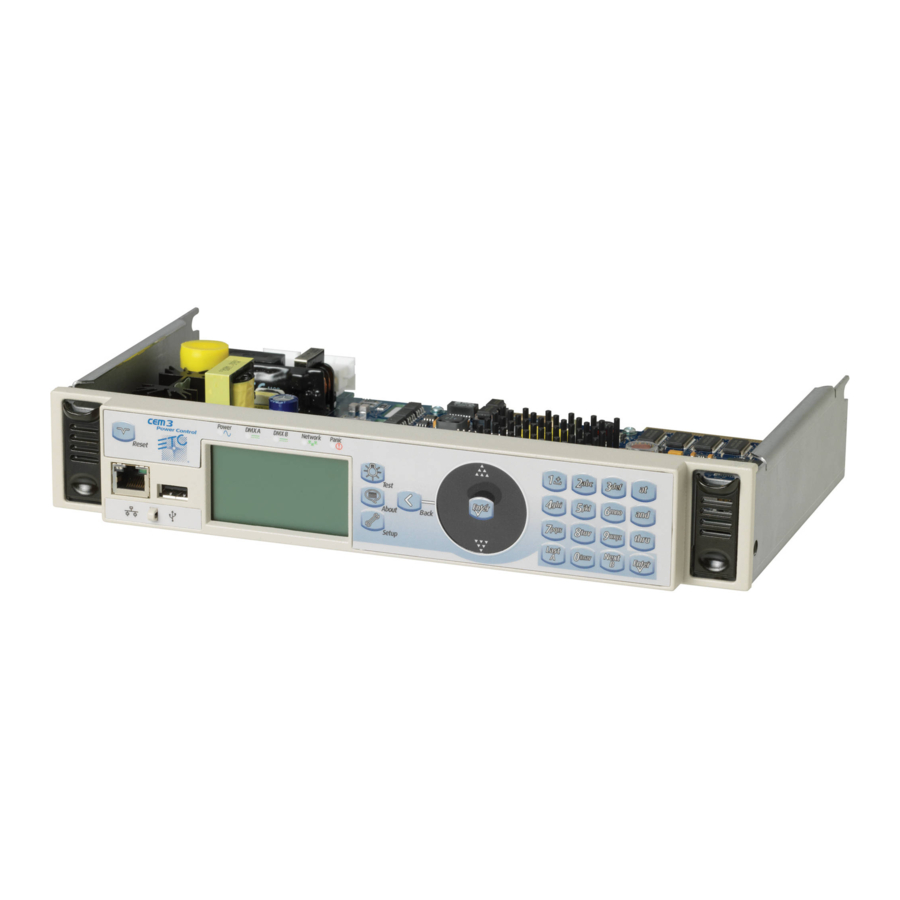
Chapter 1 Getting Started The User Interface This section explains the physical features of the hardware interface and their general functionality with the software. CEM3 Face Panel The diagram below shows the components of the hardware interface. These terms are used throughout this manual. -
Page 10: Performing A Quick Setup
Quick Setup will overwrite some of the data in your rack. Only perform a Quick Setup when you want to reconfigure your system or are instructed to do so by ETC Technical Services. You can begin a Quick Setup by selecting Quick Setup from the main screen or by navigating to [Setup]>Quick Setup>[Enter]. -
Page 11: Other Setup Functions
These tables compare the circuit numbering of an SR3-6 filled with D20 modules when set to Straight numbering, 3-Phase numbering, or 1-Phase numbering: SR3-6 SR3-6 SR3-6 Straight 3-Phase Phase 1-Phase Phase Circuit Numbering Circuit Numbering Circuit Numbering Dimmer Double (120V SR and SP Type Racks Only) Choose between Yes and No to activate or deactivate dimmer doubling for the rack. -
Page 12: Chapter 2 System Reference
The key to this feature is the Dimmer Doubler two-fer. The Dimmer Doubler two-fer is installed between a Sensor dimmer module and two ETC Source Four 77-volt fixtures. It splits the output of a single dimmer into two separately controlled outputs. -
Page 13: Latch-Lock
Latch-Lock Latch-Lock is a control mode available to any dimmer circuit (see Control page 17 ). Similar to switched mode, Latch-Lock features an additional safeguard so that circuits cannot be turned on or off defined specified as easily. The circuit only turns on when a control level range is held for a amount of time, and only turns off when a different control level range is held for another amount of time. -
Page 14: Panic
Panic CEM3 offers a panic capability that complies with the UL 924 standard. When a properly connected and enabled CEM3 has a panic “look” stored, it will automatically play the recorded look when it receives a signal over the panic circuit. Panic can be enabled when a maintained (normally open or normally closed) contact closure is properly wired to the backplane. -
Page 15: Preset Functions
Preset Functions CEM3 supports a built-in preset control system allowing the recording and playback of preset looks. Once recorded, preset looks can be played back either from the CEM3 face panel, connected Echo preset stations, or the web interface. For more information on recording and playing back presets see Recording and Playing Presets page 27 Circuit Assignment... -
Page 16: Redundant Tracking (Esr And Fdx Racks Only)
Rig Check Advanced Features (AF) page 6 In Sensor3 racks with Advanced Features (see ) you can record a special preset called Rig Check, which includes both circuit levels and the amount of load (current) expected on each circuit. Once recorded, the Rig Check can be played back, either from the CEM3 face panel or remotely, and load high load low no load... -
Page 17: Variable Speed Fan (Esr Series Racks Only)
Variable Speed Fan (ESR Series Racks Only) The variable speed fan reduces the amount of noise generated by a Sensor3 rack, specifically when the rack is lightly loaded. The variable speed fan (where available) is supported in the following product models: •... -
Page 18: Test
Test Field Description Set levels for outputs from this rack only. This will present a table-style view of the outputs in this rack and allow setting and releasing of levels. To set levels: • Select a circuit by numeric entry or scrolling with the wheel •... - Page 19 Example: Setting the A and B sides of one dimmer doubled circuit at a time is straightforward using the A and B keys. It is possible to set ranges of dimmer doubled circuits. The following are valid examples: A side only •...
-
Page 20: About
About Field Description View all properties for any circuit in a space or in any rack on the network. Dimmers Dimmer Property Definitions page 17 Rack Property Definitions View all properties for the host Sensor rack. See page 20 Rack •... -
Page 21: Setup
Setup Commonly used features found here include: • changing dimmer, rack, and network settings • enabling control ports • changing operating mode • upgrading software or backing up the rack configuration • changing curve and firing mode Field Description View and adjust the settings for any circuit in any rack connected to the Dimmers Dimmer Property Definitions page 17... -
Page 22: Ui Preferences
UI Preferences Adjust various settings regarding the user interface. Edit these settings in the UI Preferences Setup screen [Setup]>UI Preferences. Field Description Adjust the settings of the backlight behind the display window. Choices are Backlight Mode On, Off, and Auto. Auto will illuminate the window after a button press or boot up for the time specified in Backlight Time. -
Page 23: Dimmer Property Definitions
Dimmer Property Definitions Each dimmer has specific properties that dictate how the dimmer functions and how CEM3 will control it. Edit these properties in the Dimmer Setup screen [Setup]>Dimmers. Dimmer Setup Submenu Definition screen (if applicable) Circuit Number. A user-assigned number for a unique circuit within a space. - Page 24 Dimmer Setup Submenu Definition screen (if applicable) The current operating curve for the dimmer. Options are: Square, Mod-Square, Linear, Mod-Linear, and more. See Dimmer Curves Curve page 21 for a complete listing of curves and their descriptions. In switched mode the threshold value defines the control percentage at which the output turns on.
- Page 25 Dimmer Setup Submenu Definition screen (if applicable) Dimmer Output Set the minimum scale voltage of the circuit. See Min Scale (VAC) Diagram page 26 for an illustration relating to this property. Dimmer Set the maximum scale voltage of the circuit. See Max Scale (VAC) Output Diagram page 26...
-
Page 26: Rack Property Definitions
Rack Property Definitions Each rack has specific properties that dictate how the rack is identified and functions. Edit these properties in the Rack Setup screen ([Setup]>Rack). Rack Property Definition Rack Number Select a rack number between 1–999. Select a system number between 1–999. Default is 1. Changing the System Number system number will require a reboot. -
Page 27: Dimmer Curves
Dimmer Curves Dimmer curves determine voltage output in response to control signal input. To accommodate designer preferences and load response variations, Sensor3 offers several dimmer curves, which can be Curve page 18 applied to individual dimmers (see The available curves in CEM3 are as follows. Linear The linear curve matches the control input percentage to Root Mean Squared (RMS) voltage output. -
Page 28: Square Law (Square)
A standard square law curve may overcompensate for infrared loss, resulting in “steppy” response to incremental control changes at low levels. The ETC modified square law curve applies a second multiple to the standard square law curve for more uniform response to control levels changes across the entire range of dimmer output. -
Page 29: Sensor 2.0
Sensor 2.0 The Sensor 2.0 curve is the previous version of the ETC modified square law curve. It provides backwards compatibility for shows created using earlier versions of ETC equipment and familiar response for designers who prefer the earlier version. -
Page 30: Stage 2
Stage 2 This is a traditional German stage lighting curve. Control Input (%) Fluro1 This curve is specifically for Nesys fluorescent devices. Control Input (%) Fluro 2 This curve is tuned to work with common 3-wire fluorescent ballasts. Control Input (%) CEM3 User Manual... -
Page 31: Andi
VIP90 is a curve specifically tuned to produce good dimming performance with the VIP-90 fluorescent ballast from SE Light management AG, commonly used in European theatrical fluorescent luminaires. Control Input (%) Custom You can use ETC’s Concert software to configure up to five custom curves. System Reference... -
Page 32: Dimmer Output Diagram
Dimmer Output Diagram This diagram illustrates the relationship between min scale, max scale, curve, threshold, and preheat for the dimmer output from a CEM3 channel. Threshold(%) 100% Max Scale Voltage Min Scale Voltage Control Level With Preheat Disabled With Preheat Enabled Output is at min scale Output goes to zero below threshold... -
Page 33: Common Tasks
CEM3 has the ability to record and play back snapshot looks called “Presets.” Presets can be recalled from the CEM3 or from any compatible Echo preset stations or the web Sensor3 CEM3 Data Terminations Guide interface. For information on wiring preset stations, see the Echo preset Station Installation Guide. -
Page 34: Preset Menu
Preset Menu that Presets are recorded by taking a snapshot of the current levels for all circuits assigned to the space are set to be included in presets Allow in Preset page 19 (see ). If a circuit is not set to be included in presets, any level it is currently using will be withheld from the record action. -
Page 35: Recording And Playing Sequences
Recording and Playing Sequences CEM3 has the ability to record and play back a series of steps called Sequences. Sequences can be recalled from the CEM3 or from any compatible Echo preset stations or the web interface. Only one sequence can be active at a time in the same space. Sequence Menu Sequences are recorded by taking a snapshot of the current levels for all circuits assigned to the space that are set to be included in a step. -
Page 36: Saving Or Uploading Files And Firmware
The Load File screen will appear. Use the scroll wheel to navigate the file structure to the desired configuration file (the file name will end in “.etc”) and press [Enter]. The configuration will load. From a Computer Using the CEM3 Web Interface... -
Page 37: Loading Cem3 Software
Navigate to [Setup]>File Operations>Load from Server and choose the desired file from the list that Working with Net3 Conductor Over FTP appears (CEM3 software file names end in “.bld”). See page 36 or contact ETC Technical Services for assistance with setting up an FTP Server for use with CEM3. Common Tasks... -
Page 38: Setting Up Panic
To fully enable panic functionality for your CEM3, the following criteria must be met: • A maintained contact closure from a UL924-Listed triggering device has been wired to the panic Sensor3 CEM3 Data Terminations circuit on the CEM3 backplane (for more information, see the Guide that ships with the Sensor3 rack). - Page 39 Other Panic Settings In the Panic Setup menu ([Setup]>Panic) you can configure the following panic settings: • In Delay (sec): Length of time (in seconds) for the panic look to delay before activating (default is 0) • Out Delay (sec): Length of time (in seconds) for the panic look to delay before deactivating (default is 0).
-
Page 40: Patching
Patching Patching governs the relationship between control sources (DMX A, DMX B, and sACN) and the rack’s circuits, and is editable from the CEM3 face panel. Typically, repatching is used in portable rack situations where the dimmer rack must adapt to different control sources and lighting systems. For permanent rack installs, repatching is rarely needed. -
Page 41: Setting Data Loss Behavior
With this method you can set the IP address (IP), Subnet (SN), and Gateway (GW) using the keypad. The ETC convention for IP addressing is 10.101.xxx.yy (“x” varies by ETC product line, “y” is an incremental value for products of the same type). -
Page 42: Network Setup For Redundant Tracking Racks
On the CEM3 backplane, located in the rack behind the CEM3 control module, there is a small bank of 8 DIP switches. These switches were set when your system was commissioned by an ETC technician to match the specific size, features, and desired behavior of your dimmer rack. Generally, you will not need to alter these settings after commissioning. -
Page 43: Dip Switch Settings
DIP Switch Settings The eight DIP switches relate to behavior, features, or the module size of the rack. In the descriptions below, switches set in the up position are On and switches set in the down position are Off. DIP 1 : DBM This switch disables the backplane memory so that the configuration is not stored on the rack itself. -
Page 44: Maintaining And Cleaning The Rack
Maintaining and Cleaning the Rack Proper air flow is necessary for your Sensor3 rack to function properly and consistently. Perform the following procedures regularly to keep dust and foreign debris from impeding the proper function of your rack. Cleaning Rack Air Filters Clean the air filter in the Sensor3 rack door a minimum of every six months, more often if your system operates in a dusty environment. -
Page 45: Vacuuming Dimmer Modules
Vacuuming Dimmer Modules As with cleaning the air filters, you should inspect the dimmer module air vents and SCR power cube inlets every six months and clean if necessary. Clean with greater frequency if your system operates in a dusty environment. WARNING: To avoid the possibility of electric shock, power must be turned OFF when you perform this procedure. -
Page 46: Replacing Af Cards
Replacing AF Cards AF cards are located on the right side of the dimmer module slot between the copper neutral busses and the dimming circuitry cards. WARNING: To avoid the possibility of electric shock, power must be turned OFF when you perform this procedure. -
Page 47: Restoring Rack Defaults
Restoring defaults on an installed rack is not recommended unless you are expressly told to do so by ETC Technical Services. CAUTION: Restoring rack defaults will erase all rack data. Do not perform this procedure unless you absolutely intend to restore the rack back to its original factory settings. -
Page 48: Web Access And Mobile App
Chapter 4 Web Access and Mobile App This chapter describes the CEM3 web interface and the Sensor3 ThruPower System Reporter. Using the CEM3 Web Interface CEM3 features a basic web interface accessible over the system network using any internet browser that allows you to view the system status, perform some basic functions, update software, and upload or download the rack configuration. -
Page 49: Set Levels
Set Levels This page allows you to set and release levels for any circuit in the rack. You can use the displayed keypad or a connected keyboard to input commands into the green command window. Once the command line reaches complete syntax it will be automatically entered as signified by a “*”... -
Page 50: Files
Once the file is selected, click Begin Upload. Using the Sensor3 TPSR App The Sensor3 ThruPower System Reporter app allows you to scan QR codes affixed to distribution using a smart device (smartphone, tablet, etc.) and configure the relevant dimmer. ®... -
Page 51: Cem3 Menu Flow Chart
Appendix A CEM3 Menu Flow Chart The following screens and menus are covered in this section: Boot Screen • Normal Operation Rack Type or Backplane Mismatch Configuration File Conflict Home Screen • Normal Operation Panic AF Card Upgrade Battery Backup or RideThru Active Redundant Tracking •... -
Page 52: Boot Screen
Boot Screen Normal Operation Rack #1 - CEM3 Rack System OK ETC CEM3 ETC CEM3 DMX A: Off DMX B: Off 1.7.0 sACN: 1/1 Reading Backplane [Quick Setup] [Info] Rack Type or Backplane Mismatch This boot screen is shown if either of the following occur: •... -
Page 53: Home Screen
Home Screen Normal Operation Notes: Rack #1 - CEM3 Rack Rack #1 - CEM3 Rack displays rack number and rack name System OK System OK displays “System OK” if no error state exits. If error states exits, the system status display will scroll through errors. Highlight an error and press [Enter] to clear it. -
Page 54: Quick Setup And Info
Quick Setup and Info General Notes: Select [Abort] on any screen to return to the home screen. [Quick Setup] is shown on the home screen if the rack property “Setup at Home” is set to Yes. See Rack in the Setup menu flow chart. Rack #1 - CEM3 Rack Rack #1 - CEM3 Rack Quick Setup: Module... -
Page 55: Test
Test General Note: Rig Check options are only available in racks with AF enabled and are not available in non-AF and FDX racks. Rack #1 - CEM3 Rack Dimmer Set/Override Select Space Set Levels Release Set Levels System OK [Set Local Levels] 1: -- 2: -- [Set System Levels]... - Page 56 Space: Space1 Space: Space1 Select Space Rack #1 - CEM3 Rack Dimmer Set/Override Preset: System OK [Set Local Levels] Preset: Space: Preset1 Sp1 [Set System Levels] Preset1 Sp1 [Dimmer Check] Space1 [Activate] [Deactivate] DMX A: Off DMX B: Off [Snapshot/Record] [Snapshot/Record] [Release Systm Lvls] Fade Time(s):...
-
Page 57: About
Rack #1 - CEM3 Rack About Rack #1 - CEM3 Rack About CEM3 System OK [Dimmers] System OK ETC CEM3 v1.7.0 [Rack] To save a copy of the [Save Manual] saves a copy of the CEM3 User Manual [Errors] user manual, insert... -
Page 58: Setup
Setup Select Module Type Select Module Rack #1 - CEM3 Rack Setup Select Space Setup Space1 [AFM] [D15] System OK [Dimmers] [Constant Current] [D15AF] Space: [Rack] Module: [D20AF] [Dimmer] [D20J] [Circuit Assignment] Space1 Control: [Dimmable] [Relay] [D20AF] DMX A: Off [Patching] DMX B: Off Firing:... - Page 59 Rack #1 - CEM3 Rack Setup Rack #1 - CEM3 Rack Rack Setup Rack #1 - CEM3 Rack Reboot Required System OK [Dimmers] System OK Rack Number: System OK This operation will [Rack] System Number: cause your CEM3 to [Circuit Assignment] Data Ports: reboot.
- Page 60 Rack #1 - CEM3 Rack Setup Patching Select Space Rack #1 - CEM3 Rack Patch Table A T T E N T I O N ! System OK [Dimmers] [Edit DMX Patch] System OK DMX A DMX B [Edit sACN Patch] [Rack] Space: Save Patch Table...
- Page 61 1/1 [Network] [Load from Server] Save As [File Operations] [Upgrade from Server] [Quick Setup] [Panic] [Info] [Set up Server] [Rack001].etc [Time/Date] [Quick Setup] [UI Preferences] File Operations [Save to USB] [Cancel] [OK] [Load from USB] [Upgrade from USB] [Save to Server]...
- Page 62 Rack #1 - CEM3 Rack Setup Panic Setup A T T E N T I O N ! System OK [Dimmers] In Delay (sec): [Rack] Out Delay (sec): Are you sure you [Circuit Assignment] Fade In (sec): want to overwrite DMX A: Off [Patching] DMX B: Off...
-
Page 63: Error Messages
If you have any problems resolving errors, or do not feel comfortable performing the corrective action, Help from ETC Technical Services page 2 contact ETC Technical Services (see... - Page 64 Fan Fail drawing current outside the expected Check the rack fan and fan fuse. value A config was loaded that contained Regenerate configuration; contact ETC Technical Config Rejected invalid data or values Services Check the AF cards and CEM3 are seated...
- Page 65 Message Cause Possible Corrective Action AF Dim Removed AF detects that a dimmer has been Reinsert dimmer; check dimmer module <Dimmer Nr> removed AF Bkr Trip AF detects that a dimmer circuit Reset circuit breaker; check dimmer module <Dimmer Nr> breaker has tripped AF RCD Trip AF detects that a dimmer circuit with...
-
Page 66: Redundant Tracking Systems
Appendix C Redundant Tracking Systems CEM3 features the ability to support dual redundant controllers in ESR24, ESR36 and ESR48 rack types, as well as in the FDX3000 rack. Redundant controllers provide extra security in the event of system failure, allowing a secondary processor to immediately take control of the rack. -
Page 67: Loss Of Network
Loss of network If network connectivity is lost to one processor but not the other, control will switch to the one which still has network connectivity. Loss of DMX If DMX is lost by one processor but not the other, control will switch to the one still able to receive DMX (note that the DMX data line is interconnected between both, so this would only occur in the event of the failure of a DMX transceiver on the processor itself). -
Page 68: Systems
When control switches to the B processor (either by automatic failover or manual control using the switch), the displays change to the following: CEM3 Control Processor A Backup Active Rack 1 - CEM3 Rack System OK Presets Active Processor B 10.101.101.101 DMXA: 1 DMXB: Off... -
Page 69: Appendix Dfdx 3000 Dimmer Racks
Appendix D FDX 3000 Dimmer Racks CEM3 may be used as a control module in the ETC FDX3000 dimming system, providing networking facilities, dual redundant control modules, and precision 16-bit dimming. This appendix provides information needed to work with CEM3 in an FDX3000 system, as well as outlining the hardware of your FDX3000 rack. -
Page 70: Rear Panel
Rear Panel DIMMER OUTPUTS DMX A DMX B POWER NET A NET B FEEDBACK FUSES 15VDC Option Connector Dimmer Outputs The dimmer outputs connect from the FDX3000 processor to the dimmer module trays. They should generally be preconfigured from the factory. They are grouped in blocks of 12 dimmers, from A (1–12) through H (85–96). -
Page 71: Regulatory Information
Advanced Features in an FDX rack allow modules that provide Voltage or Current feedback data to be monitored and to report errors both at the local UI and at ETC console products and feedback software. FDX 3000 Dimmer Racks... -
Page 72: Feedback Modes And Module Types
Feedback Modes and Module Types FDX modules may be set to one of the following module types: Module Type Purpose Error Messages Module provides no NoV-NoI No AF Error messages will be produced monitoring Module monitors current, No Load messages will be produced if the channel is NoV-I not voltage turned... -
Page 73: Fdx2000 Vs. Fdx3000 Dimmer Curve Comparison
FDX2000 vs. FDX3000 Dimmer Curve Comparison voltage power Curves in FDX3000 reference rather than . Therefore the following table will help to show the correlation between FDX2000 curve names and FDX3000 curve names. FDX2000 Curve FDX3000 Curve Comment English / German English Proportional to RMS power output 1 = Linear (default) -
Page 74: Appendix E Phaseadept Dimmer
Appendix E PhaseAdept Dimmer The PhaseAdept dimmer module provides two high-performance circuits for control of dimmable LED loads and is compatible with the following Sensor and Unison dimmer enclosures: • Sensor Classic ESR and SR Series • Sensor+ • Unison Legacy DR •... -
Page 75: Features
• 2-wire fluorescent • Electronic low voltage transformer Note: ETC does not support the use of the PhaseAdept module with magnetic loads. Short Circuit Protection In the event of a short circuit, the PhaseAdept Dimmer module shuts down to prevent damage. The module allows inrush current shown below for one cycle and will shut down if current at the inrush current threshold persists for more than one cycle or if current exceeds the inrush current threshold. -
Page 76: Configuration
Input Voltage Curve scales linearly from min scale value Min Scale to 100% 100% Control Input Configuration WARNING: RISK OF ELECTRIC SHOCK! Failure to disconnect all power to the dimmer rack before working inside could result in serious injury or death. De-energize main feed to the dimmer rack and follow appropriate Lockout/ Tagout procedures as mandated by NFPA 70E. -
Page 77: Rack/Local Switch
Rack/Local Switch The Rack/Local switch on the top of the PhaseAdept Module determines whether the module is controlled from its front panel local controls (Local Mode) or by the enclosure control processor or dimming engine (Rack Mode). Note: The Rack/Local switch is set to Rack Mode by default. Phase Adept Module Top View Rack/Local Switch Rack Mode... -
Page 78: Rack Configuration
Rack Configuration Some possible rack configurations are listed below. Contact technical support with questions about other rack configurations. Rack/Local Module Configuration in Rack Control Processor Switch 120 V 230 V 277 V Setting CEM3 (v1.7.0+) Rack Mode LED10 ELED6 CEM3 Local Mode ED15 Local Mode... - Page 79 Phase Adept Module Top View with Covers Installed Screw securing cover for min scale dials and microUSB port Phase Adept Module Front View with Covers Installed Screw securing cover for forward/reverse phase switches Cover for min scale dials and microUSB port Phase Adept Module Front View with Covers Removed Forward/reverse phase switches Top dimmer...
-
Page 80: Led Error States
Min Scale Dials The minimum scale for each dimmer can be set while the module is powered on. To access the min scale dials, remove the screw securing the dial and microUSB port cover with a #1 Phillips screwdriver. Phase Adept Module Top View page 71 . -
Page 81: Fuses
See Configuring Local Mode page 72 . Firmware can be upgraded using ETC UpdaterAtor software while the module is uninstalled or installed; powered on or powered off. Note: Updating the PhaseAdept module firmware does not update the enclosure control processor software. - Page 82 CEM3 User Manual...
- Page 83 PhaseAdept Dimmer...
- Page 84 Holzkirchen, DE +49 (80 24) 47 00-0 Rome, IT +39 (06) 32 111 683 Hong Kong +852 2799 1220 Paris, FR +33 1 4243 3535 etcconnect.com Support support.etcconnect.com Contact etcconnect.com/contactETC © 2019 Electronic Theatre Controls, Inc. Trademark and patent info: etcconnect.com/ip Product information and specifications subject to change. ETC intends this document to be provided in its entirety. 7140M1200-1.7.0 Rev C Released 2019-04...
Need help?
Do you have a question about the Sensor3 CEM3 and is the answer not in the manual?
Questions and answers