Table of Contents
Advertisement
Quick Links
™
Control Station
User Manual
Version 1.40
Read entire User Manual before using system.
C o p y r i g h t © 2 0 1 4 E le c tr o n i c T h e a t r e C o n t r o l s , I n c .
A l l R i g h t s r e s e r v e d .
P r o d u c t in f o r m a t i on a n d s p e c i f i c a t i o n s s u bj e c t t o c h a n g e .
P a r t N u m b e r : 8 0 6 1 M 1 2 0 0 - 1 . 4 0 R e v A
R e le a s ed : 2 0 1 4 - 0 3
Advertisement
Table of Contents

Subscribe to Our Youtube Channel
Related Manuals for ETC QuickTouch+ 4


Summary of Contents for ETC QuickTouch+ 4
- Page 1 ™ Control Station User Manual Version 1.40 Read entire User Manual before using system. C o p y r i g h t © 2 0 1 4 E le c tr o n i c T h e a t r e C o n t r o l s , I n c . A l l R i g h t s r e s e r v e d .
- Page 2 E T C pe r m i t s t h e r e p r o d u c t i o n o f m a t e r i a l s i n th i s m a n u a l o n l y f o r n o n - c o m m e r c i a l p u rp o s e s . A l l o t h e r r i g h ts a r e r e s e r v e d b y E T C .
-
Page 3: Table Of Contents
Using this Manual ........2 Help from ETC Technical Services ......3 Identifying the Software Version . - Page 4 A p p e n d i x C Using Multiple Control Stations - Merge . . . 25 Operation ......... .25 QuickTouch Control Station User Manual...
-
Page 5: Introduction
........2 • Help from ETC Technical Services..... .3 •... -
Page 6: Using This Manual
Our cross-references (indicated in blue italics like this: Introduction, page are links to the specific part of the manual. All of ETC's documents are available for free download from our website: www.etcconnect.com. Please email comments about this manual to: TechComm@etcconnect.com... -
Page 7: Help From Etc Technical Services
If you are having difficulties, your most convenient resources are the references given in this user manual. To search more widely, try the ETC Web site at www.etcconnect.com. If none of these resources are sufficient, contact ETC Technical Services directly at one of the offices identified below. -
Page 8: Responsible Use Of Rigging Equipment
All safety precautions must be observed and adhered to at all times. Read and obey the following warning statements to ensure safe and consistent use of your ETC Rigging system. W A R N I N G : Only properly trained and authorized persons should operate ETC Rigging systems. -
Page 9: Working Load Limit (Wll)
Perform regular inspection and maintenance per the instruction manual. • The system must be inspected annually by a qualified ETC Rigging inspector. W o r k i n g L o a d L i m i t ( W L L ) The Working Load Limit (WLL) of any hoist is the maximum load capacity that a user may apply to a hoist or hoist system. - Page 10 QuickTouch+ Control Station User Manual...
-
Page 11: Operation
C h a p t e r 1 Operation This chapter contains the following sections: • Overview ......... . .8 •... -
Page 12: Overview
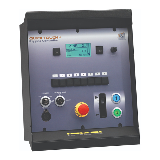
Overview QuickTouch+ control stations are designed to control Prodigy fixed speed and variable speed hoists as well as other designated 3rd party motorized devices. The QuickTouch+ control station is available in 4, 8, 12, and 24-motor configurations. T h e U s e r I n t e r f a c e Below is a graphic of a 24-motor control station. - Page 13 When a motor is selected, the motor status screen offers important information about it. The various components of the status screen are identified below. Motor Status Screen Location of High Trim Motor number Motor name Recorded load marker 300 lb Current load Current trim Trim 2:...
-
Page 14: Activate System
The contact information screen is shown as the system powers up. This screen displays contact information for the installer responsible for the system or ETC’s website and phone number. Your installer may have chosen to display their contact information. The software version is also displayed during the start up. -
Page 15: Control Motors
Control Motors S e l e c t i n g M o t o r s In order to control a motor (or motors) you must first select them using the select buttons on the control station. To select a motor press the button corresponding to the motor you wish to control. The LED for that button will illuminate white when selected. -
Page 16: Emergency Stop
It is possible to have multiple emergency stop buttons in your ETC Rigging system. All control stations are equipped with an E-stop button. In addition, you may have up to three external E- stop button stations in your system. -
Page 17: Setting Motor Speed Before A Move
S e t t i n g M o t o r S p e e d B e f o r e a M o v e Variable speed motors can be set to move at a specific speed prior to pressing the move buttons. - Page 18 QuickTouch+ Control Station User Manual...
-
Page 19: User Programmable Settings
C h a p t e r 2 User Programmable Settings In this chapter you can read about recording and using trims, recording load profiles, and load monitoring. This chapter contains the following sections: • Trims ..........16 •... -
Page 20: Trims
Trims Trims are user-programmable stopping points. If you do not record any trims, the motor will travel completely between the limits set when the system was commissioned. Each motor can have up to five trims recorded: • High trim (a user-programmable upper limit, the highest point that QT+ will allow the motor to reach) •... - Page 21 To delete a trim using the [Trim] button: Step 1: Make sure no motors are selected. Step 2: Press and release the [Trim] button. Instructions appear on the LCD to press and hold the select buttons for the desired motor(s). Step 3: Press and hold the select button(s) for the desired motor(s) for a total of 10 seconds.
-
Page 22: Moving To Trims
M o v i n g t o T r i m s Recorded trims are reached using normal motor movement, (see Moving Motors, page 12). When a moving motor reaches an intermediate trim position (Trim 1, 2, or 3) it stops movement. ... -
Page 23: Load Profiles And Monitoring
Load Profil es and Monitoring Load monitoring allows the system to verify that the correct load is being lifted. If the load is out of the allowable range, movement is stopped and an error message is displayed on the LCD. In order to monitor the load, a load profile must be “learned”... -
Page 24: Enabling Load Monitoring
Step 9: Once the new limit is reached, release the move button. Recording is complete. Step 10: Turn the keyswitch back to [RUN]. Step 11: Remove the key from the keyswitch or repeat for any other desired motors. N o t e : After removing a load from the batten that significantly changes the weight during movement, a full profile should be recorded in order to allow the lineset to function with normal loads and to facilitate Quick Learn profiles again. -
Page 25: Appendix A Status Messages
If any of these messages appear and you are not sure how to correct the situation, immediately cease use of your system and contact the ETC Rigging Installer who installed your system or contact ETC Technical Services at the appropriate office mentioned on... - Page 26 Wait for test to complete. If it does not complete, cycle power and wait for test to complete. If Self Test not done it still does not complete, contact your system installer or ETC Technical Services. Slack Cable Check to see that batten is not resting on something and that all lift lines are taut.
-
Page 27: Etc Rigging Fixed Speed Remote Control
This quick guide illustrates the integration and use of the fixed speed remote control with your ETC Rigging system. The remote control unit connects to any control station using a 7-pin XLR connector. It offers individual up and down control as well as an emergency stop button so that a motor can be run from a line-of-sight position. -
Page 28: Down
M o t o r s p e e d w h i l e u s i n g r e m o t e When using the remote control, speed of motor movement is dependent upon what type of motors are selected and, potentially, the position of the speed slider. - Page 29 Merge is an optional feature that allows you to control your system with multiple QuickTouch+ stations. Merge requires additional internal hardware for your QuickTouch+ controller. For more information contact your rigging system installer or ETC Technical Services (see page O p e r a t i o n N o t e : To control motors, all QuickTouch+ stations in the system must be powered on.
- Page 30 • The Standby message will disappear as soon as Active control is obtained. N o t e : You are not required to hold down the arrow button to obtain control at a Standby station. A single press will initiate a control request. Step 3: Once Active control is obtained, you may now control motors from the station.
- Page 32 Service: (Americas) service@etcconnect.com (UK) service@etceurope.com (DE) techserv-hoki@etcconnect.com (Asia) service@etcasia.com Web: www.etcconnect.com Copyright © 2014 ETC. All Rights Reserved. Product information and specifications subject to change. 8061M1200-1.40 Rev A Released 2014-03 ...
Need help?
Do you have a question about the QuickTouch+ 4 and is the answer not in the manual?
Questions and answers