HPE ProLiant MicroServer Gen10 Series Troubleshooting Manual
Hide thumbs
Also See for ProLiant MicroServer Gen10 Series:
- Troubleshooting manual (176 pages) ,
- User manual (145 pages) ,
- Maintenance and service manual (101 pages)
Table of Contents
Advertisement
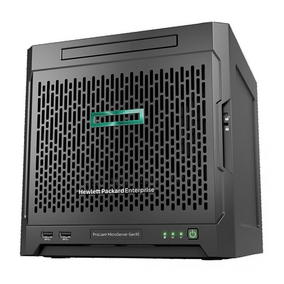
HPE ProLiant MicroServer Gen10
Troubleshooting Guide
Abstract
This document describes common procedures and solutions for troubleshooting the HPE ProLiant
MicroServer Gen10. This document is intended for the person who installs, administers, and
troubleshoots server or storage products. Hewlett Packard Enterprise assumes that you are
qualified to service computer equipment, and trained in recognizing hazards in products with
hazardous energy levels.
Part Number: 872948-002
Published: September 2017
Edition: 2
Advertisement
Table of Contents
Troubleshooting

Related Manuals for HPE ProLiant MicroServer Gen10 Series


Summary of Contents for HPE ProLiant MicroServer Gen10 Series
-
Page 1: Troubleshooting Guide
Troubleshooting Guide Abstract This document describes common procedures and solutions for troubleshooting the HPE ProLiant MicroServer Gen10. This document is intended for the person who installs, administers, and troubleshoots server or storage products. Hewlett Packard Enterprise assumes that you are qualified to service computer equipment, and trained in recognizing hazards in products with hazardous energy levels. - Page 2 © Copyright 2017 Hewlett Packard Enterprise Development LP Notices The information contained herein is subject to change without notice. The only warranties for Hewlett Packard Enterprise products and services are set forth in the express warranty statements accompanying such products and services. Nothing herein should be construed as constituting an additional warranty. Hewlett Packard Enterprise shall not be liable for technical or editorial errors or omissions contained herein.
-
Page 3: Table Of Contents
Symptom information.........................24 Preparing the server for diagnosis.....................25 Minimum hardware configuration...................... 25 Breaking down the server to minimum hardware configuration..........25 DIMM population information......................25 HPE SmartMemory speed information....................26 DIMM handling guidelines......................... 26 DIMM installation guidelines......................26 Hardware issues..................27 General hardware issues........................27 Loose connections........................27... - Page 4 Third-party device issues......................28 Power issues............................. 29 Server does not power on.......................29 Power supply issues....................... 29 Power source issues.......................30 UPS issues..........................30 Internal system issues........................31 Fan and thermal issues......................31 Trusted Platform Module issues..................... 33 Memory issues........................34 System board issues......................37 System battery is low or has lost power.................
- Page 5 HPE Smart Storage Administrator ....................60 USB support ............................. 60 Keeping the system current.......................60 Firmware ..........................60 Firmware update........................61 Drivers, firmware, and software updates ................62 Operating System Version Support..................62 HPE Pointnext Portfolio......................62 Proactive notifications......................62 Resources for troubleshooting..............64 Online resources..........................64 Hewlett Packard Enterprise Information Library..............
-
Page 6: Getting Started
Getting started Important safety information Familiarize yourself with the safety information in the following sections before troubleshooting the system. Important safety information Before servicing this product, read Safety and Compliance Information for Server, Storage, Power, Networking, and Rack Products on the Hewlett Packard Enterprise website. Symbols on equipment The following symbols might be found on the equipment to indicate the presence of potentially hazardous conditions. -
Page 7: Server Warnings And Cautions
Server warnings and cautions WARNING: To reduce the risk of personal injury, electric shock, or damage to the equipment, disconnect the power cord to remove power from the server. Pressing the Power On/Standby button does not shut off system power completely. Portions of the power supply and some internal circuitry remain active until AC power is removed. - Page 8 • Use a wrist strap connected by a ground cord to a grounded workstation or computer chassis. Wrist straps are flexible straps with a minimum of 1 megohm ±10 percent resistance in the ground cords. To provide proper ground, wear the strap snug against the skin. •...
-
Page 9: Component Identification
Component identification This chapter describes the external and internal server features and components. Front panel components Item Component Description Drive bays (4, behind the front By default, the drive bays support 3.5-inch LFF SATA drives. bezel) To support 2.5-inch SFF drives, install the SFF drive converter option. -
Page 10: Front Panel Leds And Buttons
Front panel LEDs and buttons Item Description Status Drive activity LED Flashing green = Ongoing drive activity Off = No drive activity This LED only reflects the status of LFF/SFF drives and SSD that are connected to the onboard SATA ports. NIC status LED Solid green = Linked to network Flashing green = Network active... -
Page 11: Health Led Warning Conditions
If the server does not power on, verify the following items: • The site power is available. • The power cord is properly connected to the server power jack and to a working power source. • The internal power supply cable is properly connected to the system board. Health LED warning conditions Health LED warning condition Cause... - Page 12 Item Component Description Power jack Connects the power cord. Expansion slot 2, PCIe3 ×4 (1) For additional hardware capabilities, install a compatible low‑profile PCIe expansion board here. This expansion slot supports expansion boards with a physical connector link widths of up to ×16. Expansion slot 1, PCIe3 ×8 (8, 4, 1) For additional hardware capabilities, install a compatible low‑profile PCIe expansion board here.
-
Page 13: Rear Panel Leds
Rear panel LEDs Item Description Status NIC link LED Solid green = Link exists Off = No link exists NIC status LED Solid green = Linked to network Flashing green = Network active Off = No network activity System board components Rear panel LEDs... -
Page 14: Dimm Slot Locations
Item Component Description Connects the fan cable. Fan connector These slots support standard UDIMMs with ECC only. DIMM slots Use the jumper on this header to clear the CMOS. CMOS header This connector supports the TPM 2.0 option for data security solution. TPM connector LFF/SFF drive SATA port Connects the LFF/SFF drive SATA cable. - Page 15 Component identification...
-
Page 16: Basic Operations
Basic operations Power up the server Press the Power On/Standby button. The server exits standby mode and applies full power to the system. The system power LED changes to green. Power down the server Prerequisites Before powering down the server for any upgrade or maintenance procedures, perform a backup of critical server data and programs. -
Page 17: Removing An Unlocked Front Bezel
2. Open the front bezel. The front bezel is a removable part. Opening the bezel will loosen it from the front panel. 3. To completely detach the bezel from the front panel, pull the bezel hinges from the chassis. Retain the bezel for later use. Removing an unlocked front bezel Prerequisites 1. -
Page 18: Install The Front Bezel
The front bezel is a removable part. Opening the bezel will loosen it from the front panel. 2. To completely detach the bezel from the front panel, pull the bezel hinges from the chassis. Retain the bezel for later use. Install the front bezel To cover the drive bays, install the front bezel. -
Page 19: Remove The Chassis Cover
c. Install the chassis cover on page 19. Remove the chassis cover To access the front bezel lock and the internal components, remove the chassis cover. Procedure 1. If installed, unlock and remove the security padlock and/or the Kensington security lock. For more information, see the lock documentation. -
Page 20: Install The Chassis Cover
Install the chassis cover Prerequisites 1. Verify that all internal cables are properly connected and are secured in their respective cable ties. 2. Verify that the drive cables are not blocking the fan blades. Procedure 1. Insert the tabs on the bottom left and right sides of the chassis cover into the corresponding slots on the chassis. -
Page 21: Remove The System Board Assembly
4. Connect the following system cables: • Power supply cable • Optical drive or SSD SATA cable (optional) • LFF/SFF drive SATA cable – This cable can either be connected to the system board or to an installed HBA. • Fan cable 5. -
Page 22: Remove The System Board Assembly
Remove the system board assembly Prerequisites Before you perform this procedure, make sure that you have a T-15 Torx screwdriver available. Procedure 1. If installed, remove the internal USB device. 2. To serve as a reference for system cable connections when the system board assembly is installed back into the server, take a picture of the current system board cable connections. - Page 23 Basic operations...
-
Page 24: Troubleshooting Preparation
Troubleshooting preparation Preparing to troubleshoot Procedure 1. Review the important safety information. 2. Gather and record symptom information. 3. Gather all materials necessary to troubleshoot, such as a Torx screwdriver, loopback adapters, ESD wrist strap, and software utilities. Symptom information The following list of questions can help to identify a specific issue. -
Page 25: Preparing The Server For Diagnosis
Gen10 memory user guide. • Hard drives and solid-state drives • Optical drives (DVD-ROM, CD-ROM, and so forth) • Expansion boards DIMM population information For specific DIMM population information, use the HPE Server Memory Configurator tool (https:// www.hpe.com/servers/servermemoryconfigurator). Preparing the server for diagnosis... -
Page 26: Hpe Smartmemory Speed Information
HPE SmartMemory speed information For more information about memory speed information, see the Hewlett Packard Enterprise website (https:// www.hpe.com/docs/memory-speed-table). DIMM handling guidelines When handling a DIMM, observe the following guidelines: • Avoid electrostatic discharge. • Always hold DIMMs by the side edges only. -
Page 27: Hardware Issues
Action Verify that the hardware being installed is supported on the server. If the hardware is not supported, remove the hardware. For more information on supported hardware, see the product QuickSpecs on the HPE ProLiant MicroServer Gen10 website: http://www.hpe.com/servers/microserver Verify that a change to the hardware release did not cause the issue. -
Page 28: Third-Party Device Issues
After installing or replacing boards or other options, verify that the system recognizes all changes to the hardware in the Aptio Setup Utility. If the new hardware is not configured properly, a POST error message might display, indicating a configuration error. 10. -
Page 29: Power Issues
Power issues Server does not power on Symptom The server will not power on. Cause • The power cord or internal power supply cable might not be securely connected. • Issues might exist with the power supply or power source. •... -
Page 30: Power Source Issues
For more information, see Loose connections. 2. Verify that the power supply is supported on the server. 3. Check the system power LED to see if it indicates an issue. • If the system power LED is red, replace the power supply. •... -
Page 31: Internal System Issues
Action 1. Verify that the UPS batteries are charged to the proper level for operation. For more information, see the UPS documentation. 2. Verify that the UPS power switch is in the On position. For the location of the switch, see the UPS documentation. - Page 32 • The fan cable is not properly connected. • The server is not properly ventilated. Action 1. Verify that no loose connections exist. For more information, see Loose connections. 2. Check the front panel LEDs to see if any LEDs indicate an issue. For more information, see Front panel LEDs and buttons.
-
Page 33: Trusted Platform Module Issues
Recovery Mode after BitLocker detects a possible compromise of system integrity. • HPE is not liable for blocked data access caused by improper TPM use. For operating instructions, see the encryption technology feature documentation provided by the operating system. -
Page 34: Memory Issues
CAUTION: Any attempt to remove an installed TPM from the system board breaks or disfigures the TPM security rivet. Upon locating a broken or disfigured rivet on an installed TPM, consider the system compromised and take appropriate measures to ensure the integrity of system data. Memory issues General memory issues Cause... - Page 35 An unsupported DIMM is installed in the server. Action 1. Verify that the DIMMs are supported on the server. For a list of supported options, see the product QuickSpecs on the HPE ProLiant MicroServer Gen10 website: http://www.hpe.com/servers/microserver 2. Verify that the DIMMs are installed according to the DIMM population information.
- Page 36 For a list of supported options, see the product QuickSpecs on the HPE ProLiant MicroServer Gen10 website: http://www.hpe.com/servers/microserver 2. Verify that the DIMM is installed according to the server requirements. For more information, see DIMM population information. 3. Verify that you have not exceeded the memory limits of the server or operating system.
-
Page 37: System Board Issues
Action 1. Update the system ROM. For more information, see Keeping the system current. 2. Replace the DIMM. For more information, see the maintenance and service guide in the Hewlett Packard Enterprise Information Library. Uncorrectable memory error Symptom • A POST error message displays •... -
Page 38: System Battery Is Low Or Has Lost Power
Remove the system battery for 10 minutes. Then, reinstall the battery and power on the server. To locate the system battery, see System board components. 5. Reset the BIOS configuration settings to default. For more information, see Restoring and customizing configuration settings. 6. - Page 39 Marvell BIOS Utility. • If the drives are connected to a Smart Array storage controller, use the HPE Smart Storage Administrator. 8. Verify that the replacement drives within an array are the same size or larger and are the same drive type, such as SAS, SATA, or SSD.
-
Page 40: Usb Drive Key Issues
For more information, see the operating system documentation. 3. If you are using a Smart Array storage controller, use HPE SSA to verify that a recovery operation is not pending on the logical drive. For more information, see HPE Smart Storage Administrator. - Page 41 3. Verify that the media from which you are attempting to boot is not damaged and is a bootable CD-ROM or DVD drive. 4. If you are attempting to boot from an external USB CD-ROM or DVD drive, see the operating system and server documentation to verify that booting from an external USB CD-ROM or DVD drive is supported.
-
Page 42: Tape Drive Issues
For more information, see the Storage section of the Hewlett Packard Enterprise Information Library. To download the HPE Library and Tape Tools (L&TT), see the Hewlett Packard Enterprise website. Tape drive does not eject Symptom The tape drive is stuck and will not eject. - Page 43 The tape drive backup fails to complete without issues. Action 1. Run the Drive Assessment Test in HPE Library and Tape Tools. Running the Drive Assessment Test overwrites the tape. If it is not possible to overwrite the tape, run the logs-based Device Analysis Test instead.
-
Page 44: External Device Issues
External device issues Video issues Screen is blank for more than 60 seconds after powering up the server Symptom The screen is blank for more than 60 seconds after the server is powered up. Cause • The monitor is not receiving power. •... -
Page 45: Mouse And Keyboard Issues
Action Verify that the monitor supports energy saver features. If the monitor does not support energy saver features, disable the features. Video colors do not display correctly Symptom The video colors do not correctly display on the monitor. Cause • The video cable is not securely connected to the correct port. -
Page 46: Network Controller Issues
Observe whether the keyboard lights flash at POST or the Num Lock LED illuminates. If not, change the port connections. 7. Clean the keyboard or mouse. 8. Replace the device with a known working equivalent device (a similar mouse or keyboard). Verify that the device is connected to the same USB connector on the front/rear panel as the original device. - Page 47 3. Verify that the correct cable type is used for the network speed or that the correct SFP or DAC cable is used. For dual-port 10GB network devices, both SFP ports should have the same media (for example, DAC cable or equivalent SFP+ module). Mixing different types of SFP (SR/LR) on a single device is not supported.
-
Page 48: Expansion Board Issues
Expansion board issues System requests recovery method during expansion board replacement Symptom The system request a recovery method while the expansion board is being replaced on a BitLocker-encrypted server. Action Verify that BitLocker was disabled before replacing the expansion board. When replacing an expansion board on a BitLocker-encrypted server, always disable BitLocker before replacing the expansion board. - Page 49 Error message Description Error: Thermal temperature condition has been Either the environmental temperature or the internal degraded, the system may or may not shut down system temperature has triggered a warning depending on thermal shutdown setting. condition. If the Thermal Shutdown option is enabled in the Aptio Setup Utility, the system will automatically initiate a graceful shutdown to protect the system.
-
Page 50: Software Issues
Software issues Operating system issues and resolutions Operating system issues Operating system locks up Symptom The operating system locks up. Action Scan for viruses with an updated virus scan utility. Errors are displayed in the error log Symptom Error messages are displayed in the error log. Action Follow the information provided in the error log. -
Page 51: Prerequisites For Reconfiguring Or Reloading Software
For troubleshooting information specific to Linux operating systems, see the Linux for ProLiant website. To assist in possible LINUX installation issues on HPE ProLiant servers, capture either the sosreport or supportconfig before contacting Hewlett Packard Enterprise technical support. For more information, see Linux tools (sosreport and supportconfig). -
Page 52: Errors Occur After A Software Setting Is Changed
Cause • The software might be incompatible with other software on the server. • Known issues might exist with the software. • The server configuration might have changed. • The server might be infected by a virus. Action 1. Check the application log and operating system log for entries indicating why the software locked up. 2. -
Page 53: Rom Issues
ROM issues System requests recovery method during a firmware update Symptom The system requests a recovery method during a firmware update. Action 1. When updating the firmware on a BitLocker-encrypted server, do the following: a. Always disable BitLocker before updating the firmware. If BitLocker is not disabled, the system requests the recovery method selected when BitLocker was configured. -
Page 54: Software Tools And Solutions
Offline Product QuickSpecs For more information about product features, specifications, options, configurations, and compatibility, see the product QuickSpecs on the HPE ProLiant MicroServer Gen10 website: http://www.hpe.com/servers/microserver Aptio Setup Utility The Aptio Setup Utility is embedded in the system ROM. This utility enables you to perform a wide range of configuration activities, including the following: •... -
Page 55: Boot Option Control
Default configuration settings are sufficient for typical server operations. However, you can modify the configuration settings as needed. The system prompts you to access the Aptio Setup Utility every time the system is powered up. Boot option control This feature enables you: •... - Page 56 • Incorrect settings made in the Aptio Setup Utility have caused error messages to be unreadable. • If there is a hardware compatibility issue of a known compatible component. • If the power-on password is forgotten. CAUTION: Be careful when clearing or altering the BIOS settings. Changing some settings might prevent the server from booting up correctly or might result in data loss.
-
Page 57: Embedded Uefi Shell
After five seconds, remove the jumper from pins 1 and 2, and move it back to the default position on pins 2 and 3. Install the system board assembly on page 20. Install the chassis cover on page 20. 10. Connect all peripheral cables to the server. 11. -
Page 58: Secure Boot Configuration
To enable MSU access through GUI or CLI, install the MSU in the server. For more information, see the Marvell Storage Utility User Guide for HPE MicroServer Gen10 in the Hewlett Packard Enterprise Support Center website: http://www.hpe.com/info/microservergen10-docs... -
Page 59: Marvell Bios Utility
RAID virtual disks and arrays using the drives connected to the embedded storage controller. For more information, see the Marvell BIOS Utility User Guide for HPE MicroServer Gen10 in the Hewlett Packard Enterprise Support Center website: http://www.hpe.com/info/microservergen10-docs Accessing the Marvell BIOS Utility under UEFI boot mode The UEFI boot mode is the server default boot mode. -
Page 60: Hpe Smart Storage Administrator
Although all formats support configuration tasks, some of the advanced tasks are available in only one format. In this server, HPE SSA can be accessed in both online and offline modes. In online mode, SSA is only accessible from the local server. -
Page 61: Firmware Update
Procedure Access the System ROM Flash component for your server from the Hewlett Packard Enterprise Support Center website (http://www.hpe.com/support/hpesc) and save the package in a USB key. Copy the file to a USB device. Attach the USB device to the server. -
Page 62: Drivers, Firmware, And Software Updates
HPE Pointnext Portfolio HPE Pointnext delivers confidence, reduces risk, and helps customers realize agility and stability. Hewlett Packard Enterprise helps customers succeed through Hybrid IT by simplifying and enriching the on-premise experience, informed by public cloud qualities and attributes. - Page 63 • Hardware, firmware, and software changes • Bulletins • Patches • Security alerts You can subscribe to proactive notifications on the Hewlett Packard Enterprise website. Software tools and solutions...
-
Page 64: Resources For Troubleshooting
Hewlett Packard Enterprise PartSurfer website: • Desktop: http://www.hpe.com/info/partssurfer • Mobile: http://partsurfermobile.ext.hpe.com Teardown or removal and replacement procedure videos For more information about removal and replacement procedures for HPE ProLiant servers, see the Hewlett Packard Enterprise website. Resources for troubleshooting... -
Page 65: Ddr4 Memory Configuration
DDR4 memory configuration Locate the DDR4 Smart Memory Configurator on the Hewlett Packard Enterprise website. Device driver information See the device driver information on the Hewlett Packard Enterprise website. DDR4 memory configuration... -
Page 66: Websites
Single Point of Connectivity Knowledge (SPOCK) Storage compatibility matrix www.hpe.com/storage/spock Storage white papers and analyst reports www.hpe.com/storage/whitepapers For additional general support websites, see Support and other resources. Product websites Product QuickSpecs http://www.hpe.com/servers/microserver HPE ProLiant MicroServer Gen10 support page http://www.hpe.com/support/microservergen10 HPE ProLiant MicroServer Gen10 documents http://www.hpe.com/info/microservergen10-docs Websites... -
Page 67: Support And Other Resources
North America: +1-800-977-0574 ◦ International: +1-801-851-5555 • Email: support@clearcenter.com For more information on ClearOS configuration, see the ClearOS 7 on HPE ProLiant Servers Configuration Guide at: http://www.hpe.com/support/ClearOS-IG Accessing updates • Some software products provide a mechanism for accessing software updates through the product interface. -
Page 68: Customer Self Repair
IMPORTANT: Access to some updates might require product entitlement when accessed through the Hewlett Packard Enterprise Support Center. You must have an HPE Passport set up with relevant entitlements. Customer self repair Hewlett Packard Enterprise customer self repair (CSR) programs allow you to repair your product. If a CSR part needs to be replaced, it will be shipped directly to you so that you can install it at your convenience. - Page 69 (docsfeedback@hpe.com). When submitting your feedback, include the document title, part number, edition, and publication date located on the front cover of the document. For online help content, include the product name, product version, help edition, and publication date located on the legal notices page.
-
Page 70: Acronyms And Abbreviations
Customer Self Repair direct attach cable DDR4 double data rate-4 electrostatic discharge host bus adapter HPE SSA HPE Smart Storage Administrator International Organization for Standardization kernel-based virtual machine large form factor long reach PCIe Peripheral Component Interconnect Express POST... - Page 71 small form-factor pluggable short range solid state drive Trusted Platform Module UEFI Unified Extensible Firmware Interface uninterruptible power supply Acronyms and abbreviations...
Need help?
Do you have a question about the ProLiant MicroServer Gen10 Series and is the answer not in the manual?
Questions and answers