Table of Contents
Advertisement
Quick Links
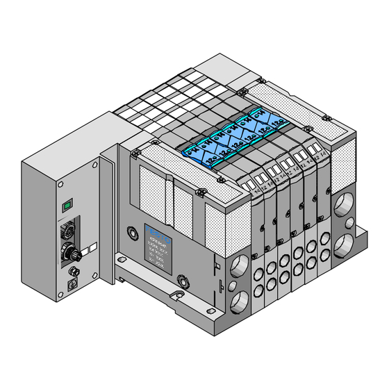
Compact Performance
AAAA
AAAA
AA
AAAA
AAAA
AA AA
AAAA
AAA
AAAA
AAAA
AAA
AA AA
AAAA
AA AA
AAAA
AAA
AAA
AAAA
AAAA
AAA
AA AA
AAA
AAAA
AAA
AAAA
AA AA
AAAA
AAA
AAA
AAAA
AAA
AAAA
AAA
AA AA
AAA
AAA
AAAA
AAA
AAA
AAA
AAAA
AAA
AAA
AAAA
AAA
AAAA
AAA
AAAA
AAAA
AAAA
AAAA
AAAA
AAAA
AAAA
AAAA
AAAA
AAAA
AAAA
AAAA
AAAA
AA
AAA
AAAA
AAAA
AAAA
AA AA
AAA
AAAA
AAAA
AAAA
AAA
AAAA
AAA
AAAA
AA AA
AAA
AAA
AAAA
AAA
AAA
AAA
AAA
AAA
AAA
Typ CPA..-VI
CPA Valve terminal
Pneumatics
AAAA
AAAA
AAA
AAAA
AAAA
AAA
AAAA
AAAA
AAAA
AAA
AAAA
AAAA
AAA
AAAA
AAA
AAAA
AAAA
AAA
AAAA
AAA
AAAA
AAAA
AAA
AAAA
AAA
AAA
AAA
AAAA
AAA
AAA
AAA
AAAA
AAA
AAA
AAA
AAA
AAA
AAA
AAA
AAA
AAA
AAA
AAAA
AAAA
AA AA
AAAA
AAAA
AAAA
AAAA
AA AA
AAAA
AAAA
AAAA
AAAA
AA AA
AAA
AAAA
AAAA
AAA
AAAA
AAA
AAA
AAAA
AAA
AAA
AAAA
AAA
AAA
AAAA
AAA
AAA
AAAA
AAA
AAA
AAA
AAAA
AAA
AAA
AAA
AAA
AAA
AAA
AAA
AAAA
AAAA
AA
AAAA
AAAA
AA
AAAA
AAAA
AA AA
AAAA
AAAA
AAAA
AAAA
AA
AAAA
AAAA
AAAA
AA AA
AAAA
AAAA
AAA
AAAA
AAAA
AAA
AAAA
AAAA
AAAA
AAA
AAA
AAAA
AAAA
AAAA
AAAA
AAA
AAA
AAAA
AAAA
AAAA
AA AA
AAAA
AAA
AAA
AAAA
AAAA
AAAA
AAA
AAAA
AAA
AAA
AAAA
AAAA
AAAA
AAA
AA AA
AAAA
AAA
AAA
AAAA
AAA
AAAA
AAAA
AAA
AAA
AAAA
AAAA
AA AA
AAA
AAA
AAAA
AAA
AAA
AAAA
AAA
AAA
AAAA
AAA
AAAA
AAAA
AAAA
AAA
AAAA
AAAA
AAA
AAAA
AAAA
AAA
AAAA
AAAA
AAAA
AAA
AAAA
AAA
AAAA
AAAA
AAAA
AAA
AAAA
AAA
AAAA
AAAA
AAAA
AAAA
AAA
AAAA
AAA
AAA
AAA
AAAA
AAAA
AAA
AA AA
AAAA
AAA
AAA
AAA
AAAA
AAAA
AAA
AAAA
AAA
AAA
AAA
AAAA
AAAA
AAA
AA AA
AAAA
AAA
AAAA
AAA
AAA
AAA
AAAA
AAA
AAA
AAAA
AAA
AAA
AAAA
AAA
AA AA
AAA
AAAA
AAA
AAA
AAA
AAA
AAAA
AAA
AAA
AAAA
AAA
AAAA
Advertisement
Table of Contents

Related Manuals for Festo CPA VI Series


Summary of Contents for Festo CPA VI Series
- Page 1 Compact Performance CPA Valve terminal Pneumatics AAAA AAAA AAAA AAAA AAAA AAAA AAAA AAAA AAAA AAAA AAAA AAAA AAAA AAAA AAAA AAAA AA AA AAAA AAAA AAAA AAAA AAAA AAAA AAAA AAAA AAAA AAAA AAAA AAAA AAAA AAAA AA AA AAAA AAAA AAAA...
- Page 3 Festo, Dept. KI-TD Type setting: KI-TD Edition: 9808A © (Festo AG & Co., D-73726 Esslingen, Federal Republic of Germany, 1998) The copying, distribution and utilization of this docu- ment as well as the communication of its contents to others without expressed authorization is prohibited. Of- fenders will be held liable for the payment of damages.
- Page 4 Order no.: 173 515 Title: MANUAL Designation: P.BE-CPA-GB CPA.. 9808A...
-
Page 5: Table Of Contents
Contents Designated use ..........V Target group . - Page 6 A. Technical appendix Festo-Accessories ........A-3 Technical specifications .
-
Page 7: Designated Use
Festo: – according to designated use – in their original state – without modifications by the customer –... -
Page 8: Important User Instructions
Important user instructions Danger This manual contains instructions on the possible categories dangers which may occur if the CPA valve terminal is not used correctly. These instructions are printed in italics, are placed in a frame and are also marked with pictograms. - Page 9 Pictograms Pictograms and symbols supplement the danger in- structions and draw the user’s attention to the nature of the dangers and their consequences. The following pictograms are used: Uncontrolled movements of loose tubing. Unexpected movements of the connected actuators. Hight electric voltage or undefined voltage states of the electronic components with subsequent effects in con- nected circuits.
-
Page 10: Notes On This Manual
Notes on this manual This manual contains specific information on fitting, in- stalling, commissioning, servicing and converting the CPA valve terminal. The manual deals only with the pneumatic components and refers to the valve terminal variants listed in the following table: Variants of the CPA valve terminal type CPA..-VI with individual connection (IC connection) with multipin connection (MP connection) - Page 11 Manuals on the CP system Peripherals Manual "CP system, installation and commissioning" Content General, basic information on the method of operation, fitting, installation and commissioning of CP systems. Manual "CP field bus node, "CPA valve "CP modules, programming and terminal, electronics"...
- Page 12 The CPA valve terminal consists of a combination of different plates. The main components of the CPA valve terminal are the valve plates, sub-bases and end plates (see diagram). AAAA AAAA AAAA AAAA AAAA AAAA AAAA AAAA AAAA AAAA AA AA AAAA AAAA AAAA...
-
Page 13: Product-Specific Terms And Abbreviations
Product-specific terms and abbreviations The following product-specific terms and abbreviations are used in this manual Term Meaning Additional pres- Plate for supplying pressure zones in the centre of the CPA valve sure supply plate terminal. In this plate the compressed air is taken from work connection 2 so that the appropriate valve plates are supplied with compressed air. - Page 14 Term Meaning Components Common term for pneumatic sub-bases, valve plates, additional pressure supply plates, reserve plates, end plates, electrical sub-bases (with IC, MP, CP or AS-i connections), electrical manifold bases, sub-bases, end plate covers, silencers. Electrical bridge Conducts the supply voltage from the manifold base to the solenoid coils on CPA valve terminals with MP, CP or AS-i connections.
-
Page 15: System Summary
1. System summary Chapter 1 System summary CPA... 9808A... - Page 16 1. System summary Contens 1. System summary Summary of variants........1-3 Description of the components.
-
Page 17: Summary Of Variants
1. System summary 1.1 Summary of variants Festo supports your automation task at the machine level with CPA valve terminals. The modular structure of the CP system enables you to optimally integrate the CPA valve terminals and I/O modules in your machine or system. - Page 18 1. System summary CPA valve ter- The CPA valve terminals are available with the following minal types of electrical connections: variants MP connection IC connection AAAA AAAA AAAA AAAA AAAA AAAA AAAA AAAA AAAA AAAA AAAA AAAA AAAA AAAA AAAA AAAA AAAA AAAA...
- Page 19 1. System summary CPA valve ter- This CPA valve terminal is available with 2 to max. 22 minal with single solenoid valves or 11 double solenoid valve loca- MP con- tions. Max. 22 valve coils can be controlled. The electri- nection cal connection for the valve solenoid coils is made cen- trally via the multipin plug.
-
Page 20: Description Of The Components
1. System summary 1.2 Description of the components The CPA valve terminal consists of the following com- ponents: " AAAA AAAA AAAA AAAA AAAA AAAA AAAA AAAA AAAA AAAA AA AA AAAA AAAA AAAA AAAA AAAA AAAA AAAA AAAA AAAA AAAA AAAA AAAA... - Page 21 1. System summary The table below shows the max. number of valve loca- tions on the CPA valve terminals: CPA valve terminal Max. no. of valve locations AS-i connection connection connection connection For use only with manifold block EV1 (for valve plate with 1 single solenoid valve) For use only with manifold block EV2 (for valve plate with 2 single solenoid...
- Page 22 1. System summary Observe the designatons of the control sides on the fol- lowing switching symbols: • • all valves: left hand side on symbol with 14 or 140 (140 means that in switch position the flow from compressed air supply 1 to output 4 is blocked).
- Page 23 1. System summary Valve plates 82/84 Ident. code: K Function: - two single solenoid 3/2-way valves, basic position blocked 12/14 Ident. code: H 82/84 Function: - one single solenoid 3/2-way valve, basic position blocked and one single solenoid 3/2-way valve, basic position open.
- Page 24 1. System summary The following pneumatic connections and operating ele- ments are to be found on the CPA valve terminal: CPA valve terminal with CPA valve terminal with MP-, CP- oder AS-i IC connection connection AAAA AAAA AAAA AAAA AAAA AAAA AAAA AAAA...
- Page 25 1. System summary The following electrical connections and display ele- ments are to be found on the CPA valve terminal with IC connection: " AAAA AAAA AAAA AAAA AAAA AAAA AA AA AAAA AAAA AAAA AAAA AAAA AAAA AAAA AAAA AAAA AAAA AAAA...
- Page 26 1. System summary The following electrical connections and display ele- ments are to be found on the CPA valve terminal with MP connection: AAAA AAAA AAAA AAAA AAAA AAAA AAAA AAAA AAAA AAAA AAAA AAAA AAAA AAAA AAAA AAAA AAAA AAAA AAAA AAAA...
- Page 27 1. System summary The following electrical connections and display ele- ments are to be found on the CPA valve terminal with CP connection: AAAA AAAA AAAA AAAA AAAA AAAA AAAA AAAA AAAA AA AA AAAA AAAA AAAA AAAA AAAA AAAA AAAA AAAA AAAA...
- Page 28 1. System summary The following electrical connections and display ele- ments are to be found on the CPA valve terminal with AS-i connection: & AAAA AAAA AAAA AAAA AAAA AAAA AAAA AAAA AAAA AAAA AAAA AAAA AAAA AAAA AAAA AAAA AAAA AAAA AAAA...
-
Page 29: Fitting
2. Fitting Chapter 2 Fitting CPA... 9808A... - Page 30 2. Fitting Contents 2. Fitting Fitting variants ........2-3 2.1.1 Fitting onto a wall .
-
Page 31: Fitting Variants
2. Fitting WARNING Before undertaking installation or maintenance work, switch off the following power supplies: • the compressed air supply • the voltage supply for the valve solenoid coils You can thereby avoid: – uncontrolled movements of loose tubing – undesired movements of the connected actuators –... -
Page 32: Fitting Onto A Wall
2. Fitting 2.1.1 Fitting onto a wall Proceed as follows: 1. Make sure that the mounting surface can support the CPA valve terminal. 2. Make sure that there is sufficient space for connect- ing the supply cables and pneumatic tubing. 3. -
Page 33: Fitting Onto A Hat Rail
2. Fitting 2.1.2 Fitting onto a hat rail In order to fit the CPA valve terminal onto a hat rail you will require mounting kit CPA10/14-BG-NRH. This kit consists of two M4x10 screws and two clamping el- ements. Proceed as follows: 1. - Page 34 2. Fitting 4. Fit the hat rail clamping units onto the end plates of the CPA valve terminal (see diagram). 5. Hang the CPA valve terminal onto the upper part of the hat rail (see arrow A). 6. Swing the CPA valve terminal onto the lower part of the hat rail (see arrow B).
-
Page 35: Installation
3. Installation Kapitel 3 Installation CPA... 9808A... - Page 36 3. Installation Contents 3. Installation General connecting principles ......3-3 Connecting the CPA valve terminal ..... . 3-5 3.2.1 Auxiliary pilot air .
-
Page 37: General Connecting Principles
3. Installation 3.1 General connecting principles WARNING Before undertaking installation or maintenance work, switch off the following power supplies: • the compressed air supply • the voltage supply for the valve solenoid coils You can thereby avoid: – uncontrolled movements of loose tubing –... - Page 38 3. Installation Basic instructions – Connecting 1. Push tube (B) as far as possible into the tube of the pin-type connectoror into the screw connector. If necessary, press down locking ring (A). 2. Group the tubing together for a clearer overview of the system using either: - tube straps or - multiple hose holders...
-
Page 39: Connecting The Cpa Valve Terminal
3. Installation 3.2 Connecting the CPA valve terminal Seal the work connections (2 or 4) with blind plugs or threaded blind plugs on sub-bases fitted with reserve plates. To guarantee the optimum performance of your CPA valve terminal, we recommend that the compressed air and, if necessary, the exhaust tubing be connected on both sides in the flowing cases: –... - Page 40 3. Installation Internal If the supply pressure of your CPA valve terminal lies auxiliary between 3 and 8 bar, you can operate it with internally pilot air branched auxiliary pilot air. The auxiliary pilot air is taken from connection 1 in the right-hand end plate. If the CPA valve terminal is used with internal auxiliary pilot air, the centre connection must be sealed with a blind plug or threaded blind plug (see diagram).
- Page 41 3. Installation External If the supply pressure of your CPA valve terminal does auxiliary not lie between 3 and 8 bar, you must operate it with pilot air external auxiliary pilot air. The auxiliary pilot air is sup- plied here externally via connection 12/14. PLEASE NOTE •...
- Page 42 3. Installation " Control pressure 12/14 [bar] Working pressure P1 [bar] " Startup control pressure Reset control pressure Fig. 3/4: Auxiliary pilot air diagram for CPA14 valve plates with Ident. code N, K or H Please note that the regulated external auxiliary pilot air for all the valve plates on the CP terminal is supplied is taken via common tubing on the right-hand end plate.
-
Page 43: Cpa Valve Terminal With Separation Of Pressure Zones
3. Installation 3.2.2 CPA valve terminal with separation of pressure zones The CPA valve terminal can be fitted with the following number of pressure zones, depending on the con- nection variant: Electrical connection IC or MP AS-i variant Number of pressure zones 1 - 12 1 - 9 1 - 3... - Page 44 3. Installation CPA valve terminals with more than two pressure zones A sub-base with separation of the pressure zones is required for each pressure zone. The outer pressure zones are supplied with compressed air via the end plates (connection 1); further pressure zones are sup- plied via sub-bases (connection 2) which are equipped with additional pressure supply plates (see diagram).
-
Page 45: Connecting The Supply, Exhaust And Work Lines
3. Installation 3.2.3 Connecting the supply, exhaust and work lines Fit the screw connectors as described below. Then con- nect the tubing. Proceed as follows: 1. Use the table below in order to select the correct pin-type inserts. Connec- Line CPA10 terminal CPA14 terminal tion code... - Page 46 3. Installation 2. Check to see if the seal of the pin-type insert is greased. If necessary, grease the seal with Festo F2 or Esso Beacon grease. 3. Press the pin-type inserts into the connecting holes. 4. Check to see if the pin-type inserts are seated as far as possible in the holes.
- Page 47 3. Installation 5. Secure the pin-type inserts with the clamping springs (see diagram). AAAA AAAA AAAA AAAA AAAA AAAA AA AA AAAA AAAA AAAA AAAA AAAA AAAA AAAA AAAA AAAA AAAA AAAA AAAA AAAA AAAA AAAA AAAA AAAA AAAA AA AA AAAA AAAA AAAA...
- Page 48 3. Installation Please observe the following instructions on installing the pneumatic components. Only in this way will fault- less operation be guaranteed. – If you have several systems with centrally ducted exhaust, use non-return valves in the common ex- haust lines in order to avoid malfunctioning due to back pressures.
- Page 49 3. Installation Vacuum/low pressure operation The CPA valve terminal can be operated with vacuum or low pressure >-0.9 to < 3 bar under the following conditions: – regulated auxiliary pilot air must be supplied sepa- rately – the CPA valve terminal must be fitted with the following valve plates: -5/2-way valve, single solenoid (type M) -5/2-way valve, double solenoid (type J)
-
Page 50: Connecting The Electric Cables
EN 60950 / VDE 0805. Remark: Protection against electric shock (protection against di- rect and indirect contact) is guaranteed on Festo valve terminals by the use of PELV power units in accord- ance with EN 60204-1 / IEC 204. The valve terminals must be earthed in order to ensure their function (e.g. - Page 51 With this CPA valve terminal variant, each valve sole- noid coil is connected separately. Use the ready-to-use sockets of type KMYZ-4-24-... or KMYZ-5-24-...-LED from Festo for connecting the valve solenoid coils. In the transparent plug of socket KMYZ-5-24-...-LED there is an LED which indicates the switching status of the valve solenoid coils.
- Page 52 3. Installation Connect the valve solenoid coils as follows: 1. Place the intermediate plug on the terminal lug of the appropriate pilot solenoid for current reduction. 2. Place the socket on the terminal lug of the appropri- ate pilot solenoid. The socket can be turned 180 Make sure that the centring bolt fits between the ter- minal lugs and into the hole in the socket (see diag- ram).
- Page 53 CPA valve terminals with MP or AS-i connection Connecting the MP or AS-i cable Detailed instructions on connecting the CPA valve ter- minal with multipin or AS-i connections can be found on the information sheet supplied with the product. CPA valve terminals with CP connection Connecting the CP cable Detailed instructions on connecting the CPA valve ter- minal with CP connection can be found in the manual...
- Page 54 3-20 CPA... 9808A...
-
Page 55: Commissioning
4. Commissioning Chapter 4 Commissioning CPA... 9808A... - Page 56 4. Commissioning Contents 4. Commissioning Commissioning and testing the valves....4-3 Locating faults........4-11 CPA...
-
Page 57: Commissioning And Testing The Valves
4. Commissioning 4.1 Commissioning and testing the valves Proceed as follows when commissioning the CPA valve terminal: Commissioning variant Activity Preliminary test of pneumatic Check the valve-cylinder tubing combination by means of manual override Full commissioning of complete Install and connect the complete system system. - Page 58 4. Commissioning Checking the valve functions Manual override WARNING Before operating the manual override: Uncontrolled actuation of the valve solenoid coils can cause sudden undesired movement of the actuators, resulting possibly in injury to humans and damage to property. • Disconnect the operating voltage supply for the valve solenoid coils from the relevant connections of the CPA valve terminal.
- Page 59 4. Commissioning Design of manual override The manual override has been designed for use as fol- lows: Manual override design Function Manual override with auto- Manual override is reset by spring matic reset (pushing) force. Manual override locking Manual override remains active until it is reset by hand.
- Page 60 4. Commissioning Both the locking and the pushing designs of manual override can be used with CPA valve terminals with IC connection. The assignment of the manual overrides to the valve solenoid coils is shown in the following diagram. Locking and automatic reset plunger of manual override to pilot solenoid 14 Locking and automatic reset plunger of manual override to pilot solenoid 12...
- Page 61 4. Commissioning Checking the valve-cylinder combination WARNING Too slow or delayed pressure build-up of the auxi- liary pilot air can lead to sudden movements of the actuators under the following conditions: – when the compressed air is switched on via the safety start-up valve (slow pressure build-up) and –...
- Page 62 4. Commissioning The table below shows the effects of slow start-up pressurization when an electric signal is present. Auxiliary pilot Pressure Pressure Point when Movement of air supplied increase in increase in valve control cylinder separately complete auxiliary pilot switches supply air (12/14) Taken from...
- Page 63 4. Commissioning Actuating the manual override with automatic reset CPA valve CPA valve Operation Reaction of valve terminal with terminal with IC MP, CP and AS-i connection connection Press in the plunger of the manual override until the The valve: valve switches.
- Page 64 4. Commissioning Actuating the manual override with locking CPA valve CPA valve Operation Reaction of valve terminal with terminal with MP, CP and IC connection AS-i connection CPA valve terminal with MP, CP or AS-i connection: Push the slide of the manual override outwards as far as The valve: possible.
-
Page 65: Locating Faults
4. Commissioning 4.2 Locating faults Malfunctioning When you switch on the compressed air supply or test the individual valves, you can learn the following about the operating status of the pneumtic system: Operating status of the Valve position Error treatment when compressed pneumatic system air supply has beeen switched off Air comes out... - Page 66 4. Commissioning The following conditions should be fulfilled in order that the desired pneumatic status as listed can be achieved: Desired pneumatic Condition Remarks operating status Leak free – carefully laid tubing — – regulated auxiliary pilot air • Exhaust CPA valve Fast to react Sufficient pressure supply via pressure supply modules...
- Page 67 4. Commissioning LED displays of the valves There is a yellow LED for each valve solenoid coil. This LED shows the switching status of the valve solenoid coil. The diagram below shows the position of the LEDs for the manual override actuations on CPA valve terminals with MP, CP or AS-i connections.
- Page 68 4. Commissioning The position of the LEDs for the manual override actua- tions on CPA valve terminals with IC connection and connecting sockets KMYZ-5-24-...-LED is shown in the diagram below: LED and manual override for pilot solenoids 14 LED and manual override for pilot solenoids 12 Fig.
-
Page 69: Maintenance And Conversion
5. Maintenance and conversion Chapter 5 Maintenance and conversion CPA... 9808A... - Page 70 5. Maintenance and conversion Contents 5. Maintenance and conversion General precautionary measures ......5-3 Dismantling the CPA valve terminal..... . 5-4 Replacing CPA valve terminal components .
-
Page 71: General Precautionary Measures
5. Maintenance and conversion 5.1 General precautionary measures WARNING Before undertaking fitting work, switch off the following sources of power: • the compressed air supply • the voltage supply to the valve solenoid coils You will thereby avoid: – uncontrolled movements of loose tubing –... -
Page 72: Dismantling The Cpa Valve Terminal
5. Maintenance and conversion 5.2 Dismantling the CPA valve terminal Providing the CPA valve terminal is easily accessible, it is not necessary to dismantle it when you undertake the following: – replacing or removing components in valve locations – adding components, providing it is not necessary to replace or insert sub-bases or manifold blocks. - Page 73 5. Maintenance and conversion Loosening the pneumatic connections WARNING When pneumatic tubing is under pressure it may sud- denly perform sudden uncontrolled movements which can cause injury to human beings. Switch the compressed air supply off before disconnecting the pneumatic tubing on the CPA valve terminal. 1.
- Page 74 5. Maintenance and conversion Loosening the CPA valve terminal fitted onto a hat rail 1. Loosen the locking screw of the hat rail clamping unit on the left and right hand end plates (see diag- ram). Make sure that the clamping element lies hori- zontal to the hat rail.
-
Page 75: Replacing Cpa Valve Terminal Components
5. Maintenance and conversion 5.3 Replacing CPA valve terminal components Components on sub-bases can easily be replaced for maintenance and conversion purposes. The following components can be fitted onto a sub- base: – a valve plate with single or double solenoid valves or –... - Page 76 5. Maintenance and conversion Loosening the components 1. Loosen the fastening screws of the relevant compo- nents (position of fastening screws see diagram). Use a narrow screwdriver for this purpose. 2. Remove the components from the sub-base of the CPA valve terminal. CPA valve terminal with MP, CP or CPA valve terminal with IC connection AS-i connection...
-
Page 77: Replacing/Fitting The Surface Silencer
5. Maintenance and conversion 5. Place the components on the sub-base 6. Screw the components at first lightly and then tighten with - CPA10: 0.2 Nm (+0.05 Nm) - CPA14: 0.3 Nm (+0.1 Nm) Before a valve plate can be fitted on a CPA valve termi- nal with IC connection, the following steps are necess- ary: 1. -
Page 78: Replacing The End Plate, Sub-Base Or Manifold Block
5. Maintenance and conversion 5.3.3 Replacing the end plate, sub-base or manifold block Dismantling 1. Loosen the electrical and pneumatic connections (see this chapter "Dismantling the CPA valve termi- nal"). 2. Loosen the CPA valve terminal from the mounting surface (see this chapter "Dismantling the CPA valve terminal"). - Page 79 5. Maintenance and conversion 5. Loosen the fastening screws of the components on the sub-bases by about 2 turns. In this way you will avoid stress to the CPA valve terminal as soon as you loosen the tie rod (see diagram). CPA valve terminal with MP, CP or CPA valve terminal with IC connection AS-i connection...
- Page 80 5. Maintenance and conversion 7. Loosen the tie rod s crews in the left or right hand end plate, depending on the components to be re- placed (see diagram). AAAA AAAA AAAA AAAA AAAA AAAA AAAA AAAA AA AA AAAA AAAA AAAA AAAA...
- Page 81 5. Maintenance and conversion 10.Replacing the sub-base or manifold block Remove the relevant sub-bases from the tie rod (see Fig. 5/7). Unlock and remove the manifold block from the sub-base (see Fig. 5/8). Remove the seals from the sub-base or manifold block to be replaced. AAAA AAAA AA AA...
- Page 82 5. Maintenance and conversion Fitting Fitting the sub-base and the manifold block 1. Push the manifold block onto the guide rail of the new sub-base until it locks into place. 2. Check the free seals for damage. Replace damaged seals. Place the seals in the appropriate grooves of the sub-base and the manifold plate.
- Page 83 5. Maintenance and conversion Fitting the end plate 4. CPA valve terminal with MP, CP or AS-i connection: When you have replaced the end plate, screw the electrical sub-base or sub-base block onto the new end plate. Make sure that the electrical sub-base or sub-base block is flush with the appropriate end plate (see Fig.
- Page 84 5. Maintenance and conversion 7. Tighten the screws of the tie rod in two stages as follows: Stage CPA10 CPA14 0.5 Nm 0.5 Nm 1.5 Nm 2 Nm 8. In the case of sub-bases with dismantled compo- nents, check that the seals are seated correctly on the sub-base.
-
Page 85: Conversion Work On The Cpa Valve Terminal
5. Maintenance and conversion 5.4 Conversion work on the CPA valve terminal The following conversion work can be undertaken on the CPA valve terminal: – Conversion to pushing or locking manual override on CPA valve terminals with MP, CP or AS-i connection. –... - Page 86 5. Maintenance and conversion If you do not wish to re-use the locking clip: • press in the centre of the locking clip with a screw- driver as shown in Fig. 5/10 . The locking clip will then bend and can be removed from its fixing. Removing the locking clip by Removing the locking clip by lifting it out (clip can be re-used)
-
Page 87: Conversion To Internal Or External Pilot Air
5. Maintenance and conversion 5.4.2 Conversion to internal or external pilot air By fitting the appropriate right hand end plate, you can convert your CPA valve terminal to internal or external pilot air. PLEASE NOTE Mixed operation of the CPA valve terminal with inter- nal and external pilot air is not intended. -
Page 88: Conversion Of The Cpa Valve Terminal To Different Pressure Zones
5. Maintenance and conversion 5.4.3 Conversion of the CPA valve terminal to different pressure zones In order to convert the CPA valve terminal to two press- ure zones, you will require the following components: – a sub-base with pressure zone separation CPA10-AW-ZP or CPA14-AW-ZP For every further pressure zone you will also require: –... - Page 89 5. Maintenance and conversion The following diagram shows the structure of the press- ure zones using the CPA valve terminal as an example. AAAA AAAA AAAA AAAA AAAA AAAA AAAA AAAA AAAA AAAA AAAA AAAA AAAA AAAA AAAA AAAA AAAA AAAA AAAA AAAA...
-
Page 90: Conversion To Single Solenoid Or Double Solenoid Valve Locations
5. Maintenance and conversion 5.4.4 Conversion to single solenoid or double solenoid valve locations The valves (single or double solenoid) which can be fitted into a valve location are determined by the man- ifold block. In order to convert a valve location to single or double solenoid, you must replace the manifold block on the appropriate sub-base. -
Page 91: Adding/Removing Valve Locations
5. Maintenance and conversion WARNING When the CPA valve terminal is converted to single solenoid or double solenoid valve locations, the ad- dress assignment of the CPA valve terminal will be modified. This can lead to undesired movements of the actuators. Check the address assignment in your PLC control program and, if necessary, update the address assignment. - Page 92 5. Maintenance and conversion The following diagram shows as an example the exten- sion of a CPA valve terminal with 6 valve locations to 8 or 9 valve locations. AAAA AAAA AAAA AAAA AAAA AAAA AAAA AAAA AAAA AAAA AAAA AAAA AAAA AA AA...
- Page 93 5. Maintenance and conversion Components for adding valve locations You will require: Components Sub-base CPA..-AW sub-base for separation of pressure zones CPA..-AW-ZP Manifold plate (single solenoid valve location) CPA..-EV1 valve plate (double solenoid valve) CPA..-EV2 Basis tie rod CPA..-ZA-2 (graduation: 2, 4, 6 to 22) CPA..-ZA-22 If necessary, tie rod extension (for 2 additional CPA..-ZA-2Z...
- Page 94 5. Maintenance and conversion Components for removing valve locations When valve locations are removed, the tie rods must be adapted accordingly. You will require: Components Basis tie rod CPA..-ZA-2 (graduation: 2, 4, 6 to 22) CPA..-ZA-22 If necessary, short tie rod screw (for valve termi- CPA..-ZA-SK nals with an even number of valve locations) Long tie rod screw (for valve terminals with an...
- Page 95 5. Maintenance and conversion Proceed as follows: Dismantling 1. Loosen the CPA valve terminal from the mounting surface (see section "Dismantling the CPA valve ter- minal" in this chapter). 2. Unclamp the CPA valve terminal. To do this loosen the fastening screws of all the components in the valve locations by two turns.
- Page 96 5. Maintenance and conversion Fitting 1. If you wish to add valve locations, fit the appropriate manifold block (EV1 or EV2) onto the sub-base. Then fit all the valve locations and the end plate (see section "Replacing valve, reserve and addi- tional pressure supply plates"...
- Page 97 A. Technical appendix Technical appendix CPA... 9805NH...
- Page 98 A. Technical appendix Contents Technical appendix Accessories......... A-3 Technical specifications .
- Page 99 A. Technical appendix A.1 Festo-Accessories Accessories General CPA10/14 Hat rail fitting kit CPA10/14-VI-BG-NRH Identification clip IBS6x10 CPA valve terminal with AS-i connection AS-i combi power pack ASI-CNT-115/230 V AC AS-i bus cable (yellow) ASI-1,5-Y-100 AS-i additional supply cable (black) ASI-1,5-Z-100...
- Page 100 + 40 – operation to + 50 – medium to + 50 Protection class as per IP 65 (with cable from FESTO accessories) EN 60 529 Relative humidity 90 % at 20 C or 40 % at 50 Corrosion protection...
- Page 101 A. Technical appendix Pneumatic components Compressed air, filtered (<40 µm), lubricated Medium (Öl: VG 32) or non-lubricated/vacuum Design Valve plates with spool valves Pressure range – with auxiliary pilot air taken Valve plate Ident. code J: internally from 1 (internal) 1;12/14: 2-8 bar Valve plate Ident.
- Page 102 A. Technical appendix " Control pressure 12/14 [bar] Working pressure P1 [bar] " Startup control pressure Reset control pressure Fig. A/2: External pilot air diagram for valve plates CPA14 Ident. code N, K or H CPA... 9805NH...
- Page 103 A. Technical appendix The flow rate of the valves is reduced due to the screw connectors of the pneumatic connections. Pneumatic components Type CPA10/14 Ident. code Valve Rated flows [I/min] of valve (always without screw connector) plate Values of mid-position in brackets Micro valves (CPA10) 1 ⇒...
- Page 104 A. Technical appendix Pneumatic components Type CPA10/14 Ident. code Valve Valve switching times in [ms] of valve (measuring method 0–10 %) plate (as per FN 942032) Micro valves (CPA10) 5/2-way valve (single On: 11 Off: 18 solenoid) 5/2-way valve (double Switch: 7 solenoid) Off: 18...
- Page 105 A. Technical appendix Electric components of the CPA valve terminal with IC, MP or CP connection Electromagnetic compatibility of the CPA valve terminal with CP connection Interference emission: Tested as per EN 55011, limit class A Resistance to interference Tested as per EN 50082–2 Protection against electric shock (pro- tection against direct and indirect con- by means of PELV power units (protected...
- Page 106 A. Technical appendix A.3 Index Abbreviations ....... . XI Accessories ....... A-3 AS-i connection .
- Page 107 A. Technical appendix Danger categories ......VI Designated use ......V Dismantling the reserve plate .
- Page 108 A. Technical appendix Low pressure operation ..... . 4-12 Malfunctioning ......4-11 Manual override .
- Page 109 A. Technical appendix Permitted temperature range....A-4 Pictograms ....... . . VII Pin type inserts .
- Page 110 A. Technical appendix Target group ....... . . V Text markers....... . VII Tie rod adapting .
Need help?
Do you have a question about the CPA VI Series and is the answer not in the manual?
Questions and answers