Moxa Technologies ioThinx 4510 Series User Manual
Hide thumbs
Also See for ioThinx 4510 Series:
- User manual (88 pages) ,
- Quick installation manual (13 pages) ,
- Manual (10 pages)

Related Manuals for Moxa Technologies ioThinx 4510 Series


Summary of Contents for Moxa Technologies ioThinx 4510 Series
- Page 1 4510 Series User’s Manual Version 4.0, February 2020 www.moxa.com/product © 2020 Moxa Inc. All rights reserved.
- Page 2 4510 Series User’s Manual The software described in this manual is furnished under a license agreement and may be used only in accordance with the terms of that agreement. Copyright Notice © 2020 Moxa Inc. All rights reserved. Trademarks The MOXA logo is a registered trademark of Moxa Inc.
- Page 3 Safety Symbols DANGER Indicates a high-risk, imminently hazardous situation which, if not avoided, will result in death or serious injury. WARNING Indicates a moderate risk, which, if not avoided can cause a potentially hazardous situation. CAUTION Indicates a low-risk, potentially hazardous situation which, if not avoided, may result in minor or moderate injury.
-
Page 4: Table Of Contents
Table of Contents Preface .............................. 1-1 Revision History ..........................1-2 Relevant Models ..........................1-2 Package Contents ..........................1-2 Usage Scenarios ..........................1-2 Hardware and Software Requirements ....................1-3 Safety Precautions ..........................1-3 Additional Resources ........................... 1-4 Product Overview ..........................2-1 Technical Data ........................... - Page 5 Loading Factory Default Settings ....................5-20 Tutorials ............................6-1 How to Use Modbus TCP to Connect to the ioThinx 4510 Series ..............6-2 Using Modbus TCP via Modbus Poll ....................6-2 How to Use RESTful API to Connect to the ioThinx 4510 Series ..............6-7 Using RESTful API via Postman .....................
-
Page 6: Preface
Preface In this chapter, we explain the scope of and how to use this document. The following topics are covered in this chapter: Revision History Relevant Models Package Contents Usage Scenarios Hardware and Software Requirements ... -
Page 7: Revision History
The ioThinx 4510 Series can be used to expand the number of I/O points on a PLC. 2. Remote I/O The ioThinx 4510 Series can be accessed by master software, such as SCADA software, using IT or OT protocols to collect I/O data. -
Page 8: Hardware And Software Requirements
4510 Series Preface Hardware and Software Requirements You will need the following hardware and software to use the ioThinx 4510 Series. • A power source that provides 12 to 48 VDC, and power wires • A PC running a Windows OS with Chrome installed and an Ethernet cable •... -
Page 9: Additional Resources
Additional Resources Refer to the following documents for additional information. • Datasheets for the following products: ioThinx 4510 Series ioThinx 4500 Series (45MR) Modules • User’s Manual for the following products: ioThinx 4500 (45M) Module Series... -
Page 10: Product Overview
Product Overview In this chapter, we give an overview of each ioThinx 4510 Series device. The following topics are covered in this chapter: Technical Data Common Specifications Appearance Front View Physical Dimensions LED Indicators... -
Page 11: Technical Data
4510 Series Product Overview Technical Data Common Specifications Input/Output Interface Expansion Slots: Up to 32 Note: Compatible with the ioThinx 4500 Series (45MR) Modules only Ethernet Interface 10/100BaseT(X) Ports (RJ45 connector): 2, 1 MAC address (Ethernet bypass) Ethernet Software Features... -
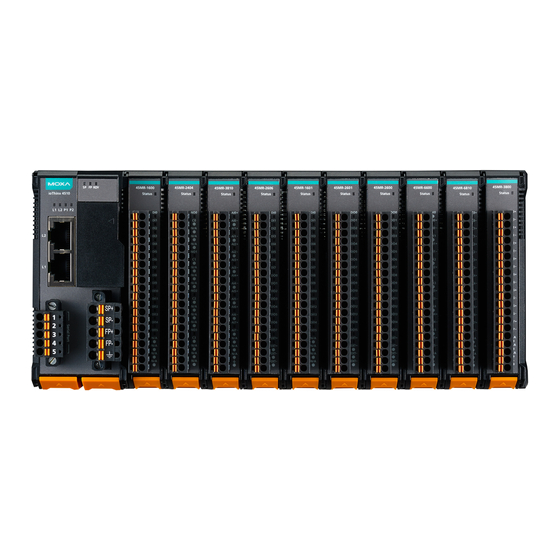
Page 12: Appearance
4510 Series Product Overview Appearance Front View Physical Dimensions Unit: mm (in) -
Page 13: Led Indicators
4510 Series Product Overview LED Indicators Labeling Indication LED Qty LED Color LED Action System On: power on Green Power Off: power off On: power on Field Power Green Off: power off Green: system ready Green slow blinking: booting up... -
Page 14: Hardware Installation
Hardware Installation In this chapter, we describe how to install the ioThinx 4510 Series devices. The following topics are covered in this chapter: Wiring System and Field Power System Power Field Power Wiring Ethernet Ports Wiring Serial Port(s) ... -
Page 15: Wiring System And Field Power
4510 Series Hardware Installation Wiring System and Field Power Wire range: 12 to 26 AWG (Ferrule diameter: 2.0 to 0.4 mm) Wire strip length: 10 mm Unit: mm (in.) The device requires two sets of power inputs. One is for the system (internal logic circuit), and the other is for field I/O circuits. -
Page 16: Field Power
4510 Series Hardware Installation • 10 x 45MR-1600 (59.4 mA) = 594 mA • 5 x 45MR-3810 (187 mA) = 935 mA The total system current is 1.594 A, which is greater than 1 A. Therefore, an additional 45MR-7210 is needed. -
Page 17: Wiring Serial Port(S)
4510 Series Hardware Installation Wiring Serial Port(s) Wire range: 16 to 28 AWG (Ferrule diameter: 1.2 to 0.3 mm) Wire strip length: 9.0 mm Unit: mm (in.) RS-232 RS-422 RS-485 (P1/P2) TXD+ DATA1+ TXD- DATA1- RXD+ DATA2+ RXD- DATA2- NOTE Connect the signal common pin (e.g. -
Page 18: Connecting The Field Power Ground
4510 Series Hardware Installation CAUTION For surge protection, connect the DIN rail to earth ground. Connecting the Field Power Ground Connect the field power ground pin ( ) to your field power ground. CAUTION Be sure to note the maximum possible current for each power wire and common wire. Observe all electrical codes dictating the maximum current allowable for each wire size. -
Page 19: Mounting The Unit
4510 Series Hardware Installation Mounting the Unit In this section, we describe how to mount the device on a DIN rail and how to unmount the device from a DIN rail. DANGER Never install the device while the power source is switched on. -
Page 20: Removing The Unit From A Din Rail
4510 Series Hardware Installation Removing the Unit from a DIN Rail Take the following steps to remove the unit from a DIN rail. Step 1: Use your finger to pull the release tab on the lower part of the module. -
Page 21: Installing Covers On The Device And The Right-Most I/O Module
4510 Series Hardware Installation Installing Covers on the Device and the Right-Most I/O Module Insert the covers on the left side of the device and on the right side of the I/O module that is installed furthest to the right. Make sure the covers cover the internal bus of the module. -
Page 22: Horizontal Installation
4510 Series Hardware Installation Horizontal Installation Before installing the device, ensure there is enough space around the device so that it can dissipate heat. In order to ensure the device works properly, we suggest reserving the space shown in the figure below. -
Page 23: Software Tools
Software Tools In this chapter, we introduce which software tools can be used with this device. The following topics are covered in this chapter: Preparing Software Tools Connecting Web Console Preparing IOxpress Utility Preparing Moxa CLI Configuration Tool ... -
Page 24: Preparing Software Tools
Refer to the Mass-deploying the Settings section for detailed instructions. NOTE The ioThinx 4510 Series is only compatible with IOxpress v2.2 or later. Preparing Moxa CLI Configuration Tool Moxa CLI Configuration Tool (MCC_Tool) can be downloaded from the Moxa website at www.moxa.com. -
Page 25: Web Console
4510 Series Software Tools Web Console The Web Console is the main software tool to configure, monitor, and operate a device. If mass deploying to multiple devices is required, use IOxpress utility instead. The Web Console is divided into three regions: 1. -
Page 26: Dashboard
4510 Series Software Tools Dashboard The dashboard provides information about the system, modules, I/Os, and the connection status. It also allows you to exit the safe mode status or to change the I/O status. System Information The one page system information provides detailed information for this device. For information regarding modules and I/Os, click Module &... - Page 27 4510 Series Software Tools Locate: Identify the physical location of the module and the module’s status LED will blink green. DI Channel (DI Mode): It shows the status of this channel. No operation is allowed. DI Channel (Counter Mode): It shows the status of this channel. Type a value between 0 and 4294967295, and then click SET to set the current counter value.
-
Page 28: System
4510 Series Software Tools RTD Channel: It shows the status of this channel. Click RESET to reset the minimum and maximum values. Apply the reference temperature value in the calibration field and click SET to start the RTD sensor calibration;... - Page 29 4510 Series Software Tools Device Settings Device Name: Set the name of this device (max length = 16, '.' is not allowed). Language: Select the language of the web console. Time Settings System Date & Time: Select the date for the device. Click Set Time to set the time of the device.
- Page 30 4510 Series Software Tools Watchdog Safe Mode on Service: Select the service that you want to link the watchdog to in order to keep monitoring the connection status (option: Modbus TCP Slave). Communication Watchdog for Safe Mode: The timeout value when the master of Safe Mode on Service is disconnected (unit: sec(s), 0 to 65535, 0 is disable).
- Page 31 4510 Series Software Tools Configuration Select File: Click Browse to select a configuration file to update the device. Update network settings (IP, Gateway, etc.): Click the checkbox if the network settings need to be updated. Update to Device: Click Update to update the firmware to the device.
-
Page 32: Security
4510 Series Software Tools NOTE Do not disconnect the power or network cable during the update process. NOTE This device supports firmware automatic recovery function. If the firmware in the device is corrupted, the system will load the backup firmware automatically to overwrite the corrupted one. When the system is in recovery mode, the RDY LED will slowly blink red. - Page 33 4510 Series Software Tools NOTE If all services are disabled, this device will no longer be accessible, and you will need to load the factory default configurations to access the device. NOTE For security reasons, we suggest disabling those services that your application will not use.
- Page 34 4510 Series Software Tools NOTE Change the default password in order to enhance security when you first login. INFORMATION The default username is admin, and the default password is moxa. Account Settings Idle Timeout: The timeout value when the user account is idle (unit: min(s), 0 to 1440 mins, default: 5 mins) Note: 0 for disabled.
-
Page 35: Network
4510 Series Software Tools Access Control Use IP Address/Netmask combinations to control which devices can access the device. Certificate Settings The ioThinx 4510 will generate a self-signed certificate based on the IP address. Users can download the certificate by clicking the Export button, and then import the certificate through the browser to enhance security. -
Page 36: Module
4510 Series Software Tools LAN Settings IP Configuration: Configure the following settings if Static IP is selected. If DHCP is selected, the following settings are not allowed (option: Static IP or DHCP). IP Address: Set the IP address of the device (0 to 255). - Page 37 4510 Series Software Tools Edit: Click this button to enter edit mode. Save Settings: This button only appears in edit mode. Click this button to finish module settings and exit edit mode. Cancel: This button only appears in edit mode. Click this button to cancel module settings and exit edit mode.
-
Page 38: I/O
4510 Series Software Tools The drag icon allows you to drag the configured module and drop it to the position you need. NOTE The detected module should match the configured module. Otherwise, the Web Console will not allow you to configure other settings. - Page 39 4510 Series Software Tools Digital Input Channel Settings Channel Mode Drop-Down List: It lists all of the channel modes, which can be operated by this channel. Select DI or Counter mode for each channel (option: DI or Counter). Channel Name: The channel name is used for representing this channel (max. length = 16, “.” character is not allowed).
- Page 40 4510 Series Software Tools NOTE Not all DI channels support counter mode. Refer to the ioThinx 4500 Series (45MR) Modules datasheet for detailed specifications. Digital Output Channel Settings Channel Mode Drop-Down List: It lists all of the channel modes, which can be operated by this channel.
- Page 41 4510 Series Software Tools NOTE Not all DO channels support pulse mode. Refer to the ioThinx 4500 Series (45MR) Modules datasheet for detailed specifications. Relay Channel Settings Channel Name: The channel name is used for representing this channel (max. length = 16, “.” character is not allowed).
- Page 42 4510 Series Software Tools Disable Mode The AI channel can be disabled. It only allows you to disable channels one-by-one. When a channel has been disabled, the sample rate of the remaining channels will be increased automatically. 0-20 mA/4-20 mA burnout/4-20 mA/0-10 V/±10 V Mode Burnout Value (only for 4-20 mA burnout mode): The 4–20 mA burnout mode is shown in the diagram...
- Page 43 4510 Series Software Tools 1st Point Measured Value: The 1 point value in the range of channel mode to be scaled to the 1st Point Scaled Value (unit: mA, 4.000 to 20.000). 2nd Point Measured Value: The 2 point value in the range of channel mode to be scaled to the 2nd Point Scaled Value (unit: mA, 4.000 to 20.000).
- Page 44 4510 Series Software Tools Disable Mode Disable the AO channel. Channels must be disabled one-by-one. 0-10 V/0-20 mA/4-20 mA Mode 1st Point Output Value: The 1 point value in the range of channel mode to be scaled to the 1st Point Scaled Value (range: 0-20 mA mode: 0.000 to 20.000, 4-20 mA mode: 4.000 to 20.000, 0-10V mode:...
- Page 45 4510 Series Software Tools RTD Channel Settings Sensor Type Drop-Down List: It lists all of the sensor types, which can be connected to this channel. Select the sensor type for each channel (option: PT50, PT100, PT200, PT500, PT1000, 310 ohms, 620 ohms, 1250 ohms, 2200 ohms, JPT100, JPT200, JPT500, JPT1000, NI100, NI200, NI500, NI1000, NI120, or Disable).
- Page 46 4510 Series Software Tools Channel Name: The channel name is used for representing this channel (max. length = 16, “.” character is not allowed). Point Measured Value: The 1 point value in the range of channel mode to be scaled to the 1st Point Scaled Value (acceptable input value depends on the type of sensor).
- Page 47 4510 Series Software Tools Disable Mode The TC channel can be disabled. You may only disable channels one-by-one. When a channel has been disabled, the sample rate of the remaining channels will be increased automatically. Channel Name: The channel name is used for representing this channel (max. length = 16, “.” character is not allowed).
-
Page 48: Serial Port
4510 Series Software Tools System Power (SP) channel Setting Channel Name: The channel name is used for representing this channel (max. length = 16, “.” character is not allowed). System Power Lower Limit Value: When the system power voltage drops below the limit, the system power alarm will be triggered. - Page 49 4510 Series Software Tools Port 1/Port 2 Click the tab to configure the settings of Port 1 or Port 2. NOTE The Port 2 tab is only available when the Mode of the Port 1 is RS-485 2-Wire. Mode: The standard of the serial device connected to this port (option: RS-232, RS-422, or RS-485 2- Wire).
- Page 50 4510 Series Software Tools Device Drop-Down List: It shows the device name of the Modbus RTU devices. Select one of the devices to configure its settings. The green icon shows that data collection from the device is enabled. Enable Device: Click the checkbox to enable data collection from the device. The icon beside the Modbus device in the Device Drop-Down List will change from red to green after being enabled.
- Page 51 4510 Series Software Tools After creating a new profile, configure the settings of the profile. Profile Name: Name the profile of the Modbus device (max. length = 16; “.” character is not allowed). Point Type: Set the corresponding Modbus point type setting (option: 01: Coil Status (R/W), 02: Input Status (R), 03: Holding Register (R/W), or 04: Input Register (R)) Start Address: Define the start address of this Modbus tag (0 to 65535).
-
Page 52: Internal Register
4510 Series Software Tools Internal Register This section introduces functions of Internal Register settings. The Internal Registers, which store the data retrieved from the Modbus/RTU master, can be mapped to the supported northbound protocols, such as Modbus/TCP, RESTful API, and MQTT. -
Page 53: Protocol
4510 Series Software Tools IR Information: The IR status window will pop-up after you click one of the IR blocks. The name is used for representing this internal register (max. length = 16, “.” character is not allowed). Protocol This section introduces the protocol settings functions. - Page 54 4510 Series Software Tools Reload Configuration: Click this button to reload the configuration settings of all Modbus registers. Filter: Type characters into the textbox to filter the items in the Modbus Table. Point Type Category: Click 01: Coil Status (R/W), 02: Input Status (R), 03: Holding Register (R/W), or 04: Input Register (R) tab to see the registers under the specific point type.
- Page 55 4510 Series Software Tools Start Address Textbox: Change the value of the Start Address in the textbox (0 to 65535 or leave it blank). When there is no value in the textbox, it will be displayed in light yellow. When it conflicts with another register, it will be displayed in red.
- Page 56 4510 Series Software Tools SNMP In the SNMP page, settings are divided into three tabs: SNMP, SNMP Trap/Inform, and Event Settings. SNMP Settings Version: Select one of the SNMP version options (option: v1 and v2c, v3 only, or v1 and v2c and v3), through which the SNMP Manager can access the SNMP agent of the device.
- Page 57 4510 Series Software Tools SNMPv1, SNMPv2c Settings Read Community: Type the community string matching for read authentication (max length = 30, default = "public"). Write Community: Type the community string matching for write authentication (max length = 30, default = "private").
- Page 58 4510 Series Software Tools SNMPv3 Settings – Read/Write Username: Type the username for the SNMP v3 settings (min. length = 1; max length = 30; A to Z, a to z, 0 to 9, symbols, spaces and .()[]{}/\'"@;: symbols are not allowed, default = "v3rw").
- Page 59 4510 Series Software Tools Trap Community: Type the community string matching for read authentication (max length = 30, default = "public"). Username: Type the username for the SNMP v3 settings (min. length = 1; max length = 30; A to Z, a to z, 0 to 9, symbols, spaces and .()[]{}/\'"@;: symbols are not allowed, default = "v3").
- Page 60 4510 Series Software Tools Trigger: Select the event trigger type. For Digital Input, there are three options, On Change, ON to OFF, and OFF to ON. For Analog Input, the two trigger options are Greater and Less. Value: Type the threshold value of the trigger. This is only used for Analog Input events.
- Page 61 4510 Series Software Tools MQTT The ioThinx 4510 supports MQTT version 3.1.1. In this section we introduce the MQTT settings. The MQTT configuration page has two channels: Connection Settings and Topic Settings. Connection Settings Broker IP Specifies the broker IP name.
- Page 62 4510 Series Software Tools Last Will Topic: The “topic” of the last will message that will be sent to the broker. This item is not configurable. Last Will Message: The message that will be sent to the broker when the connection between the ioThinx 4510 and the broker is disconnected.
- Page 63 4510 Series Software Tools • aiValueScaled • aoStatus • aoValueScaled • rtdStatus • rtdValueScaled • tcStatus • tcValueScaled Enable/Disable: Filter out the enabled or disabled topic. Textbox: Type in the topic that you would like to filter. Batch Edit: The ioThinx 4510 supports the Enable/Disable/QoS/Retain/Trigger function for batch editing.
-
Page 64: Quick Start Guide
Quick Start Guide The following topics are covered in this chapter: Configuring the Unit Login to the Unit Configuring Module Settings Changing Device Name Changing Username & Password Configuring Service Settings Configuring Account Settings ... -
Page 65: Configuring The Unit
4510 Series Quick Start Guide Configuring the Unit This section explains how to configure this device through the Web Console from the beginning. If you require additional information, please refer to Preparing Software Tools before reading this section. Login to the Unit Follow the steps to log in to the unit. - Page 66 4510 Series Quick Start Guide If you see the module settings page as opposed to the dashboard, click Edit to enter the edit mode and start editing the module settings. In edit mode, if any detected module and configured module do not match, the configured module will be highlighted as shown below.
-
Page 67: Changing Device Name
4510 Series Quick Start Guide Changing Device Name Set the name of this device through System Device Settings. We recommend choosing a unique name for the device in order to easily differentiate it from other devices. Changing Username & Password In order to have higher levels of security, we recommend changing the username and password after your first log in. -
Page 68: Configuring Service Settings
For account settings, the user can modify the parameters and define the login failure message and system usage notifications. If the user wants to know the access history, the ioThinx 4510 Series supports access log export, which can store up to 1000 records. -
Page 69: Configuring Network Settings
4510 Series Quick Start Guide Configuring Network Settings Click Network on the menu panel to enter the network settings page as shown below. The ioThinx 4510 Series supports Ethernet daisy-chain topology with one MAC address. For this LAN port, it supports static IP and DHCP mode. -
Page 70: Configuring I/O Settings
4510 Series Quick Start Guide Configuring I/O Settings Click I/O on the menu panel to enter the I/O settings page. For more detailed information, please refer to the I/O Settings chapter. Configuring Modbus Address Settings Click Modbus on the menu panel to enter the Modbus TCP Slave setting page. On this page, users can see all of the Modbus TCP addresses categorized by coil status, input status, holding register, and input register. -
Page 71: Configuring Snmp Settings
Click SNMP on the menu panel to enter the SNMP settings page as shown below. The ioThinx 4510 Series supports SNMP, SNMP Trap, and SNMP Inform. After configuring these settings, please download the mib file from Moxa’s website. For detailed information on the structure of the mib file, please refer to the SNMP chapter. -
Page 72: Mass-Deploying The Settings
Min. 512 MB, 1024 MB is recommended Network 10/100 Ethernet NOTE The ioThinx 4510 Series is only compatible with IOxpress v2.4 or later. INFORMATION To get the latest version of IOxpress, please download it from www.moxa.com Users can change IP address, update configurations, change the device name, and set the date and time to multiple units by IOxpress. - Page 73 4510 Series Quick Start Guide Step 3: Open IOxpress, go to the Device Library and click Device Search in the menu. 5-10...
- Page 74 4510 Series Quick Start Guide Step 4: In the Search for Devices window, choose the product series you would like to search for in the By Product Series dropdown menu, and then click Submit. IOxpress will start to search the devices and list them in the table.
-
Page 75: Updating Configuration To Multiple Units
4510 Series Quick Start Guide Updating Configuration to Multiple Units IOxpress supports updating configuration of multiple units. Follow the steps to complete this task. Step 1: Export the configuration file of a device through the Web Console. Refer to Backing up Configuration Files for more details. -
Page 76: Setting Date And Time To Multiple Units
4510 Series Quick Start Guide Setting Date and Time to Multiple Units The IOxpress supports setting the date and time of multiple units. Follow these steps to complete this task. Step 1: Select Set Device Date & Time in the dropdown button Step 2: Select either Sync with PC or Manual Setting. -
Page 77: Changing Ip Addresses To Multiple Devices
4510 Series Quick Start Guide Changing IP Addresses to Multiple Devices IOxpress supports changing IP addresses for multiple devices: Step 1: Select Change IP Address in the dropdown button list. Step 2: Select the device(s), change the IP address, type the Username and Password, and then click Submit. -
Page 78: Retrieving The System Log From Multiple Devices
4510 Series Quick Start Guide Step 2: Select the device(s), change the device name, type the Username and Password, and then click Submit. IOxpress will start to execute the task on the selected devices. A indicating success message will appear in the Result column if the process was completed successfully. -
Page 79: Getting A Self-Signed Certificate From Multiple Devices
To monitor and operate the device, go to the Dashboard of the Web Console. INFORMATION The ioThinx 4510 Series supports three different user profiles (Administrator, Operator, and User). Refer to User Settings for the permission information of each profile. NOTE The HTTPS web service can only be used for configuration purposes;... -
Page 80: Monitoring Module & I/O Status
4510 Series Quick Start Guide Monitoring Module & I/O Status Under the Dashboard of the Web Console, click Module & I/O to go to the module and I/O status web page. The upper side of this page shows the module status, including Slot position, module Status, Firmware Version, Module Name, Model Name, and Serial Number. -
Page 81: Exiting Safe Mode Status
Modbus connection has reconnected. Maintaining the Unit This section introduces the maintenance functions of the ioThinx 4510 Series. Backing up Configuration Files This device can only be configured through the web console. After configuration, the configuration file can be retrieved from the device to perform backup and mass deployment. -
Page 82: Updating The Firmware
4510 Series Quick Start Guide Updating the Firmware Follow the steps to update the firmware to the device. Step 1: Go to the configuration page via Menu System Firmware Step 2: Click the Browse button to select a firmware file to update... -
Page 83: Restarting The Unit
4510 Series Quick Start Guide Restarting the Unit This device will restart automatically after the firmware and configurations have been updated. The user can also restart the device manually. Step 1: Click Save & Restart on the right upper corner of the page. - Page 84 4510 Series Quick Start Guide 2. Follow the steps to load the factory default settings from IOxpress. Step 1: Select Load Factory Default from the dropdown menu. Step 2: Select the device(s), type the Username and Password, and then click Submit. IOxpress will start to perform the task on the selected devices.
-
Page 85: Tutorials
Type page 1 content here. The following topics are covered in this chapter: How to Use Modbus TCP to Connect to the ioThinx 4510 Series Using Modbus TCP via Modbus Poll How to Use RESTful API to Connect to the ioThinx 4510 Series ... -
Page 86: How To Use Modbus Tcp To Connect To The Iothinx 4510 Series
4510 Series Tutorials How to Use Modbus TCP to Connect to the ioThinx 4510 Series Using Modbus TCP via Modbus Poll Introduction to Modbus Poll Please refer to the following web page for information about Modbus Poll: https://www.modbustools.com/modbus_poll.html Modbus Poll Moxa ioThinx 4510 IP address: 192.168.127.200... - Page 87 4510 Series Tutorials 3. Click Save & Restart in the top right of the page and then click Save and Restart in the center of the page. Set Up a Connection on Modbus Poll 1. Select Connect on Modbus Poll’s Connection panel.
- Page 88 4510 Series Tutorials Write Single Coil: Use Modbus Poll to turn on an ioThinx 4510 DO channel 1. Select Read/Write Definition under the Setup menu. 2. Select the function code 05 Write Single Coil and then enter 0, the start Address of the DO channel.
- Page 89 4510 Series Tutorials 2. Type the text “doStatus” in the filter to find the Start Address of the DO channel. NOTE You can also manually modify the addresses if needed. To do so, click Save & Restart in the top right of the page after changing the Start Address.
- Page 90 4510 Series Tutorials Read Coils: Use Modbus Poll to read the ioThinx 4510 DO channel status. 1. Select Read/Write Definition in the Setup panel. 2. Select the function code 01 Read Coils and enter 0, the start Address of the DO channel.
-
Page 91: How To Use Restful Api To Connect To The Iothinx 4510 Series
4510 Series Tutorials How to Use RESTful API to Connect to the ioThinx 4510 Series Using RESTful API via Postman Introduction to Postman For information about Postman, please refer to the following web page: https://www.getpostman.com/. Step-by-step procedures on how to use Postman are described below. - Page 92 4510 Series Tutorials 3. Click Save & Restart in the top right corner of the page and then click Save and Restart in the center of the page. Configuring Postman 1. Open Postman and create a new Request (named GET example).
-
Page 93: Send A Get Request And A Put Request
4510 Series Tutorials 6. Create the following content in the Headers of the GET example tab and PUT example tab. Content-Type: application/json Accept: vdn.dac.v2 Send a GET request and a PUT request RESTful API List Rules You can check the RESTful API list here: RESTful API Rules. - Page 94 4510 Series Tutorials 3. Change the DO-00 channel name to Light. Send a GET request 1. Enter the request URL based on the IP address, file type, and API map. For this example, the request URL should be written as: 192.168.127.254/api/io/di/GET_Demo@Button/diStatus...
-
Page 95: How To Use Mqtt To Connect To The Iothinx 4510 Series
4510 Series Tutorials 4. Click Send. The DO-00 channel should respond by turning the light on. How to Use MQTT to Connect to the ioThinx 4510 Series Broker Settings on the Computer Introduction to Mosquitto For information about Eclipse Mosquitto, please refer to the following web page: https://mosquitto.org/. - Page 96 4510 Series Tutorials 2. Click Security in the left menu. Select Service Settings at the top of the page and then select MQTT Client. Connection and Topic Settings 1. Select MQTT in the left menu and then set the Broker IP (your host’s IP) under Connection Settings.
- Page 97 4510 Series Tutorials NOTE The content of the Topic is based on Device Name, Module name, and I/O channel. You can change these values in Device Settings, Module Settings, and I/O Settings. In this demonstration, we changed our Topic #1 (DI-00 and DO-00) as below:...
-
Page 98: Publisher And Subscriber Settings
4510 Series Tutorials 3. Click Save & Restart in the upper-right corner, and then click Save and Restart in the center of the page. Publisher and Subscriber Settings Introduction to MQTTlens MQTTLens is a chrome application that supports MQTT communications. MQTTLens can be used to simulate communicating with the ioThinx 4510 via MQTT. - Page 99 4510 Series Tutorials Scenario 1: Publish DI status to MQTTlens • Publisher: ioThinx 4510 • Subscriber: MQTTlens 1. Copy the topic from the ioThinx 4510 MQTT publisher tab. Paste the topic into the subscribe column of the MQTTlens, and then click subscribe.
-
Page 100: How To Connect Iothinx 4510 To An Mqtt Broker Over Tls
4510 Series Tutorials How to Connect ioThinx 4510 to an MQTT Broker over TLS When using MQTT over TLS, the broker should support the following encryption method, which is supported by ioThinx 4510. • MBEDTLS_TLS_ECDHE_ECDSA_WITH_AES_128_GCM_SHA256 • MBEDTLS_TLS_ECDHE_ECDSA_WITH_AES_128_CBC_SHA256 Broker Settings on the Computer Moxa ioThinx 4510 IP address: 192.168.127.200... - Page 101 4510 Series Tutorials 3. Select Path and click edit in the user variables section. 6-17...
- Page 102 4510 Series Tutorials 4. Create a new path for OpenSSL. Generate Certificate 1. Run CMD (Command Prompt) as administrator 2. Generate certificate for the broker by entering below commands in cmd: openssl ecparam -name prime256v1 -genkey -noout -out key.pem ...
- Page 103 4510 Series Tutorials The files shown below will be generated. Put the files in the mosquitto folder. Modify mosquitto.conf 1. Open mosquitto.conf in the mosquitto folder. 2. Type in below certificate information in the #Certificate based SSL/TLS support section.
-
Page 104: Client (Publisher) Setting
4510 Series Tutorials Client (publisher) setting Use ioThinx 4510 to publish a message to the broker. 1. Set the Broker IP (your computer’s IP) under Connection Settings. Enable TLS, the default Broker Port is 8883. 2. Click Publisher and enable Topic#1 (DI-00), then click Save and Restart. -
Page 105: Appendix
Appendix The following topics are covered in this appendix: Network Port Usage Modbus/TCP Slave Rules Supported Function Code Exception Code System Registers 45MR-1600 (-T), 16 DIs Registers 45MR-1601 (-T), 16 DIs Registers 45MR-2404 (-T), 4 Relays Registers ... -
Page 106: Network Port Usage
4510 Series Appendix Network Port Usage Service Type TCP/UDP Port Default DHCP Disabled Web Server Enabled RESTful API Disabled SNMP Agent Disabled HTTPs Disabled Modbus/TCP Slave Enabled Auto Search 4800 Enabled IOxpress/CLI 10124 Enabled Modbus/TCP Slave Rules Supported Function Code... -
Page 107: 45Mr-1600 (-T), 16 Dis Registers
4510 Series Appendix 04: INPUT REGISTER Parameter Description Length Type modbusRtuMasterDeviceStatus Modbus/RTU Master - device status WORD modbusRtuMasterprofileErrorCode Modbus/RTU Master - profile error code WORD deviceName device name BYTE deviceDate device date DWORD e.g. 2016/06/28 -> 20160628 deviceTime device local time DWORD e.g. -
Page 108: 45Mr-1601 (-T), 16 Dis Registers
4510 Series Appendix 45MR-1601 (-T), 16 DIs Registers 01: COIL STATUS Parameter Description Length Type diCounterStatus DI - Counter mode - status (0: Pause, 1: Run) BOOL diCounterOverflowFlagClear DI - Counter mode - clear overflow flag (1: Clear) BOOL... -
Page 109: 45Mr-2600 (-T), 16 Dos Registers
4510 Series Appendix 45MR-2600 (-T), 16 DOs Registers 01: COIL STATUS Parameter Description Length Type doStatus DO - status (0: OFF, 1: ON) BOOL doPulseStatus DO - Pulse mode - status (0: Stop, 1: Start) BOOL 02: INPUT STATUS? -
Page 110: 45Mr-2606 (-T), 8 Dis, 8 Dos Registers
4510 Series Appendix 45MR-2606 (-T), 8 DIs, 8 DOs Registers 01: COIL STATUS Parameter Description Length Type doStatus DO - status (0: OFF, 1: ON) BOOL diCounterStatus DI - Counter mode - status (0: Pause, 1: Run) BOOL diCounterOverflowFlagClear... -
Page 111: 45Mr-3800 (-T), 8 Ais Registers
4510 Series Appendix 45MR-3800 (-T), 8 AIs Registers 01: COIL STATUS Parameter Description Length Type aiResetMinValue AI - reset minimum value (1: Reset) BOOL aiResetMaxValue AI - reset maximum value (1: Reset) BOOL 03: HOLDING REGISTER Parameter Description Length... -
Page 112: 45Mr-4420 (-T), 4 Aos Registers
4510 Series Appendix 45MR-4420 (-T), 4 AOs Registers 03: HOLDING REGISTER Parameter Description Length Type aoValueRaw AO - raw value WORD aoValueScaled AO - scaled value REAL 04: INPUT REGISTER Parameter Description Length Type aoMode AO - mode (0: disable, 1: 0-10 V, 2: 0-20 mA, WORD 3: 4-20 mA, 4: ±10 V) -
Page 113: 45Mr-6810 (-T), 8 Tcs Registers
4510 Series Appendix 45MR-6810 (-T), 8 TCs Registers 01: COIL STATUS Parameter Description Length Type tcResetMinValue TC - reset minimum value (1: Reset) BOOL tcResetMaxValue TC - reset maximum value (1: Reset) BOOL 03: HOLDING REGISTER Parameter Description Length... -
Page 114: Restful Api Rules
4510 Series Appendix RESTful API Rules Supported Request Method Request Description The GET method is used to retrieve information from the given server using a given URI. Requests using GET should only retrieve data and should have no other effect on the data. - Page 115 4510 Series Appendix RESTful API Description Access Format /api/io/sp/{ioName}/spUpperLimitValue SP - system power upper Float limit value /api/io/fp/{ioName}/fpStatus FP - Field Power Status /api/io/di/{ioName}/diMode DI - mode (0: DI, 1: 0 or 1 Counter) /api/io/di/{ioName}/diStatus DI - DI mode - status (0:...
-
Page 116: Exception Code
4510 Series Appendix RESTful API Description Access Format /api/io/ao/{ioName}/aoMode AO - mode (0: disable, 1: 0, 1, 2, 3, 4 0-10 V, 2: 0-20mA, 3: 4- 20 mA, 4: +/-10V) /api/io/ao/{ioName}/aoValueRaw AO - raw value 0 to 65535 /api/io/ao/{ioName}/aoValueScaled... -
Page 117: Mqtt Rules
4510 Series Appendix HTTP Status Code Moxa Status Code/Description User message Bad Request InvalidNodeValue One of the node value is invalid. Bad Request WrongChannelOrder The I/O channels are disordered. Bad Request MissingRequiredChannel A required channel index was not specified in the request body. - Page 118 4510 Series Appendix Topic Description Category Trigger {deviceName}/read/{ioName}/diCounterValue DI - Counter mode - value Interval value {deviceName}/read/{ioName}/diCounterOverflow DI - Counter mode - attribute Interval Flag overflow flag (0: Normal, 1: Overflow) {deviceName}/read/{ioName}/diCounterOverflow DI - Counter mode - attribute Interval...
- Page 119 4510 Series Appendix Topic Description Category Trigger {deviceName}/read/{ioName}/aiValueScaledMax AI - maximum scaled attribute Interval value {deviceName}/read/{ioName}/aoMode AO - mode (0: attribute Interval Disable, 1: 0-10 V, 2: 0-20mA, 3: 4-20 mA) {deviceName}/read/{ioName}/aoValueRaw AO - raw value attribute Interval {deviceName}/read/{ioName}/aoValueScaled...
-
Page 120: Subscribe Topic
4510 Series Appendix Topic Description Category Trigger {deviceName}/write/{ioName}/tcResetMinValue TC - reset minimum attribute Interval value (1: RESET) {deviceName}/write/{ioName}/tcResetMaxValue TC - reset maximum attribute value (1: RESET) Subscribe Topic Topic Description Template Category {deviceName}/write/{ioName}/birValue BIR - value 0 to 1... -
Page 121: Troubleshooting
4510 Series Appendix Troubleshooting This section provides troubleshooting instructions for this device. Forgot username & password If you forget your username and password, use a pointed object such as a straightened paper clip to hold down the Reset Button for 10 seconds. This will restart the unit and reset all settings on the device, including the username and password. -
Page 122: Failed To Update Firmware
4510 Series Appendix Step 2: In the Search for Devices window, choose the product series you would like to search in the By Product Series dropdown menu, and then click the Submit button. IOxpress will start to search the devices and list them in the table. -
Page 123: Failed To Access The Unit Through Ip Address & Ioxpress
4510 Series Appendix Failed to access the unit through IP address & IOxpress Incorrect network configurations can result in the user not being able to access the unit. Check if the device and PC are in the same subnet by following the procedure below. -
Page 124: Import Self-Signed Certificate
4510 Series Appendix Import Self-Signed Certificate When using web service via https, you must import the self-signed certificate before using the web service via https, or the browser may block the connection. Take the following steps to import the self-signed certificate, which was generated by the ioThinx 4510, into the browser. - Page 125 4510 Series Appendix 4. Click the Trusted Root Certification Authorities tab and then click Import 5. Choose the certificate exported by the ioThinx 4510 and then click Next. A-21...
- Page 126 4510 Series Appendix 6. Click Next until you see the following page, and then click Finish to complete the certificate import. 7. When the security warning message pops up, click Yes to complete the certificate installation. A-22...
- Page 127 4510 Series Appendix 8. Open the browser and open the ioThinx 4510’s web console. You should see the lock icon to the left of the web address. A-23...
Need help?
Do you have a question about the ioThinx 4510 Series and is the answer not in the manual?
Questions and answers