Moxa Technologies ioLogik E1210 User Manual
Iologik e1200 series
Hide thumbs
Also See for ioLogik E1210:
- User manual (75 pages) ,
- Manual (7 pages) ,
- Quick installation manual (2 pages)

Related Manuals for Moxa Technologies ioLogik E1210


Summary of Contents for Moxa Technologies ioLogik E1210
- Page 1 ioLogik E1200 Series User’s Manual Edition 12.0, October 2016 www.moxa.com/product © 2016 Moxa Inc. All rights reserved.
- Page 2 ioLogik E1200 Series User’s Manual The software described in this manual is furnished under a license agreement and may be used only in accordance with the terms of that agreement. Copyright Notice © 2016 Moxa Inc. All rights reserved. Trademarks The MOXA logo is a registered trademark of Moxa Inc.
-
Page 3: Table Of Contents
Product Features ..........................1-2 Inside the Box ............................ 1-2 Product Model Information ........................1-3 Product Specifications ......................... 1-4 Common Specifications ........................ 1-4 ioLogik E1210 ..........................1-5 ioLogik E1211 ..........................1-5 ioLogik E1212 ..........................1-6 ioLogik E1213 ..........................1-7 ioLogik E1214 ..........................1-8 ioLogik E1240 .......................... - Page 4 Establishing communication between the ioLogik E1200 device and the Allen-Bradley PLC ......6-6 Modbus/TCP Default Address Mappings .................... A-1 ioLogik E1210 Modbus Address and Register Map ................... A-2 ioLogik E1211 Modbus Address and Register Map ................... A-3 ioLogik E1212 Modbus Address and Register Map ................... A-5 ioLogik E1213 Modbus Address and Register Map ...................
-
Page 5: Introduction
The following topics are covered in this chapter: Product Features Inside the Box Product Model Information Product Specifications Common Specifications ioLogik E1210 ioLogik E1211 ioLogik E1212 ioLogik E1213 ioLogik E1214 ioLogik E1240 ... -
Page 6: Product Features
ioLogik E1200 Series Introduction Product Features • Active communication with patented MX-AOPC UA Server • 2-port Ethernet switch for daisy-chain topologies • Easy mass deployment and configuration with ioSearch™utility • User-friendly configuration via web browser • Save time and wiring costs with peer-to-peer communication •... -
Page 7: Product Model Information
E1200 Series Introduction Product Model Information Model Description ioLogik E1210 Remote Ethernet I/O with 2-port Ethernet switch and 16 DIs ioLogik E1211 Remote Ethernet I/O with 2-port Ethernet switch and 16 DOs ioLogik E1212 Remote Ethernet I/O with 2-port Ethernet switch, 8 DIs, and 8 DIOs... -
Page 8: Product Specifications
ioLogik E1200 Series Introduction Product Specifications Common Specifications Ethernet: 2 switched 10/100 Mbps RJ45 ports Protection: 1.5 kV magnetic isolation Protocols: Modbus/TCP (Slave), EtherNet/IP, SNMPv1/v2c, RESTful API, TCP/IP, UDP, DHCP, BOOTP, HTTP Physical Characteristics Wiring: I/O cable max. 14 AWG Dimensions: 27.8 x 124 x 84 mm (1.09 x 4.88 x 3.31 in) Weight: Under 200 g (0.44 lb) Mounting: DIN rail or wall... -
Page 9: Iologik E1210
E1200 Series Introduction ioLogik E1210 Inputs and Outputs Digital Inputs: 16 channels Isolation: 3k VDC or 2k Vrms Digital Input Sensor Type: Wet Contact (NPN or PNP), Dry Contact I/O Mode: DI or Event Counter Dry Contact: • On: short to GND •... -
Page 10: Iologik E1212
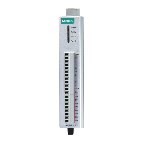
ioLogik E1200 Series Introduction ioLogik E1212 Inputs and Outputs Digital Inputs: 8 channels Configurable DIOs (by jumper): 8 channels Isolation: 3k VDC or 2k Vrms Digital Input Sensor Type: Wet Contact (NPN or PNP), Dry Contact I/O Mode: DI or Event Counter Dry Contact: •... -
Page 11: Iologik E1213
ioLogik E1200 Series Introduction ioLogik E1213 Inputs and Outputs Digital Inputs: 8 channels Digital Outputs: 4 channels Configurable DIOs (by jumper): 4 channels Isolation: 3k VDC or 2k Vrms Digital Input Sensor Type: Wet Contact (NPN or PNP), Dry Contact I/O Mode: DI or Event Counter Dry Contact: •... -
Page 12: Iologik E1214
ioLogik E1200 Series Introduction ioLogik E1214 Inputs and Outputs Digital Inputs: 6 channels Relays: 6 channels Isolation: 3k VDC or 2k Vrms Digital Input Sensor Type: Wet Contact (NPN or PNP), Dry Contact I/O Mode: DI or Event Counter Dry Contact: •... -
Page 13: Iologik E1240
ioLogik E1200 Series Introduction ioLogik E1240 Inputs and Outputs Analog Inputs: 8 channels Isolation: 3k VDC or 2k Vrms Analog Input Type: Differential input Resolution: 16 bits I/O Mode: Voltage / Current (jumper selectable) Input Range: 0 to 10 VDC, 0 to 20 mA, 4 to 20 mA, 4 to 20 mA (burnout detection) Accuracy: ±0.1% FSR @ 25°C ±0.3% FSR @ -10 and 60°C... -
Page 14: Iologik E1242
ioLogik E1200 Series Introduction ioLogik E1242 Inputs and Outputs Digital Inputs: 4 channels Configurable DIOs (by jumper): 4 channels Analog Inputs: 4 channels Isolation: 3k VDC or 2k Vrms Digital Input Sensor Type: Wet Contact (NPN or PNP), Dry Contact I/O Mode: DI or Event Counter Dry Contact: •... -
Page 15: Iologik E1260
ioLogik E1200 Series Introduction ioLogik E1260 Inputs and Outputs RTDs: 6 channels Isolation: 3k VDC or 2k Vrms Sensor Type: • PT50, PT100, PT200, PT500 (-200 to 850°C) • PT1000 (-200 to 350°C) • Resistance of 310, 620, 1250, and 2200 ohms Input Connection: 2- or 3-wire Sampling Rate: •... -
Page 16: Iologik E1262
ioLogik E1200 Series Introduction ioLogik E1262 Inputs and Outputs Thermocouples: 8 channels Isolation: 3k VDC or 2k Vrms Thermocouple Sensor Type: J (0 to 750°C), K (-200 to 1250°C), T (-200 to 350°C), E (-200 to 900°C), R (-50 to 1600°C), S (-50 to 1760°C), B (600 to 1700°C), N (-200 to 1300°C) Millivolt Type: •... -
Page 17: Physical Dimensions
ioLogik E1200 Series Introduction Physical Dimensions 1-13... -
Page 18: Hardware Reference
ioLogik E1200 Series Introduction Hardware Reference Panel Guide NOTE The RESET button restarts the server and resets all settings to factory defaults. Use a pointed object such as a straightened paper clip to hold down the RESET button for 5 seconds. The factory defaults will be loaded once the READY LED turns green again. -
Page 19: I/O Circuit Diagram
ioLogik E1200 Series Introduction I/O Circuit Diagram DI Circuit Sinking DO Circuit 1-15... -
Page 20: Sourcing Do Circuit
ioLogik E1200 Series Introduction Sourcing DO Circuit 1-16... -
Page 21: Dio Circuit
ioLogik E1200 Series Introduction DIO Circuit 1-17... -
Page 22: Relay Circuit
ioLogik E1200 Series Introduction Relay Circuit AI Circuit RTD Circuit 1-18... -
Page 23: Tc Circuit
ioLogik E1200 Series Introduction TC Circuit 1-19... -
Page 24: Initial Setup
Initial Setup This chapter describes how to install the ioLogik E1200. The following topics are covered in this chapter: Hardware Installation Connecting the Power Grounding the ioLogik E1200 DIN Rail, Wall Mounting Connecting to the Network ... -
Page 25: Hardware Installation
ioLogik E1200 Series Initial Setup Hardware Installation Connecting the Power Connect the 12 to 36 VDC power line to the ioLogik E1200’s terminal block on the top panel. If power is properly supplied, the Power LED will glow a solid amber color. ATTENTION Determine the maximum possible current for each power wire and common wire. -
Page 26: Connecting To The Network
ioLogik E1200 Series Initial Setup Connecting to the Network The ioLogik E1200 has two built-in RJ45 Ethernet ports for connecting a standard direct or crossover Ethernet cable to either the host PC or another ioLogik E1200 device. For initial setup of the ioLogik E1200, it is recommended that the ioLogik E1200 be configured using a direct connection to a host computer rather than remotely over the network. - Page 27 ioLogik E1200 Series Initial Setup DIO Mode Configuration Settings DIO mode configuration settings are shown below: The default setting is DO Mode. AI Mode Configuration Settings Analog mode configuration settings are shown below: The default setting is Voltage Mode. EXT Power Configuration Settings (ioLogik E1213 Only) The ioLogik E1213 digital outputs have three possible external (EXT) power configurations.
-
Page 28: I/O Wiring Diagrams
ioLogik E1200 Series Initial Setup I/O Wiring Diagrams A Dry Contact is a contact that does not provide voltage. A Wet Contact is a contact that will provide voltage when closed. ATTENTION Remove the screw on the back panel and open the cover to configure the jumpers. - Page 29 ioLogik E1200 Series Initial Setup NOTE It is recommended to use a contact protection circuit for relay output. A varistor can serve as a contact protection circuit, where the parallel circuit connects to the Load. Load NOTE A “load” in a circuit schematic is a component or portion of the circuit that consumes electric power. For the diagrams shown in this document, “load”...
-
Page 30: Iosearch™ Installation
ioLogik E1200 Series Initial Setup ioSearch™ Installation ioSearch™ is a search utility that helps the user locate ioLogik E1200 devices on the local network. You may download the latest version of ioSearch™ from Moxa’s website. 1. Installing the ioSearch™: Download the ioSearch™ utility from Moxa’s website, double click the installation file, and then follow the installation wizard’s instructions to complete the installation. -
Page 31: Using The Web Console
Using the Web Console The ioLogik E1200’s main configuration and management utility is the built-in web console, which can be used to configure a wide range of options. The following topics are covered in this chapter: Introduction to the Web Console ... -
Page 32: Introduction To The Web Console
ioLogik E1200 Series Using the Web Console Introduction to the Web Console The ioLogik E1200 web console is a browser-based configuration utility. When the ioLogik E1200 is connected to your network, you may enter the server’s IP address in your web browser to access the web console. The left panel is the navigation panel and contains an expandable menu tree for navigating among the various settings and categories. -
Page 33: Overview
ioLogik E1200 Series Using the Web Console Overview The Overview page contains basic information about the ioLogik E1200, including the model name, serial number, firmware version, MAC address, and current IP address. Most importantly, you can see the current I/O status by pressing the F5 key on the computer keyboard to refresh the page. -
Page 34: Network Settings For The Web Console
ioLogik E1200 Series Using the Web Console Network Settings for the Web Console General Settings On the General Settings page, you can assign a server name and location to assist you in differentiating between different ioLogik E1200 units. You may also configure the Modbus/TCP timeout interval or enable the Communication Watchdog function. -
Page 35: User-Defined Modbus Addressing
ioLogik E1200 Series Using the Web Console User-Defined Modbus Addressing The input and output addresses can be configured on this page. Select the Enable Modbus/TCP Slave Protocol checkbox, and then configure the start address of each Modbus function. If you do not want to use the Modbus function, deselect the Enable Modbus/TCP Slave Protocol checkbox. -
Page 36: Aopc Server Settings
ioLogik E1200 Series Using the Web Console AOPC Server Settings Moxa’s MX-AOPC Server™ is a software package operated as an OPC driver of an HMI or SCADA system. It seamlessly connects Moxa’s ioLogik products to a wide variety of SCADA systems, including the most popular: Wonderware, Citect, and iFix. - Page 37 ioLogik E1200 Series Using the Web Console 4. Click the Submit button and then the Save/Restart button on the next page. 5. On the Create AOPC Tag page, click on the Create Tags button to “push” tag configurations to the MX-AOPC UA Server utility.
-
Page 38: I/O Settings
ioLogik E1200 Series Using the Web Console I/O Settings DI Channels The status of each DI (digital input) channel appears on the DI Channel Settings page. You can also configure each channel’s digital input mode and parameters by clicking on the channel. DI channels can operate in DI mode or Event Counter mode. - Page 39 ioLogik E1200 Series Using the Web Console NOTE The Host Connection Watchdog is disabled by default and must be enabled for Safe Status settings to take effect. Save Status On Power Failure: The ioLogik E1200 will automatically save the counter value when there is a power failure if this function selected.
-
Page 40: Do Channels
ioLogik E1200 Series Using the Web Console DO Channels On the I/O Setting: DO (Digital Output) Channels page; you can configure each DO channel by clicking on the channel. DO channels can operate in DO mode when the status is either ON or OFF. If you select Pulse Output mode, you can specify the ON Width and OFF Width to generate a square wave. -
Page 41: Ai Channels
ioLogik E1200 Series Using the Web Console The DO channel’s Alias Name and logic definition can also be configured on this page. You can apply the alias name to all channels by clicking on the Apply to all DO channels box. AI Channels The current status of each AI (analog input) channel can be viewed on the AI Channel Settings page. -
Page 42: Ai Input Range
ioLogik E1200 Series Using the Web Console Click on a specific AI channel to enable or disable it by selecting the Enable AI Channel field. There are two modes available for the AI channels: 1. Voltage Mode (See the Jumper Settings (DIO and AI) in Chapter 2 for more details) 2. - Page 43 ioLogik E1200 Series Using the Web Console AI Input: Current Mode Burn Out mode indicates when the Current AI has burned out. For example, the 4–20 mA Burn Out mode is defined in the following diagram: Users can define Burn Out (BO) values (default = 2 mA) for selected ranges. When input values are in the Burn Out range, raw data will register as 0000h to indicate that the analog input has burned out.
-
Page 44: Ao Channels
ioLogik E1200 Series Using the Web Console Selecting Enable Point-Slope formula on the Auto Scaling Settings page will linearly convert the actual current or voltage value into other user-defined units, such as percentage or ppm (parts per million). NOTE The scaled value’s Modbus address differs from the original value. The slope-intercept function is used to compensate when the measurement requires a slight adjustment. -
Page 45: Rtd Channels
ioLogik E1200 Series Using the Web Console Enabling the Point-Slope Formula function on the Auto Scaling Settings page will linearly convert the actual current or voltage value into other user-defined units, such as percentage or ppm (parts per million). NOTE The scaled value’s Modbus address differs from the original value. - Page 46 ioLogik E1200 Series Using the Web Console The ioLogik E1200 allows you to calibrate the temperature sensors. In each channel configuration section, follow the instructions and click the Calibrate button to start the RTD sensor calibration. Each calibration requires around 30 seconds per channel. The ioLogik E1200 allows you to manually adjust the current temperature reading.
-
Page 47: Tc Channels
ioLogik E1200 Series Using the Web Console TC Channels The current status of each TC (Thermocouple) channel can be viewed on the TC Channel page. Click on a specific channel to enable or disable the TC channel. Select the Enable TC Channel checkbox and then select the sensor type that meets the physical attachment to the ioLogik E1200. -
Page 48: Peer-To-Peer Networking
ioLogik E1200 Series Using the Web Console Peer-to-Peer Networking In some remote automation implementations, the control room and field sensors may be spread far apart from each other, often with only a single remote I/O module to collect data from all the sensors. Peer-to-peer communication has little or no limitation as it replaces cable by integrating multiple I/O signals over a single network cable to transmit input-to-output controls without the aid of PLCs or controllers. -
Page 49: Sample Peer-To-Peer Configuration
ioLogik E1200 Series Using the Web Console Sample Peer-to-Peer Configuration The following is an example of configuring DO (Server IP: 192.168.127.253) to DI (Client IP: 192.168.127.252) peer-to-peer functionality with two ioLogik E1200 devices. Server Settings: Client Settings: NOTE Refer to the table below for maximum number of rules supported at different signal frequencies. 1 Hz 2 Hz 4 Hz... -
Page 50: Do Safe Mode Settings
ioLogik E1200 Series Using the Web Console DO Safe Mode Settings When a peer-to-peer rule on a local DO channel is not valid, the local DO channel will enter Safe Mode. You can select Hold Last, ON, or OFF from the Safe Mode Status dropdown menu for each DO channel. AO Safe Mode Settings When a peer-to-peer rule of the local AO channel is not valid, the local AO channel will enter Safe Mode. -
Page 51: Using Snmp
ioLogik E1200 Series Using the Web Console Private Trap The ioLogik E1200 series remote I/O provides the following private trap triggers: Trigger Type Description DI-change status Sends SNMP trap when DI status changes. DO-change status Sends SNMP trap when DI status changes. Relay-change status Sends SNMP trap when Relay status changes. - Page 52 ioLogik E1200 Series Using the Web Console SNMP Trap Enable Channel SNMP Trap by clicking on the SNMP Trap box, and then select the channel you would like to enable. NOTE SNMP is not supported while using the peer-to-peer function. Specific ID The Specific ID (trap number) can be any number between 1 and 20.
- Page 53 ioLogik E1200 Series Using the Web Console Analog Input Trap Settings For Analog Input, the trap is triggered when an analog input meets the preset conditions for Trigger, Value, and Hysteresis. Refer to the AI Channel settings in Chapter 3 to set the mode. Example: For illustration purposes, consider the following example where we set the AI-00 channel’s trigger value to be greater than 5 with a Hysteresis of 1 and also smaller than 5 with a Hysteresis of 1.
- Page 54 ioLogik E1200 Series Using the Web Console RTD Input Trap Settings For RTD Input, the trap is triggered when the RTD input meets the preset conditions for Trigger, Value, and Hysteresis. Refer to RTD Channel settings to set the Mode and Range. Example: When Trigger = Greater, Value = 400 and Hysteresis = 200, the SNMP trap will only be triggered if the RTD signal fluctuates from 200 to 400, as depicted in Scenario 1 below.
-
Page 55: Accessibility Ip List
ioLogik E1200 Series Using the Web Console When Trigger = Smaller, Value = 400, and Hysteresis = 200, the SNMP trap will only be triggered if the TC signal fluctuates from 600 to 400, like in scenario 1. If we change to Value = 400 and Hysteresis = 400, the SNMP trap will only be triggered if the TC signal fluctuates from 800 to 400. -
Page 56: Restful Api Setting
ioLogik E1200 Series Using the Web Console To allow access for hosts on a specific subnet Enter 0 as the last digit in both the IP Address field and Netmask field (e.g., 192.168.1.0 and 255.255.255.0). To allow unrestricted access Deselect the Enable the accessible IP list option. Refer to the following table for additional configuration examples. -
Page 57: System Management
ioLogik E1200 Series Using the Web Console System Management Network Connection TCP connections from other hosts appear on the Network Connection page. This information can assist you with managing your devices. Firmware Update Load new or updated firmware onto the ioLogik from the Firmware Update page. Import System Configuration Settings Import a configuration into the ioLogik server from the Import System Config page. -
Page 58: Export System Settings
ioLogik E1200 Series Using the Web Console Export System Settings On the Export System Settings page, you can export a copy of the ioLogik’s configuration file for backup or import into another ioLogik server. Change Password For all changes to the ioLogik E1200’s password protection settings, you will first need to enter the old password. -
Page 59: Save/Restart
ioLogik E1200 Series Using the Web Console Save/Restart If you change the configuration, do not forget to reboot the system. 3-29... -
Page 60: Using Iosearch
Using ioSearch™ This chapter describes ioSearch™, which is used to search for and locate ioLogik E1200 units. The following topics are covered in this chapter: Introduction to ioSearch™ ioSearch™ Main Screen Main Screen Overview ioSearch™ Setup ... -
Page 61: Introduction To Iosearch
ioLogik E1200 Series Using ioSearch™ Introduction to ioSearch™ Moxa’s ioSearch™ utility is software tool that searches for ioLogik E1200 units on a physical network. The following functions are supported by the ioSearch™ utility: • Search for and locate ioLogik E1200 units •... -
Page 62: Iosearch™ Setup
ioLogik E1200 Series Using ioSearch™ ioSearch™ Setup System Several operations are possible from the System menu. Auto Scan Active Ethernet I/O Servers will search for ioLogik servers on the network. When connecting for the first time or recovering from a network disconnection, you can use this command to find I/O servers that are on the network. -
Page 63: Sort
ioLogik E1200 Series Using ioSearch™ Sort The Sort menu allows the server list in the navigation panel to be sorted by ioLogik connection and server (model). Quick Links Quick links are provided to search for I/O servers on the network and sort the server list. Automatically search the local network Sort by ioLogik E1200’s IP address (connection) Sort by ioLogik E1200 model... -
Page 64: Locate
ioLogik E1200 Series Using ioSearch™ Locate The locate function helps users find a dedicated ioLogik on the network. When this function is triggered, the ready LED on the selected unit will start to blink indicating its location. Firmware Upgrade The ioLogik E1200 supports a remote firmware upgrade function. Enter the path to the firmware file or click on the icon to browse for the file. -
Page 65: Import
ioLogik E1200 Series Using ioSearch™ Import Select this command to reload a configuration that was exported to a text file. Importing one configuration file to multiple ioLogik E1200 units (same model) is allowed. To do this, press the “Shift” key, select “ioLogik”, and then right click. Export The export function is used to export the current configuration file of an ioLogik E1200. -
Page 66: Change Ip Address
ioLogik E1200 Series Using ioSearch™ Change IP Address The Change IP Address function allows you to directly modify the IP address for one or multiple ioLogik E1200 series devices, and is especially useful for first time installation. First, select the ioLogik E1200 device(s) you wish to modify. Then, right-click on the device(s) and select Change IP Address from the dropdown menu to open the Change IP Address window. -
Page 67: Change Server Name
ioLogik E1200 Series Using ioSearch™ After clicking the Advance button, a window will pop up to allow users to use ioSearch™ to set the IP address by MAC address. ioSearch™ will automatically set sequential IP addresses on the selected devices, with the subnet mask and gateway set to the same value. -
Page 68: Restart System
ioLogik E1200 Series Using ioSearch™ Restart System Select this command to restart the selected ioLogik E1200. Restarting multiple ioLogik E1200 units is allowed. Select the ioLogik E1200 and right click to process this function. -
Page 69: Reset To Default
ioLogik E1200 Series Using ioSearch™ Reset to Default Select this function to reset all settings, including console password, to factory default values. Resetting multiple ioLogik E1200 units to the default configuration is allowed. Select the ioLogik E1200 and right click to process this function. Mass Deployment (Import) Users can import E1200 series module information via ioSearch™. - Page 70 ioLogik E1200 Series Using ioSearch™ 4-11...
-
Page 71: Activation Process For The Ethernet/Ip Function
In this note, we will explain how to activate the EtherNet/IP function in the ioLogik E1200 series. The EtherNet/IP function can only be activated after the following firmware and utility versions are up-to-date. • ioLogik E1210 V2.5 (std. version) • ioLogik E1211 V2.4 (std. version) •... - Page 72 ioLogik E1200 Series Activation Process for the EtherNet/IP Function Step 2: Get the device’s serial number Before you start the registration process, locate the serial number on the ioLogik E1200 device. The device’s serial number can be found on the device label, as shown in the picture below. Step 3: Log in to Moxa’s license server Moxa’s licensing server can be accessed at the following link: http://license.moxa.com.
- Page 73 ioLogik E1200 Series Activation Process for the EtherNet/IP Function Step 4: Register the device on the Moxa Licensing Server Click the ioLogik E1200 EtherNet/IP link to go to the registration page. The Moxa Licensing Server provides two ways to complete the registration process. To register a single product, simply input the serial number. To register multiple products, you will need to input serial numbers in a special format.
- Page 74 ioLogik E1200 Series Activation Process for the EtherNet/IP Function Step 5: Download the license file and put it in the designated folder After inputting the serial number, click the Submit button. The system will provide a link that you can click to download the license file.
- Page 75 ioLogik E1200 Series Activation Process for the EtherNet/IP Function Step 7: Activate the EtherNet/IP function in the ioLogik E1200 series Right click on the device and select Activate EtherNet/IP. The progress of the activation process can be viewed and ioSearch will inform you when the activation has finished.
-
Page 76: How To Connect The Iologik E1200 To An Allen-Bradley Plc
How to Connect the ioLogik E1200 to an Allen-Bradley PLC In this chapter, we provide a step-by-step example of how to connect the ioLogik E1200 series device with an Allen-Bradley PLC by the EtherNet/IP protocol. In this example, the Allen-Bradley PLC is the EtherNet/IP Scanner and the ioLogik E1200 is the adapter. -
Page 77: Eds Installation Of The Iologik E1200 Series In Rockwell Software Rslogix 5000
ioLogik E1200 Series How to Connect the ioLogik E1200 to an Allen-Bradley PLC EDS Installation of the ioLogik E1200 Series in Rockwell Software RSLogix 5000 1. Start the RSLogix 5000 and open the EDS Hardware Installation Tool in Tools EDS Hardware Installation Tool. - Page 78 ioLogik E1200 Series How to Connect the ioLogik E1200 to an Allen-Bradley PLC 3. There are two ways to register the EDS files. The first is to register a single file, and the second is to register the EDS files by a folder. If you want to register one EDS file, select Register a single file and then click Browse.
- Page 79 ioLogik E1200 Series How to Connect the ioLogik E1200 to an Allen-Bradley PLC Select EDS file folder 5. The EDS Wizard will evaluate the EDS file you selected and display the result, then click Next. In the following window, you can change the device image. If you do not intend to change the image, please click Next.
- Page 80 ioLogik E1200 Series How to Connect the ioLogik E1200 to an Allen-Bradley PLC 6. Complete the final step of the EDS Wizard by clicking Next and then Finish. Single EDS file EDS files folder...
-
Page 81: Establishing Communication Between The Iologik E1200 Device And The Allen-Bradley Plc
ioLogik E1200 Series How to Connect the ioLogik E1200 to an Allen-Bradley PLC Establishing communication between the ioLogik E1200 device and the Allen-Bradley PLC 1. Open the RSLogix 5000 and then open a new project by pressing File New. - Page 82 ioLogik E1200 Series How to Connect the ioLogik E1200 to an Allen-Bradley PLC 2. Select your PLC model under Type and key in the project name in the window. The CompactLogix5324ER-QBFC1B will be used as an example.
- Page 83 ioLogik E1200 Series How to Connect the ioLogik E1200 to an Allen-Bradley PLC 3. After the project creation, you can see the project information in the left window. Right click Ethernet and then select New Module and the ioLogik E1200 module can be added into the project.
- Page 84 ioLogik E1200 Series How to Connect the ioLogik E1200 to an Allen-Bradley PLC 4. In the Select Module Type window, choose the ioLogik E1200 model you want to add. You can use a key word and select the module type to speed up the search. The ioLogik E1212 is used here as an example. 5.
- Page 85 ioLogik E1200 Series How to Connect the ioLogik E1200 to an Allen-Bradley PLC 6. RSLogix 5000 will recognize and create the ioLogik E1212 tags automatically. You can check the tag structure in the window. 7. To download the tag structure to the Allen-Bradley PLC, please go to Communications Who Active to select the active PLC.
- Page 86 ioLogik E1200 Series How to Connect the ioLogik E1200 to an Allen-Bradley PLC 9. Change the ioLogik_E1212.O.Data[0].4 status from 0 to 1 in RSLogix 5000 and the DO-04 status will change from OFF to ON. The ioLogik E1200 will now be successfully connected to the Allen-Bradley PLC. 6-11...
-
Page 87: Modbus/Tcp Default Address Mappings
Modbus/TCP Default Address Mappings The following topics are covered in this appendix: ioLogik E1210 Modbus Address and Register Map ioLogik E1211 Modbus Address and Register Map ioLogik E1212 Modbus Address and Register Map ioLogik E1213 Modbus Address and Register Map ... - Page 88 E1200 Series Modbus/TCP Default Address Mappings NOTE The Modbus/TCP ID of the ioLogik E1200 is set to “1” by default. ioLogik E1210 Modbus Address and Register Parameter Name Description Start Function Start Length Access Type Address Code Register (decimal)
-
Page 89: Iologik E1211 Modbus Address And Register Map
ioLogik E1200 Series Modbus/TCP Default Address Mappings Parameter Name Description Start Function Start Length Access Type Address Code Register (decimal) (decimal) lanMac e.g. 5024 04:INPUT 35025 word 00:90:E8:3E: REGISTER 18:CC -> 1st byte: 0, 2nd byte: 144, 3rd byte: 232, 4th byte: 62, 5th byte: 24, 6th byte: 204... - Page 90 ioLogik E1200 Series Modbus/TCP Default Address Mappings System Parameter Name Description Start Function Start Length Access Type Address Code Register (decimal) (decimal) deviceName Each byte 5040 04:INPUT 35041 word represents REGISTER ASCII code of each character deviceUpTime unit: sec(s) 5020 04:INPUT 35021 word...
-
Page 91: Iologik E1212 Modbus Address And Register Map
ioLogik E1200 Series Modbus/TCP Default Address Mappings ioLogik E1212 Modbus Address and Register Parameter Name Description Start Function Start Length Access Type Address Code Register (decimal) (decimal) DI_counterOverflowFl 0: Normal, 1: 1000 02:INPUT 11001 Overflow STATUS DI_counterOverflowFl 1: clear 0288 01:COIL 00289 agClear... - Page 92 ioLogik E1200 Series Modbus/TCP Default Address Mappings System Parameter Name Description Start Function Start Length Access Type Address Code Register (decimal) (decimal) deviceName Each byte 5040 04:INPUT 35041 word represents REGISTER ASCII code of each character deviceUpTime unit: sec(s) 5020 04:INPUT 35021 word...
-
Page 93: Iologik E1213 Modbus Address And Register Map
ioLogik E1200 Series Modbus/TCP Default Address Mappings ioLogik E1213 Modbus Address and Register Parameter Name Description Start Function Start Length Access Type Address Code Register (decimal) (decimal) DI_counterOverflowFl 0: Normal, 1: 1000 02:INPUT 11001 Overflow STATUS DI_counterOverflowFl 1: clear 0288 01:COIL 00289 agClear... - Page 94 ioLogik E1200 Series Modbus/TCP Default Address Mappings System Parameter Name Description Start Function Start Length Access Type Address Code Register (decimal) (decimal) deviceName Each byte 5040 04:INPUT 35041 word represents REGISTER ASCII code of each character deviceUpTime unit: sec(s) 5020 04:INPUT 35021 word...
-
Page 95: Iologik E1214 Modbus Address And Register Map
ioLogik E1200 Series Modbus/TCP Default Address Mappings ioLogik E1214 Modbus Address and Register Parameter Name Description Start Function Start Length Access Type Address Code Register (decimal) (decimal) DI_counterOverflowFl 0: Normal, 1: 1000 02:INPUT 11001 Overflow STATUS DI_counterOverflowFl 1: clear 0288 01:COIL 00289 agClear... - Page 96 ioLogik E1200 Series Modbus/TCP Default Address Mappings System Parameter Name Description Start Function Start Length Access Type Address Code Register (decimal) (decimal) deviceName Each byte 5040 04:INPUT 35041 word represents REGISTER ASCII code of each character deviceUpTime unit: sec(s) 5020 04:INPUT 35021 word...
-
Page 97: Iologik E1240 Modbus Address And Register Map
ioLogik E1200 Series Modbus/TCP Default Address Mappings ioLogik E1240 Modbus Address and Register Parameter Name Description Start Function Start Length Access Type Address Code Register (decimal) (decimal) AI_burnoutValue high/low word 0040 03:HOLDI 40041 2 words REGISTER AI_mode 0: 0-10 V 0024 03:HOLDI 40025... -
Page 98: Iologik E1241 Modbus Address And Register Map
ioLogik E1200 Series Modbus/TCP Default Address Mappings Parameter Name Description Start Function Start Length Access Type Address Code Register (decimal) (decimal) lanIp e.g. 5027 04:INPUT 35028 word 192.168.127.2 REGISTER 54 -> 1st byte: 192, 2nd byte: 168, 3rd byte: 127, 4th byte: lanMac e.g. - Page 99 ioLogik E1200 Series Modbus/TCP Default Address Mappings System Parameter Name Description Start Function Start Length Access Type Address Code Register (decimal) (decimal) deviceName Each byte 5040 04:INPUT 35041 word represents REGISTER ASCII code of each character deviceUpTime unit: sec(s) 5020 04:INPUT 35021 word...
-
Page 100: Iologik E1242 Modbus Address And Register Map
ioLogik E1200 Series Modbus/TCP Default Address Mappings ioLogik E1242 Modbus Address and Register Parameter Name Description Start Function Start Length Access Type Address Code Register (decimal) (decimal) AI_burnoutValue high/low word 0560 03:HOLDI 40561 2 words REGISTER AI_mode 0: 0-10 V 0544 03:HOLDI 40545... - Page 101 ioLogik E1200 Series Modbus/TCP Default Address Mappings Parameter Name Description Start Function Start Length Access Type Address Code Register (decimal) (decimal) DO_p2pSafeModeFla 0: OFF, 1: ON 4112 02:INPUT 14113 STATUS DO_p2pStatus 0: OFF, 1: ON 4096 02:INPUT 14097 STATUS DO_pulseCount 0036 03:HOLDI 40037...
-
Page 102: Iologik E1260 Modbus Address And Register Map
ioLogik E1200 Series Modbus/TCP Default Address Mappings Parameter Name Description Start Function Start Length Access Type Address Code Register (decimal) (decimal) lanMac e.g. 5024 04:INPUT 35025 word 00:90:E8:3E: REGISTER 18:CC -> 1st byte: 0, 2nd byte: 144, 3rd byte: 232, 4th byte: 62, 5th byte: 24, 6th byte: 204... - Page 103 ioLogik E1200 Series Modbus/TCP Default Address Mappings System Parameter Name Description Start Function Start Length Access Type Address Code Register (decimal) (decimal) deviceName Each byte 5040 04:INPUT 35041 word represents REGISTER ASCII code of each character deviceUpTime unit: sec(s) 5020 04:INPUT 35021 word...
-
Page 104: Iologik E1262 Modbus Address And Register Map
ioLogik E1200 Series Modbus/TCP Default Address Mappings ioLogik E1262 Modbus Address and Register Parameter Name Description Start Function Start Length Access Type Address Code Register (decimal) (decimal) TC CJC TC CJC 4193 01:COIL 04194 calibration STATUS start TC refEngValue TC calibration 2144 03:HOLDI 42145... - Page 105 ioLogik E1200 Series Modbus/TCP Default Address Mappings System Parameter Name Description Start Function Start Length Access Type Address Code Register (decimal) (decimal) deviceName Each byte 5040 04:INPUT 35041 word represents REGISTER ASCII code of each character deviceUpTime unit: sec(s) 5020 04:INPUT 35021 word...
- Page 106 EtherNet/IP Default Address Mappings ioLogik E1200 EtherNet/IP Map Supported Service Service Code Class Level Instance Level Service Name Description 0x05 Reset Restart device 0x0E Get_Attribute_Single Read an attribute 0x10 Set_Attribute_Single Modify an attribute Assembly Object (0x04) Instance Attribute ID Access Name Data Type Description...
- Page 107 ioLogik E1200 Series EtherNet/IP Default Address Mappings Model Channels BYTE # Access Name Data Description Type ioLogik DI-07…00 diStatus BOOL DI - DI mode - status (0: OFF, 1: ON) E1242 32…1 diCounterValu UDINT DI - Counter mode - value DO-03…00 doStatus BOOL...
-
Page 108: Ethernet/Ip Default Address Mappings
ioLogik E1200 Series EtherNet/IP Default Address Mappings DO Channel Object (0x67) Instance Attribute ID Access Name Data Type Description 0x00 0x01 Revision UINT class revision 0x64 0x01 doIndex UINT DO - index 0x64 0x02 doMode BOOL DO - mode (0: DO, 1: Pulse) 0x64 0x03 doStatus... - Page 109 ioLogik E1200 Series EtherNet/IP Default Address Mappings AO Channel Object (0x6C) Instance Attribute ID Access Name Data Type Description 0x00 0x01 Revision UINT class revision 0x64 0x01 aoIndex UINT AO - index 0x64 0x02 aoMode UINT AO - mode (0: 0-10 V, 1: 4-20 mA, 2: 0-20 mA) 0x64 0x03...
-
Page 110: Restful Api Default Address Mappings
RESTful API Default Address Mappings ioLogik E1200 RESTful API Map The operating parameters of http should be specified in the header. • Accept: vdn.dac.v1 • Content Type: application/json Supported Methods • • API List RESTful API Name Description Access /api/slot/0/sysInfo /api/slot/0/sysInfo/device modelName model name... - Page 111 ioLogik E1200 Series RESTful API Default Address Mappings RESTful API Name Description Access /api/slot/0/io/do doPulseOnWidth DO - Pulse mode - ON width (unit: 1 read-write /api/slot/0/io/do doPulseOffWidth DO - Pulse mode - OFF width (unit: 1 read-write /api/slot/0/io/do doPulseStatus DO - Pulse mode - status (0: STOP, read-write 1: START) /api/slot/0/io/relay...
- Page 112 ioLogik E1200 Series RESTful API Default Address Mappings RESTful API Name Description Access liedMax maximum value /api/slot/0/io/rtd rtdValueScaled RTD - scaled value read-only /api/slot/0/io/rtd rtdValueScaledMin RTD - minimum scaled value read-only /api/slot/0/io/rtd rtdValueScaledMax RTD - maximum scaled value read-only /api/slot/0/io/rtd rtdResetMinValue RTD - reset minimum value (1: read-write...
-
Page 113: Network Port Numbers
Network Port Numbers ioLogik E1200 Network Port Usage Port Type Usage BOOTP/DHCP Export/import configuration file Web console service SNMP Agent Modbus/TCP communication 2222 EtherNet/IP implicit message 4800 Auto search 9020 Peer-to-peer (default) 10124 Configuration port (ioSearch) 44818 EtherNet/IP explicit message... -
Page 114: Factory Default Settings
Factory Default Settings ioLogik E1200 series products are configured with the following factory default settings: Default IP address 192.168.127.254 Default Netmask 255.255.255.0 Default Gateway 0.0.0.0 Communication watchdog Disable Modbus/TCP Alive Check Modbus/TCP Timeout Interval 60 sec DI Mode Filter time 100 ms Trigger for counter Lo to Hi... -
Page 115: Pinouts
Pinouts Pin Assignment of Terminal Blocks NOTE EX_V: External Voltage EX_C: External Com... -
Page 116: Fcc Interference Statement
FCC Interference Statement Federal Communication Commission Warning! This equipment has been tested and found to comply with the limits for a Class A digital device, pursuant to part 15 of the FCC Rules. Operation is subject to the following two conditions: (1) This device may not cause harmful interference, and (2) this device must accept any interference received, including interference that may cause undesired operation. -
Page 117: European Community (Ce
European Community (CE) This is a Class A product. In a domestic environment, this product may cause radio interference in which case the user may be required to take adequate measures.
Need help?
Do you have a question about the ioLogik E1210 and is the answer not in the manual?
Questions and answers