Table of Contents
Advertisement
Quick Links
Download this manual
See also:
User Manual
Advertisement
Table of Contents

Related Manuals for Moxa Technologies ioLogik E4200


Summary of Contents for Moxa Technologies ioLogik E4200
- Page 1 E4200 Quick Installation Guide Second Edition, May 2009 © 2009 Moxa Inc. All rights reserved. Reproduction without permission is prohibited. P/N: 1802042000011...
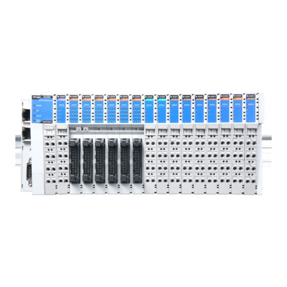
- Page 2 Introduction The ioLogik E4200 comes equipped with 2 Ethernet ports and 1 RS-232 port, making it suitable for remote monitoring and alarm system applications that require multiple I/O points of various types. LAN 1 LAN 0 Reset Button COM (RS-232 Port)
- Page 3 Step 2: Align the I/O module side by side with the network module and then push the I/O module until it touches the DIN-rail. Next, apply more force until the module clips to the DIN-rail. Removing the I/O Module from the DIN-Rail Step1: Use your finger or a screw driver to pull down the tab on the lower part of the module.
- Page 4 Installing the System Power Module The system power expansion module is designed to provide extra power when additional I/O expansion modules are connected. Each ioLogik E4200 can provide 1.5A @ 5 VDC. If you require more power for your installed I/O expansion modules, you will need to use an M-7001 module.
- Page 5 220 VAC Connecting the Power System Two 24 VDC power sources are required to power the ioLogik E4200. One 24 VDC power input is for system power, and the other 24 VDC power input is for the field I/O. For field installation, system power and field power are provided by different power supply systems.
- Page 6 Supported Modules DC-Digital Input Modules M-1800 8 digital inputs, sink, 24 VDC, removable terminal block M-1801 8 digital inputs, source, 24 VDC, removable terminal block M-1600 16 digital inputs, sink, 24 VDC, 20-pin header M-1601 16 digital inputs, source, 24 VDC, 20-pin header AC-Digital Input Modules M-1450 4 digital inputs,110 VAC, removable terminal block...
- Page 7 Accessories TB 1600 DIN-rail mounting screw terminal module with 20-pin connector • 20 pins, one-to-one assignment • Connector pitch: 3.81 mm • DIN-rail mounting type • Dimensions (W x L x H): 77.5 x 67.5 x 51 mm • RoHS compliant 20-pin to 20-pin flat cable •...
Need help?
Do you have a question about the ioLogik E4200 and is the answer not in the manual?
Questions and answers