Moxa Technologies ioLogik E2212 User Manual
Stand-alone active ethernet i/o server
Hide thumbs
Also See for ioLogik E2212:
- User manual (144 pages) ,
- Manual (84 pages) ,
- Quick installation manual (6 pages)
Table of Contents
Advertisement
Quick Links
Download this manual
See also:
Manual
Advertisement
Table of Contents

Related Manuals for Moxa Technologies ioLogik E2212


Summary of Contents for Moxa Technologies ioLogik E2212
- Page 1 E2212 User’s Manual Second Edition, January 2008 www.moxa.com/product Moxa Inc. Tel: +886-2-8919-1230 Fax: +886-2-8919-1231 Web: www.moxa.com Moxa Technical Support Worldwide: support@moxa.com The Americas: support@usa.moxa.com...
- Page 2 E2212 User’s Manual The software described in this manual is furnished under a license agreement, and may be used only in accordance with the terms of that agreement. Copyright Notice Copyright © 2008 Moxa Inc. All rights reserved. Reproduction without permission is prohibited.
-
Page 3: Table Of Contents
Table of Contents Chapter 1. Introduction ....................1-1 Overview ..........................1-2 Traditional Remote I/O....................1-2 Active Ethernet I/O....................... 1-2 Click&Go ........................1-2 Optional Liquid Crystal Display Module (LCM) ............1-3 Product Features ........................1-3 Package List ......................... 1-4 Product Specifications ......................1-5 Physical Dimensions (Unit = mm) .................. - Page 4 Watchdog Tab......................3-16 Click&Go Logic Tab ....................3-17 Server Context Menu......................3-17 Using TFTP to Import/Export Configuration ..............3-19 Using ioEventLog....................... 3-20 Installing ioEventLog ....................3-20 Basic Functions......................3-20 Configuration......................3-21 Checking Connected Devices ..................3-22 Opening Log Files ...................... 3-22 Clearing the Log ......................
- Page 5 Active I/O Messages....................5-15 Peer-to-Peer I/O......................5-16 Appendix A. Liquid Crystal Display Module (LCM) ............. A-2 LCM Controls........................A-2 LCM Options........................A-2 Appendix B. Modbus/TCP Address Mappings ............B-2 E2212 Modbus Mapping ......................B-2 0xxxx Read/Write Coils (Functions 1, 5, 15) ...............B-2 1xxxx Read Only Coils (Function 2)................B-13 3xxxx Read Only Registers (Function 4)..............B-13 4xxxx Read/Write Registers (Functions 3, 6, 16)............B-17...
-
Page 6: Chapter 1. Introduction
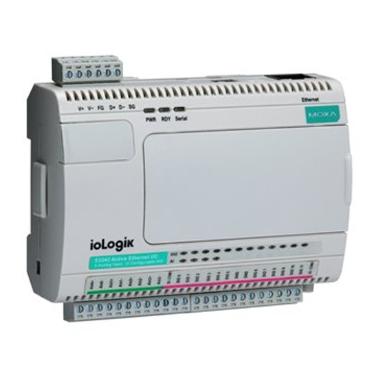
Introduction Chapter 1. The ioLogik E2212 is a stand-alone Active Ethernet I/O server that can connect sensors and on/off switches for automation applications over Ethernet and IP-based networks. The following topics are covered in this chapter: Overview Traditional Remote I/O Active Ethernet I/O Click&Go... -
Page 7: Overview
Introduction Overview The ioLogik E2212 is a member of the E2000 line of ioLogik Active Ethernet I/O servers, which are designed for intelligent, pro-active status reporting of attached sensors, transmitters, transducers, and valves over a network. It includes 2 MB of Flash ROM, 8 MB of SDRAM, and supports an optional hot-pluggable Liquid Crystal Display Module (LCM) to view and configure device settings. -
Page 8: Optional Liquid Crystal Display Module (Lcm)
The LCM can display network and I/O settings such as digital input mode and value. The ioLogik E2212’s IP address and netmask may also be configured using the LCM, and one LCM can be used to maintain and configure multiple ioLogik E2212 servers. -
Page 9: Package List
Ethernet to another ioLogik E2212. For typical 100 Mbps LANs, latency is only 100 ms. Power fail counter storage memory The ioLogik E2212 stores event counter values so that they are not lost during a power failure or disconnection. RoHS compliance As required by EU regulations, the ioLogik E2212 is fully RoHS-compliant. -
Page 10: Product Specifications
E2212 Series User’s Manual Introduction Product Specifications Interface 10/100BaseTx with MDI/MDIX, RJ45 Protocols Modbus/TCP, TCP/IP, UDP, DHCP, Bootp, SNMP(MIB for I/O and Network), HTTP, SNTP Protection 1.5KV magnetic isolation IP Address Fixed, dynamic (DHCP) Default: 192.168.127.254 Serial Interface RS-485 (2 wire): Data+, Data-, GND... -
Page 11: Physical Dimensions (Unit = Mm)
E2212 Series User’s Manual Introduction Environmental Operation Temperature -10 to 60°C (14 to 140°F), 5 to 95% RH Storage Temperature -40 to 85°C (-40 to 185°F), 50 to 95% RH Wiring I/O Cable Max. 14 AWG Certificaitons Shock, Freefall, Vibration,... -
Page 12: With Lcm
E2212 Series User’s Manual Introduction With LCM Hardware Reference Panel Guide NOTE: The reset button restarts the server and resets all settings to factory defaults. Use a pointed object such as a straightened paper clip to hold the reset button down for 5 sec. The RDY LED will turn red as you are holding the reset button down. -
Page 13: Pin Assignments
E2212 Series User’s Manual Introduction Pin Assignments System Bus Signal Signal Data+ SYNC Data- Ethernet Port Signal Signal TB1 (Power Input & RS-485 Connector) Signal (V+: 12 to 48V) TB2 (Digital Input and Output Terminal) Signal COM1 COM2 Signal... -
Page 14: Led Indicators
System error (steady) ioLogik E2212 is functioning normally Ready Green (flashing) Click&Go logic is active Green & red (flashing) ioLogik E2212 is in Safe Status Serial (flashing) Serial port is receiving or transmitting data I/O LEDs Green Status is ON DI ×... -
Page 15: Chapter 2. Initial Setup
Initial Setup Chapter 2. This chapter describes how to install the ioLogik E2212 Active Ethernet I/O Server. The following topics are covered in this chapter: Hardware Installation Connecting the Power Grounding the Unit Connecting to the Network Adding More I/O Channels... -
Page 16: Hardware Installation
R2000 I/O server. The two servers can be snapped together using the RS-485 system bus connector, as shown in the following figure. For the ioLogik E2212, additional digital I/O channels are added using the ioLogik R2110. For additional details, please refer to the ioLogik... -
Page 17: Setting The Rs-485 Baudrate
I/O devices. Also, unlike traditional Ethernet I/O products, the ioLogik E2212 can connect to dry contact, PNP, and NPN sensors at the same time. The sensor type determines your wiring approach, as shown in the following examples:... -
Page 18: Software Installation
Windows utility provided for the configuration and management of the ioLogik E2212 and attached I/O devices. It may be used from anywhere on the network to monitor and configure the ioLogik E2212. You may also configure some of the settings through the web console or optional LCM. - Page 19 E2212 Series User’s Manual Initial Setup Monitoring I/O status: Once your unit has been found by ioAdmin, you may view the status of all attached I/O devices on ioAdmin’s main screen. You may now use ioAdmin to setup or configure your unit. Please refer to Chapter 3 for...
-
Page 20: Chapter 3. Using Ioadmin
Using ioAdmin Chapter 3. In this chapter, we explain how to use ioAdmin to configure your ioLogik. The following topics are covered in this chapter: Introduction to ioAdmin Features of ioAdmin ioAdmin Main Screen Main Screen Overview Wiring Guide Menu Items Main Window ioAdmin Administrator Functions I/O Configuration Tab (Administrator) -
Page 21: Introduction To Ioadmin
Windows utility provided with your ioLogik E2212. ioAdmin’s graphical-user interface gives you easy access to all status information and settings. The ioLogik E2212 also supports configuration by web console and by optional LCM, but full configuration and management is only available through ioAdmin. - Page 22 E2212 Series User’s Manual Using ioAdmin Configuration File ioAdmin allows the entire configuration of the ioLogik E2212 to be saved as a file. The file is viewable as text and can serve three purposes: as a record or backup of...
-
Page 23: Ioadmin Main Screen
E2212 Series User’s Manual Using ioAdmin ioAdmin Main Screen Main Screen Overview This is ioAdmin’s main screen. The main window defaults to the I/O Configuration tab, which displays a figure of your unit with the status of every I/O channel. The other tabs in the main window take you to server and network settings, and further functions are available when you log on as an administrator. -
Page 24: Wiring Guide
Using ioAdmin Wiring Guide ioAdmin provides a wiring guide for the ioLogik E2212. You may access the wiring guide by right-clicking the ioLogik figure in the I/O Configuration tab. Select “Wiring Guide” in the submenu to open a help file showing the unit’s wiring information and electrical characteristics. -
Page 25: Menu Items
E2212 Series User’s Manual Using ioAdmin Menu Items File From the File menu, you can export the list of I/O servers that are currently displayed in the navigation panel. You also can import a list of I/O servers into ioAdmin. -
Page 26: Sort
E2212 Series User’s Manual Using ioAdmin TCP Socket Timeout Interval allows you to select the preferred timeout value for TCP socket communication. COM Port Setting is used to set the parameters for Modbus communciation, such as baudrate, data bits, and timeout interval. For most applications, this will involve connecting to ioLogik R-Series devices. -
Page 27: Main Window
E2212 Series User’s Manual Using ioAdmin Main Window I/O Configuration Tab (General) The I/O Configuration tab shows the status of every I/O channel. This is the default tab when you first open ioAdmin. DI channels are listed on the left and DO channels are listed on the right. The four selectable channels will be listed on the left or the right according to the selected mode. -
Page 28: Server Settings Tab (General)
The Server Settings tab is where you log in as an administrator. This is required in order to gain access to the ioLogik E2212 configuration options. If no administrator password has been set up, simply click Login and leave the Password for entry field blank. Please refer to the ioAdmin Administrator Functions section later on in this chapter for more detail. -
Page 29: Ioadmin Administrator Functions
Configuring Digital Input Channels The ioLogik E2212 provides up to 12 digital input (DI) channels, with 8 fixed DI channels (DI-0 to DI-7) and 4 channels that can be configured as DI or DO channels (DIO-8 to DIO-11). Software filtering is used to control switch bounces. - Page 30 E2212 Series User’s Manual Using ioAdmin A DI channel can be set to “DI” or “Event Counter” mode. In DI mode, the specifications are as follows: Type Logic 0 (OFF) Logic 1 (ON) Dry contact close to GND open...
- Page 31 E2212 Series User’s Manual Using ioAdmin The ioLogik E2212 provides up to 12 digital output (DO) channels with 8 fixed DO channels (DO-0 to DO-7) and 4 channels that can be configured as DI or DO channels (DIO-8 to DIO-11).
-
Page 32: Server Settings Tab (Administrator)
To switch to between DI and DO channel operation, select the desired mode in the I/O Direction field under Power On Settings. After clicking Apply, you will need to restart the ioLogik E2212 for the new setting to take effect. -
Page 33: Network Tab
E2212 Series User’s Manual Using ioAdmin Network Tab The Network tab is available after you log in as an administrator. You may configure IP settings, Modbus/TCP Alive Check Timeout settings, DNS settings, Serial settings, SNMP settings, and Web Access settings for the ioLogik. -
Page 34: Firmware Update Tab
SNMP Settings The ioLogik E2212 provides SNMP v2 (Simple Network Management Protocol) to allow monitoring of network and I/O devices with SNMP Network Management software. It is useful for building automation and telecom applications. Use these fields to enable SNMP and set the read and write community strings. -
Page 35: Watchdog Tab
E2212 Series User’s Manual Using ioAdmin ATTENTION Do not interrupt the firmware update process! An interruption in the process may result in your device becoming unrecoverable. After the firmware is updated, the ioLogik will restart and you will have to log in again to access administrator functions. -
Page 36: Click&Go Logic Tab
Please refer to Chapter 5 for more detailed information on defining rules. Changes in the Click&Go Logic tab are not effective until the ioLogik E2212 is restarted, just like changes made in other tabs. After logging back in as an administrator and returning to the Click&Go Logic tab, click Download to view the current ruleset. - Page 37 E2212 Series User’s Manual Using ioAdmin Connect Select this command to try connecting over the network to the selected ioLogik. Disconnect Select this command to drop the network connection with the selected ioLogik. Delete I/O Server Select this command to remove the selected ioLogik.
-
Page 38: Using Tftp To Import/Export Configuration
E2000 I/O servers support the use of TFTP to import or export configuration files. The following is an example using Windows TFTP and an ioLogik E2212 with an IP address of 192.168.127.254: 1. -
Page 39: Using Ioeventlog
Windows utility provided for the monitoring of the ioLogik E2212 and attached I/O devices. It may be used from anywhere on the network to monitor the ioLogik E2212. Installation from CD: Insert the Document and Software CD into the host computer. Run SETUP.EXE, which is located in the root directory. -
Page 40: Configuration
E2212 Series User’s Manual Using ioAdmin Configuration In the System menu, select Settings to configure ioEventLog. The Alarm Listen Port is the TCP port number that will be monitored for status events. You can modify this setting as necessary to receive signals through a firewall. It will need to match the settings for the ioLogik server that is being monitored. -
Page 41: Checking Connected Devices
E2212 Series User’s Manual Using ioAdmin Checking Connected Devices You can see which I/O servers are already connected to ioEventLog by selecting Connected Device List from the Connection menu. You will be prompted to view which devices are connected. -
Page 42: Chapter 4. Web Console Configuration
Web Console Configuration Chapter 4. The ioLogik E2212’s built in web console can be used to configure many of the ioLogik’s settings. The following topics are covered: Introduction to the Web Console Basic Settings Network Settings General Settings Ethernet Configurations... -
Page 43: Introduction To The Web Console
E2212 Series User’s Manual Web Console Configuration Introduction to the Web Console The ioLogik web console is a browser-based configuration utility. When the ioLogik is connected to your network, you may enter the server’s IP address in your web browser to access the web console. -
Page 44: Basic Settings
E2212 Series User’s Manual Web Console Configuration Basic Settings On the Basic Settings page, you may set the ioLogik’s system time or provide the IP address of a time server for time synchronization. Network Settings General Settings On the General Settings page, you may assign a server name and location to assist you in differentiating between different I/O servers. -
Page 45: Ethernet Configurations
E2212 Series User’s Manual Web Console Configuration Ethernet Configurations On the Ethernet Configurations page, you may set up a static or dynamic IP address for the ioLogik, as well as the subnet mask and gateway address. RS-485 Settings On the RS-485 Settings page, you may view the serial communication parameters, but no configuration changes are allowed. - Page 46 E2212 Series User’s Manual Web Console Configuration You may click on a channel for that channel’s configuration options. DI channels can operate in DI mode or Event Counter mode. Software filtering is used to control switch bounces. The filter is configurable in multiples of 0.5 ms and accepts values between 1 and 65535.
-
Page 47: Do Channels
E2212 Series User’s Manual Web Console Configuration DO Channels On the DO Channels page, you may view the status of each DO (digital output) channel. Both fixed DO channels and DIO channels that are acting as DO channels will be displayed. -
Page 48: System Management
E2212 Series User’s Manual Web Console Configuration System Management Accessible IP Settings On the Accessible IP Settings page, you may control network access to the ioLogik by allowing only specified IP addresses. When the accessible IP list is enabled, a host’s IP address must be listed in order to have access to the ioLogik. -
Page 49: Snmp Agent
E2212 Series User’s Manual Web Console Configuration SNMP Agent On the SNMP Agent page, you may enable SNMP and set the read and write community strings. The ioLogik provides SNMP v2 (Simple Network Management Protocol) to allow monitoring of network and I/O devices with SNMP Network Management software. -
Page 50: Import System Config
E2212 Series User’s Manual Web Console Configuration Import System Config On the Import System Config page, you may import a configuration onto the ioLogik server. The configuration file can be generated by ioAdmin or through the web console. This function can be used to duplicate settings between ioLogik servers. -
Page 51: Change Password
Web Console Configuration Change Password For all changes to the ioLogik E2212’s password protection settings, you will first need to enter the old password. Leave this blank if you are setting up password protection for the first time. To set up a new password or change the existing password, enter your desired password under both New password and Confirm password. -
Page 52: Chapter 5. Click&Go Logic
Click&Go Logic Chapter 5. Click&Go Logic was developed by Moxa to provide an easy way to program your ioLogik E2212 for Active Ethernet I/O operation. In this chapter, we will show you how Click&Go Logic works and how to use it to develop your Active Ethernet I/O system. -
Page 53: Overview
TCP/UDP messages to up to 10 hosts at a time. Click&Go can also be used to map an input channel on one ioLogik E2212 to an output channel on another ioLogik E2212, for peer-to-peer I/O communication. Up to five different IP addresses can be entered as the output destination. -
Page 54: Click&Go Logic Basics
DO operation can also be automated through DI trigger conditions or mapped directly to a remote DI channel on another ioLogik E2212. In the main screen, you will see a list of the rules in the current ruleset. Double click on a rule to open... - Page 55 Logic rules and peer-to-peer I/O rules. Logic rules are used for DI event-based triggers, whereas peer-to-peer I/O rules are used for mapping I/O channels between two ioLogik E2212 units. The Equivalent Logic Statement at the bottom shows a real-time text-based summary of the rule that you are defining.
-
Page 56: Defining Logic Rules
E2212 Series User’s Manual Click&Go Logic Defining Logic Rules IF Conditions Under the IF column, you may set up to 3 sensor conditions that must be satisfied for the actions under the THEN column to take place. As soon as the IF conditions are satisfied, the specified THEN action is performed. - Page 57 E2212 Series User’s Manual Click&Go Logic No Edge Detection In this scenario, the rule checks each sensor for “on” status, so edge detection is not involved. As long as the sensors remain on, the required conditions are satisfied, and the THEN actions will repeat at interval N.
- Page 58 E2212 Series User’s Manual Click&Go Logic Edge Detection for Two Conditions In this scenario, the rule checks DI-0 and DI-1 for a change in status and DI-2 for status only. The repeat interval will not have an effect if the AND relationship is used, because the two edge conditions can never be sustained over a length of time.
-
Page 59: Then Actions
E2212 Series User’s Manual Click&Go Logic THEN Actions Under the THEN column, you may specify up to 3 actions that will be performed when the conditions under the IF column are satisfied. Possible actions include changing the status of a DO channel, starting or stopping an Event Counter, or sending a message by SNMP trap, TCP, UDP, or e-mail. - Page 60 E2212 Series User’s Manual Click&Go Logic Active Message The Active Message option sends a customized message to one or more IP destinations by TCP or UDP. Click the memo icon to configure the message and parameters. When a message has been triggered, you may view the outgoing message in the Message Monitor tab.
- Page 61 E2212 Series User’s Manual Click&Go Logic SNMP trap The SNMP trap option sends an SNMP trap to one or more IP destinations. You may select a trap number between 1 and 20. (You may need to consult with your network administrator to determine how trap numbers will be used and defined in your network.) Click the memo icon to specify up to...
-
Page 62: Defining Peer-To-Peer I/O Rules
Ethernet from a DI channel on one ioLogik E2212 to the DO channel on another ioLogik E2212. Peer-to-peer I/O makes it easy for a pushbutton to have direct control of an LED in another room, building, or even city. -
Page 63: Configuring Input Module
IP… and enter up to five IP addresses as destinations. Each IP address should belong to an ioLogik E2212 unit that will act as an output module for peer-to-peer I/O operation. If you wish, you may set up additional peer-to-peer I/O rules in order to mirror input channels to more than five destinations. -
Page 64: Configuring Output Module
Only DI channels that are set to DI mode can be mirrored on the output module. Peer-to-peer I/O will not function with Event Counter channels. The ioLogik E2212 can simultaneously act as both an input module and an output module. Input module operation would be configured in one rule, and another rule would be used to configure output module operation. -
Page 65: Working With Click&Go Rulesets
Active Ethernet I/O system. The ruleset must be activated for the ioLogik to commence Active Ethernet I/O operation, as follows: 1. The ruleset must first be downloaded from ioAdmin onto the ioLogik E2212. You may do so by clicking Download in the Ruleset Management bar. -
Page 66: Active I/O Messages
E2212 Series User’s Manual Click&Go Logic 4. Select Enable Logic. 5. Select DI-0 as your condition in the first IF field, and set its value to ON. 6. Select DO-0 as your action in the first THEN field, and set its value ON. -
Page 67: Peer-To-Peer I/O
Rule 0: Send I/O status to 192.168.127.3 1. In ioAdmin, make sure that you have searched for and selected the correct ioLogik E2212 server, at IP address 192.168.127.154. Also, make sure you are logged in on the Server Settings tab. - Page 68 Rule 1: DI-1 at 192.168.127.154 mapped to DO-1 1. In ioAdmin, make sure that you have searched for and selected the correct ioLogik E2212 server, at IP address 192.168.127.3. Also, make sure you are logged in on the Server Settings tab. Go to the Click&Go Logic tab.
-
Page 69: Appendix A. Liquid Crystal Display Module (Lcm
Liquid Crystal Display Module (LCM) Appendix A. The ioLogik E2212 supports an optional detachable Liquid Crystal Display Module (LCM) for easier field maintenance. The LCM is hot-pluggable and can be used to configure the network settings or display other settings. When plugged in, the LCM displays the ioLogik “home page,” and pressing any button takes you into the settings and configuration. - Page 70 E2212 Series User’s Manual Display Explanation / Actions Enter this submenu to display information and settings for the network: ethernet link mac address ip mode <ioLogik E2212> ip address network netmask gateway dns server-1 dns server-2 Enter this submenu to display information about the Click&Go Logic ruleset currently loaded on the ioLogik:...
-
Page 71: Appendix B. Modbus/Tcp Address Mappings
Modbus/TCP Address Mappings Appendix B. E2212 Modbus Mapping 0xxxx Read/Write Coils (Functions 1, 5, 15) Reference Address Data Type Description CH0 DO value 00001 0x0000 1 bit 0: off 1: on CH1 DO value 00002 0x0001 1 bit 0: off 1: on CH2 DO value 00003... - Page 72 E2212 Series User’s Manual Modbus/TCP Address Mappings Reference Address Data Type Description CH3 DO power-on value 00016 0x000F 1 bit 0: off 1: on CH4 DO power-on value 00017 0x0010 1 bit 0: off 1: on CH5 DO power-on value...
- Page 73 E2212 Series User’s Manual Modbus/TCP Address Mappings Reference Address Data Type Description CH0 DO pulse operate status 00037 0x0024 1 bit 0: off 1: on CH1 DO pulse operate status 00038 0x0025 1 bit 0: off 1: on CH2 DO pulse operate status...
- Page 74 E2212 Series User’s Manual Modbus/TCP Address Mappings Reference Address Data Type Description CH9 DO power-on pulse operate status 00058 0x0039 1 bit 0: off 1: on CH10 DO power-on pulse operate status 00059 0x003A 1 bit 0: off 1: on...
- Page 75 E2212 Series User’s Manual Modbus/TCP Address Mappings Reference Address Data Type Description CH6 DI counter status 00079 0x004E 1 bit 0: off 1: on CH7 DI counter status 00080 0x004F 1 bit 0: off 1: on CH8 DI counter status...
- Page 76 E2212 Series User’s Manual Modbus/TCP Address Mappings Reference Address Data Type Description CH5 DI clear count value Read: 0: no action 00090 0x0059 1 bit Write: 1: clear counter value 0: return illegal data value CH6 DI clear count value...
- Page 77 E2212 Series User’s Manual Modbus/TCP Address Mappings Reference Address Data Type Description CH0 DI overflow status Read: 0: normal 1: overflow 00097 0x0060 1 bit Write: 0: clear overflow status 1: return illegal data value CH1 DI overflow status...
- Page 78 E2212 Series User’s Manual Modbus/TCP Address Mappings Reference Address Data Type Description CH7 DI overflow status Read: 0: normal 1: overflow 00104 0x0067 1 bit Write: 0: clear overflow status 1: return illegal data value CH8 DI overflow status...
- Page 79 E2212 Series User’s Manual Modbus/TCP Address Mappings Reference Address Data Type Description CH0 DI power-on status 00121 0x0078 1 bit 0: off 1: on CH1 DI power-on status 00122 0x0079 1 bit 0: off 1: on CH2 DI power-on status...
- Page 80 E2212 Series User’s Manual Modbus/TCP Address Mappings Reference Address Data Type Description CH9 DI safe operate status 00142 0x008D 1 bit 0: off 1: on CH10 DI safe operate status 00143 0x008E 1 bit 0: off 1: on CH11 DI safe operate status...
- Page 81 E2212 Series User’s Manual Modbus/TCP Address Mappings Reference Address Data Type Description DIO 0 00157 0x009C 1 bit 1: output DO mode 0: input DI mode DIO 1 00158 0x009D 1 bit 1: output DO mode 0: input DI mode...
-
Page 82: 1Xxxx Read Only Coils (Function 2
E2212 Series User’s Manual Modbus/TCP Address Mappings 1xxxx Read Only Coils (Function 2) Reference Address Data Type Description 10001 0x0000 1 bit CH0 DI value 10002 0x0001 1 bit CH1 DI value 10003 0x0002 1 bit CH2 DI value... - Page 83 E2212 Series User’s Manual Modbus/TCP Address Mappings Reference Address Data Type Description 30022 0x0015 1 word CH10 DI count value lo-byte 30023 0x0016 1 word CH11 DI count value hi-byte 30024 0x0017 1 word CH11 DI count value lo-byte...
- Page 84 E2212 Series User’s Manual Modbus/TCP Address Mappings Reference Address Data Type Description Firmware revision: Word 0 hi byte = major (A) 0x102D to Word 0 lo byte = minor (B) 34142 to 0x102E 2 word 34143 Word 1 hi byte = release (C)
- Page 85 E2212 Series User’s Manual Modbus/TCP Address Mappings Reference Address Data Type Description 0x103D 34158 1 word LCM loop count (event/sec) (4157) 0x103E to 34159 to 0x103F 2 word System elapsed time (in sec) 34160 (4158 to 4159) 0x1040 34161...
-
Page 86: 4Xxxx Read/Write Registers (Functions 3, 6, 16
E2212 Series User’s Manual Modbus/TCP Address Mappings Reference Address Data Type Description 0x2500 39473 1word Report E2212 DI/DO channel number (9472) 0x2501 39474 1 word Report AI/AO channel number (9473) 0x2502 39475 1word Report RTD/TC channel number (9474) 312289... - Page 87 E2212 Series User’s Manual Modbus/TCP Address Mappings 40021 0x0014 word CH10 DO pulse output count value hi- word 40022 0x0015 word CH10 DO pulse output count value lo- word 40023 0x0016 word CH11 DO pulse output count value hi- word...
- Page 88 E2212 Series User’s Manual Modbus/TCP Address Mappings CH7 DO mode 40056 0x0037 word 0: DO 1: pulse CH8 DO mode 40057 0x0038 word 0: DO 1: pulse CH9 DO mode 40058 0x0039 word 0: DO 1: pulse CH10 DO mode...
- Page 89 E2212 Series User’s Manual Modbus/TCP Address Mappings CH5 DI mode 0: DI 40078 0x004D word 1: count Other: return illegal data value CH6 DI mode 0: DI 40079 0x004E word 1: count Other: return illegal data value CH7 DI mode...
- Page 90 E2212 Series User’s Manual Modbus/TCP Address Mappings CH7 DO value 40092 0x005B 1 word 0: off 1: on CH8 DO value 40093 0x005C 1 word 0: off 1: on CH9 DO value 40094 0x005D 1 word 0: off 1: on...
- Page 91 E2212 Series User’s Manual Modbus/TCP Address Mappings CH4 DO safe mode value 40113 0x0070 1 word 0: off 1: on CH5 DO safe mode value 40114 0x0071 1 word 0: off 1: on CH6 DO safe mode value 40115...
- Page 92 E2212 Series User’s Manual Modbus/TCP Address Mappings CH1 DO power-on pulse operate status 40134 0x0085 1 word 0: stop 1: start CH2 DO power-on pulse operate status 40135 0x0086 1 word 0: stop 1: start CH3 DO power-on pulse operate status...
- Page 93 E2212 Series User’s Manual Modbus/TCP Address Mappings CH10 DO safe mode pulse operate status 40155 0x009A 1 word 0: stop 1: start CH11 DO safe mode pulse operate status 40156 0x009B 1 word 0: stop 1: start CH0 DI counter operate status...
- Page 94 E2212 Series User’s Manual Modbus/TCP Address Mappings CH2 DI clear count value Read: 0: no action 40171 0x00AA 1 word Write: 1: clear counter value 0: return illegal data value(0x03) CH3 DI clear count value Read: 0: no action...
- Page 95 E2212 Series User’s Manual Modbus/TCP Address Mappings CH9 DI clear count value Read: 0: no action 40178 0x00B1 1 word Write: 1: clear counter value 0: return illegal data value(0x03) CH10 DI clear count value Read: 0: no action...
- Page 96 E2212 Series User’s Manual Modbus/TCP Address Mappings CH4 DI overflow status Read: 0: normal 1: overflow 40185 0x00B8 1 word Write: 0: clear overflow status 1: return illegal data value (0x03) CH5 DI overflow status Read: 0: normal 1: overflow...
- Page 97 E2212 Series User’s Manual Modbus/TCP Address Mappings CH11 DI overflow status Read: 0: normal 1: overflow 40192 0x00BF 1 word Write: 0: clear overflow status 1: return illegal data value (0x03) CH0 DI counter trigger 40193 0x00C0 1 word...
- Page 98 E2212 Series User’s Manual Modbus/TCP Address Mappings CH6 DI power-on counter operate status 40211 0x00D2 1 word 0: stop 1: start CH7 DI power-on counter operate status 40212 0x00D3 1 word 0: stop 1: start CH8 DI power-on counter operate status...
- Page 99 E2212 Series User’s Manual Modbus/TCP Address Mappings CH2 DI set channel 40231 0x00E6 1 word Power-off storage enable ON/OFF 1: on 0: off CH3 DI set channel 40232 0x00E7 1 word Power-off storage enable ON/OFF 1: on 0: off...
-
Page 100: 5Xxxx Write Registers (Function 8
E2212 Series User’s Manual Modbus/TCP Address Mappings 5xxxx Write Registers (Function 8) Sub-function Data Field (Request) Data Field (Response) Description 0x0001 0xFF00 Echo Request Data Reboot 0x0001 0x55AA Echo Request Data Reset with factory default B-31... -
Page 101: Appendix C. Used Network Port Numbers
Used Network Port Numbers Appendix C. E2212 Network Port Usage Port Type Usage BOOTPC DHCP Export/import file Web Server SNMP Modbus Communication 4800 Auto search 9020 Peer-to-Peer function 9000 Active Message (Default) 9000 Active Message (Default) 4040 ioEventLog... -
Page 102: Appendix D. Snmp Agents With Mib Ii, Rs-232-Like Groups
SNMP Agents with MIB II, Appendix D. RS-232-like Groups RFC1213 MIB II Supported SNMP Variables The following SNMP variables are built into the ioLogik firmware and are compliant with RFC1213 MIB II. System MIB SysDescr SysContact SysServices SysObjectID SysName SysUpTime SysLocation Interfaces MIB ifNumber... - Page 103 E2212 Series User’s Manual SNMP MIBII IP MIB ipInDelivers ipAdEntReasmMaxSize ipNetToMediaPhysAddress ipOutRequests ipRouteDest ipNetToMediaNetAddress ipOutDiscards ipRouteIfIndex ipNetToMediaType ipOutNoRoutes ipRouteMetric1 ipRoutingDiscards ipReasmtimeout ipRouteMetric2 ipReasmReqds ipRouteMetric3 ipReasmOKs ipRouteMetric4 IcmpInmsgs IcmpIntimestamps IcmpOutRedirects IcmpInErrors IcmpTimestampReps IcmpOutechos IcmpInDestUnreachs IcmpInAddrMasks IcmpOutEchoReps IcmpIntimeExcds IcmpOutMsgs IcmpOuttimestamps IcmpInParmProbs...
- Page 104 E2212 Series User’s Manual SNMP MIBII SNMP MIB snmpInPkts snmpIngenErrs snmpOutBadValues snmpOutPkts nnmpInTotalReqVars snmpOutGenErrs snmpInBadVersions snmpIntotalSetVars snmpOutGetRequests snmpInBadCommunityNames snmpInGetRequests snmpOutGetNexts snmpInBadCommunityUses snmpInGetNexts snmpOutSetrequests snmpInASNParseErrs snmpInSetRequests snmpOutGetResponses snmpInTooBigs snmpIngetResponses snmpOutTraps snmpInNoSuchNames snmpInTraps snmpEnableAuthenTraps snmpInBadValues snmpOutTooBigs snmpInReadOnlys snmpOutNoSuchNames Private MIB File and SNMP Variables Moxa also provides an SNMP to I/O MIB file that can help you monitor I/O status with SNMP software.
- Page 105 E2212 Series User’s Manual SNMP MIBII Moxa IO MIB DI02-Status DO02-Mode DIO09-Index DI02-Filter DO02-Status DIO09-Type DI02-Tigger DO02-LowWidth DIO09-Mode DI03-Index DO02-HighWidth DIO09-Status DI03-Type DO02-PulseStart DIO09-Filter DI03-Mode DO03-Index DIO09-Tigger DI03-Status DO03-Type DIO09-LowWidth DI03-Filter DO03-Mode DIO09-HighWidth DI03-Tigger DO03-Status DIO09-PulseStart DI04-Index DO03-LowWidth DIO10-Index...
-
Page 106: Appendix E. Factory Default Settings
Factory Default Settings Appendix E. The factory default settings for the ioLogik E2212 are as follows: IP address: 192.168.127.254 255.255.0.0 Netmask: None Gateway: Communication Watchdog: Disable Modbus/TCP Alive Check: Modbus/TCP Timeout Interval: 60 sec DI Mode: DI Safe Status: 10 ×... -
Page 107: Appendix F. Cable Wiring
Cable Wiring Appendix F. Device Wiring Diagrams Digital Input Dry Contact Digital Input Wet Contact NPN Type Sensors Connection... -
Page 108: Digital Output Sink Mode
E2212 Series User’s Manual Cable Wiring PNP Type Sensors Connection Digital Output Sink Mode... -
Page 109: Circuit Diagrams
E2212 Series User’s Manual Cable Wiring Circuit Diagrams Digital Input Channel Dry Contact Wet Contact... - Page 110 E2212 Series User’s Manual Cable Wiring PNP Type Sensor Contact NPN Type Sensor Contact...
-
Page 111: Digital Output Channel
E2212 Series User’s Manual Cable Wiring Digital Output Channel The DO Field Power Indication is a channel for driving the DO field power LED. Configurable DIO Channel...
Need help?
Do you have a question about the ioLogik E2212 and is the answer not in the manual?
Questions and answers