
Related Manuals for Moxa Technologies ioLogik E4200


Summary of Contents for Moxa Technologies ioLogik E4200
- Page 1 E4200 User’s Manual Edition 4.2, April 2017 www.moxa.com/product © 2017 Moxa Inc. All rights reserved.
- Page 2 E4200 User’s Manual The software described in this manual is furnished under a license agreement and may be used only in accordance with the terms of that agreement. Copyright Notice © 2017 Moxa Inc. All rights reserved. Trademarks The MOXA logo is a registered trademark of Moxa Inc.
-
Page 3: Table Of Contents
Installing the Field Power Module ......................2-6 Connecting the Power System ......................2-7 Connecting to the Network ........................2-7 ioLogik E4200 Active Ethernet Network Adaptor ................2-7 Configuring Your Network Architecture ................... 2-8 Utilities ............................. 3-1 Introduction to Modular ioAdmin ......................3-2 Features of Modular ioAdmin...................... - Page 4 Ethernet Configuration ......................... 4-4 Route Table ..........................4-5 I/O Module ............................4-5 System Management ........................... 4-6 Accessible IP Settings ........................4-6 SNMP Agent ..........................4-7 Network Connection ........................4-7 Firmware Update ......................... 4-8 Import System Config ........................4-8 Export System Config ........................4-8 Change password ..........................
- Page 5 RFC1213 MIB-II supported SNMP variables: ................... E-2 Private MIB File and SNMP Variables ..................... E-3 Factory Default Settings ........................F-1 FCC ..............................G-1 FCC Statement ..........................G-1 FCC Warning! ............................ G-1...
-
Page 6: Introduction
Introduction The ioLogik Active Ethernet modular I/O family of advanced, slice-type network I/O products with local intelligence can connect sensors and on/off switches for automation applications over Ethernet and IP-based networks. The following topics are covered in this chapter: ioLogik Active Ethernet Modular I/O System Overview ... -
Page 7: Iologik Active Ethernet Modular I/O System Overview
E4200 Introduction ioLogik Active Ethernet Modular I/O System Overview The ioLogik Active Ethernet modular I/O family of slice-type network I/O products can connect sensors and on/off devices in any combination and can transfer the captured data or device status to a host computer via an Ethernet or IP-based network. -
Page 8: Product Features
Alarm messages can be automatically sent through the RS-232 COM port when the I/O is connected to a GPRS modem, such as Moxa’s OnCell 2111 or OnCell 2151. Built-in Web Console The ioLogik E4200 includes a pre-installed web console that allows you to monitor the I/O status via a web browser. -
Page 9: Package Checklist
NOTE: Please notify your sales representative if any of the above items are missing or damaged. Product Descriptions Detailed specifications for the ioLogik E4200 are available in the software’s product specification help file. Refer to the help file for more information. Models supported by this manual are:... -
Page 10: Temperature Input Modules
E4200 Introduction Temperature Input Modules M-6200 2 analog inputs, RTD, removable terminal block M-6201 2 analog inputs, thermocouple, removable terminal block Analog Output Modules M-4202 2 analog outputs, 4 to 20 mA, 12-bit, removable terminal block (phased out in May 2009) -
Page 11: I/O Module
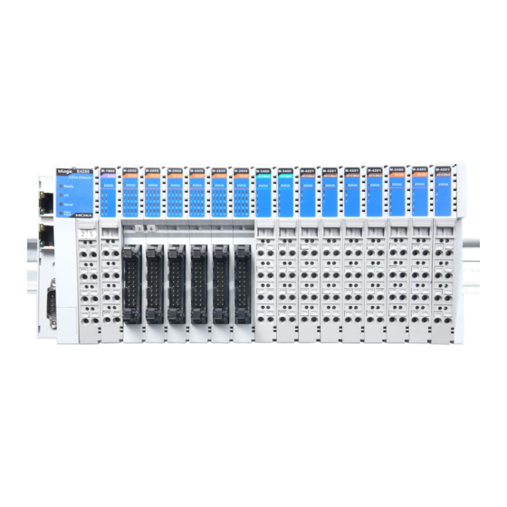
E4200 Introduction I/O Module Unit: mm; W x H x D: 14 x 99.8 x 70 mm Hardware Reference Panel Guide LED Indicators Ethernet LAN 1 Ready: System Status I/O: Module Detection Serial: RS-232 Status Ethernet LAN 0 Field Power: Power for I/O Points... -
Page 12: Hardware Specifications
E4200 Introduction Hardware Specifications Ethernet: 2 x 10/100 Mbps: 2 MACs, 2 IPs, RJ45 connectors Protection: 1.5 KV magnetic isolation Protocols: Modbus/TCP, TCP/IP, UDP, DHCP, Bootp, SNMP, HTTP, SNTP, SMTP Serial Communication Interface: 1 x RS-232 (9-pin D-Sub, male) -
Page 13: Led Indicators
E4200 Introduction LED Indicators LED Indicators for Network Adaptors Group Pins/Description Printed label Ethernet On the Plug Green: The power is on and the system is working normally Green-Flashing: Click&Go is active Ready Ready Red-Flashing: System error Off: No power... -
Page 14: Initial Setup
Installing the RTB on the I/O Module Installing the System Power Module Installing the Field Power Module Connecting the Power System Connecting to the Network ioLogik E4200 Active Ethernet Network Adaptor Configuring Your Network Architecture... -
Page 15: System Architecture
Initial Setup System Architecture The ioLogik E4200 modular I/O consists of a network adaptor that supports Ethernet and up to 16 I/O modules. • The ioLogik E4200 Active Ethernet network adaptor is the brains of the system. It is responsible for collecting information from each I/O module and deciding what parameters to use to operate the I/O module. -
Page 16: Installing An I/O Module On A Din Rail
E4200 Initial Setup Installing an I/O Module on a DIN Rail Step1: Align the I/O module side by side with the network adaptor, making sure that the upper and lower rails are hooked together. Step 2: Align the I/O module side by side with the network module and then push the I/O module until it... -
Page 17: Removing The I/O Module From The Din Rail
E4200 Initial Setup Removing the I/O Module from the DIN Rail Step1: Use your finger or a screw driver to pull down the tab on the lower part of the module. Step2: While still holding down the tab, pull out the module. -
Page 18: Removing The Rtb (Removable Terminal Block) From The I/O Module
The system power expansion module is designed to provide extra power when additional I/O expansion modules are connected. Each ioLogik E4200 can provide 1.5 A @ 5 VDC. If you require more power for your installed I/O modules, you will need to use an M-7001 module. However, please note that the M-7001 can only... -
Page 19: Installing The Field Power Module
The field power distributor is designed to isolate different field voltages. Most of the field power DIO/AIO modules for the ioLogik E4200 series are 24 VDC. If you need to connect 110 VAC, 230 VAC digital input or output modules, you must use the Field Power Distributor to isolate different field powers within a single ioLogik E4200 system. -
Page 20: Connecting The Power System
Note that you can insert any LAN port to make the configuration setting work. 1. Connect the ioLogik E4200 to the host PC with an Ethernet cable. For initial setup of the ioLogik E4200, we recommend configuring the ioLogik E4200 using a direct connection to a host computer, rather than remotely over the network. -
Page 21: Configuring Your Network Architecture
After connecting the ioLogik E4200, you will need to configure the network. Refer to the following figure for an example. To manage the ioLogik E4200 from Host 1, use the parameters in the following table to add a routing rule to the ioLogik E4200’s routing table: Destination 192.168.18.10... -
Page 22: Utilities
Utilities In this chapter, we introduce software utilities you can use when configuring the Windows-based ioLogik Active Ethernet modular I/O system. The software utilities include: 1. Modular ioAdmin: The main utility that allows you to configure, monitor, and edit Click&Go. 2. -
Page 23: Introduction To Modular Ioadmin
The ioLogik Modular I/O can be managed and configured over the Ethernet using Modular ioAdmin, a Windows utility provided with your ioLogik E4200. Modular ioAdmin’s graphical user interface gives you easy access to all status information and settings. Although the ioLogik E4200 also supports configuration by web console, full configuration and management is only available through Modular ioAdmin. -
Page 24: Getting Started
E4200 Utilities Getting Started Installing Modular ioAdmin Utility Modular ioAdmin can be downloaded from Moxa’s website. 1. Installing Modular ioAdmin from website: a. First click on the following link to access the website’s search utility: http://www.moxa.com/support/search.aspx?type=soft b. When the web page opens, enter the model name of your product in the search box. - Page 25 system Network Interface. After the ioLogik E4200 is displayed in the main window, select Adaptor Settings and then click login. The I/O modules will be automatically detected and shown on the main window of the I/O configuration tab.
- Page 26 If this is not a first-time installation, the Module Order Error window might appear. If the initial installation is successful, the ioLogik E4200 will memorize all settings and current module combinations. If the module combination changes, the ioLogik E4200 will detect an unmatched module combination event and show a warning window as pictured below.
- Page 27 This is Modular ioAdmin’s main screen. The main window defaults to the I/O Configuration tab, which displays a figure of the ioLogik E4200 and the status of every I/O channel below it. The other tabs in the main window take you to device and network settings, and further functions are available when you log on as an administrator.
-
Page 28: Functions On The Menu Bar
E4200 Utilities Functions on the Menu Bar File From the File menu, you can export the Server List, which contains a list of ioLogik devices that are currently displayed in the navigation panel. You also can import a list of ioLogik I/Os into Modular ioAdmin. -
Page 29: Navigation Panel
E4200 Utilities change the configuration, click I/O Status Refresh Interval under the System menu, and then adjust the data refresh rate. Note that the unit is in 10 msec increments, so if you enter 100, the refresh rate becomes 1 sec. -
Page 30: Server Context Menu
E4200 Utilities Server Context Menu The server context menu is accessed by right clicking on the server model name in the navigation panel. Connect Select this command if you want Modular ioAdmin to attempt to reconnect over the network to the selected ioLogik I/O. -
Page 31: Quick Links
Main Window (General) I/O Configuration Tab (General) If you are not logged in, the I/O Configuration tab shows the picture of the ioLogik E4200 without I/O modules. This is the default tab when you first open Modular ioAdmin. Adaptor Info Tab Adaptor information, such as firmware revision, is displayed in the Adaptor Info tab. -
Page 32: Administrator Functions
For full access to all configuration options, log in as administrator from the Adaptor Settings tab. This is required whenever you start up ioAdmin or boot up/restart the ioLogik E4200. When you install the ioLogik E4200 for the first time, the password will be blank; in this case, click on Login to proceed. - Page 33 E4200 Utilities I/O Status I/O Status shows the value of the channel and channel name. It also allows you to assign an alias name to the channel, and ON and OFF statuses. Drag the vertical line to enlarge or reduce the column width.
- Page 34 Two situations will prompt the Active Ethernet modular I/O to enter Safe Status. One is Host Connection Lost and the other is Internal I/O Bus Failed. When the ioLogik E4200 is in safe mode, you cannot start Click&Go logic or change the module configuration.
- Page 35 Use the Network tab to configure IP settings, Modbus/TCP Alive Check Timeout settings, DNS settings, SNMP settings, and Web Access settings for the ioLogik E4200. IP Settings: You can set up a static or dynamic IP address for the ioLogik E4200’s two LAN ports, and also configure the subnet mask and gateway address.
- Page 36 E4200 Utilities 1. Configure the IP address and subnet mask. 2. Click Route Table to set up the routing table. 3-15...
- Page 37 E4200 Utilities 3. Fill in the routing table information and then click Add. 4. Configure the Default Gateway, and then use the radio buttons to select LAN0 or LAN1 as the default gateway. 3-16...
- Page 38 Modbus/TCP Alive Check Timeout Settings: The Modbus/TCP Alive Check Timeout is designed to avoid TCP connection failure. When the host is down, the ioLogik E4200 will continue to wait for a response from the host. This will cause the TCP port to be indefinitely occupied by the host. When the Modbus/TCP idle connection timeout interval is enabled, the ioLogik E4200 will close the TCP connection automatically if there is no TCP activity for the specified time.
- Page 39 Use these fields to enable SNMP and set the read and write community strings. Web Access Settings: This field enables and disables the ioLogik E4200’s web console. The web console allows the configuration of many settings using a web browser that is directed to the I/O device’s IP address.
- Page 40 Host Connection Watchdog will switch the ioLogik E4200 to Safe Status and the I/O channels will reset to their Safe Status settings. By default, the Watchdog is disabled. To enable the Watchdog, make sure Enable Host Connection Watchdog is checked, set the Timeout value, and then click the Update button.
- Page 41 Click&Go Logic Tab (Administrator) The Click&Go logic tab is used by the administrator to set up the ioLogik E4200’s Active I/O messaging logic. Instead of the I/O device reacting passively to repeated polling requests from a host for I/O data, the ioLogik E4200 can actively send I/O information to the host when an I/O channel satisfies conditions that you specify.
-
Page 42: Using Tftp To Import/Export A Configuration
TFTP (Trivial File Transfer Protocol) was defined in 1980 to provide basic FTP functionality in a very simple protocol. Due to TFTP’s simplicity, it can be implemented using a very small amount of memory, an important consideration when it was first developed. The ioLogik E4200 I/O supports the use of TFTP to import or export configuration files. -
Page 43: Using Ioeventlog
Trade Mark Notice: WinTFTP Client Pro is a trademark of WinTFTP. All rights reserved. Using ioEventLog Installing ioEventLog ioEventLog is a Windows utility that can be used anywhere on the network to monitor the ioLogik E4200. ioEventLog can be downloaded from Moxa’s website. 1. Installing ioEventLog from website: a. -
Page 44: Basic Functions
E4200 Utilities 3. The main window will appear as shown below. Basic Functions ioEventLog is installed along with ioAdmin. It is designed to help you keep a record of ioLogik status events over the network. The log is stored on the Windows PC. You will need to set up your ioLogik to send status events to the PC’s IP address. - Page 45 E4200 Utilities You can also select the color of each event type in the log. Connection Checking Connected Devices You can see which I/O devices are already connected to ioEventLog by selecting Connected Device List from the Connection menu.
- Page 46 E4200 Utilities Clearing the Log If you wish to clear the log, you can select Clear from the Log menu. This will clear all events for the current day. The cleared events will not be saved in that day’s logs. After the logs are cleared, new events will be displayed and recorded as usual.
-
Page 47: Using The Built-In Web Console
In this chapter, we introduce the built-in web console, used to monitor the ioLogik Active Ethernet modular I/O system. The following topics are covered in this chapter: Overview for the ioLogik E4200 Entering the Web Console Overview ... -
Page 48: Overview For The Iologik E4200
The ioLogik Active Ethernet modular I/O web console is a browser-based configuration utility built in to the ioLogik E4200. When the ioLogik Active Ethernet modular I/O is connected to your network, you may enter the I/O’s IP address in your web browser to access the web console. Note that although most configuration options are available in the web console, some settings are only available through Modular ioAdmin. -
Page 49: Overview
Using the Built-in Web Console Overview When you log in to the web console with the ioLogik E4200 IP address, you will see the welcome page. The page includes basic information about the ioLogik E4200, such as network adaptor model name, serial number, firmware version, and IP and MAC addresses. -
Page 50: Network Settings
By default, the Watchdog is disabled. When the Watchdog is enabled and a timeout occurs, the ioLogik E4200 will enter Safe Status. You may use Modular ioAdmin to configure how each output channel responds under that channel’s Safe Status settings. To enable the Watchdog, check off Enable connection watchdog, set the timeout value, and restart the I/O system. -
Page 51: Route Table
Using the Built-in Web Console Route Table The ioLogik E4200 has two independent Ethernet ports (2 MACs and 2 IPs). Appropriate routing is needed to make sure the network works properly. You can define your network route table through the network administrator. -
Page 52: System Management
E4200 Using the Built-in Web Console The following example illustrates configuring a Digital Output channel: You may use the PowerOn Value field to specify the channel’s settings when the ioLogik system is powered on, and the Safe Status Setting field to specify channel’s settings when the ioLogik system enters Safe Status. -
Page 53: Snmp Agent
E4200 Using the Built-in Web Console SNMP Agent On the SNMP Agent page, you can enable SNMP and set the read and write community strings. The ioLogik E4200 supports SNMPv2 (Simple Network Management Protocol) to allow monitoring of network and I/O devices with SNMP Network Management software. -
Page 54: Firmware Update
E4200 Using the Built-in Web Console Firmware Update On the Firmware Update page, you can load new or updated firmware to the ioLogik. Import System Config On the Import System Config page, you can import a configuration to the ioLogik system. The configuration file can be generated by ioAdmin or through the web console. -
Page 55: Change Password
ATTENTION If you forget the password, the ONLY way to configure the ioLogik E4200 is by using the reset button to load the factory defaults. Before you set a password for the first time, it is a good idea to export the configuration to a file when you have finished setting up your ioLogik E4200. -
Page 56: Click&Go Introduction
Click&Go Introduction Click&Go logic was developed by Moxa to provide an easy way to set your ioLogik E4200 for Active I/O messaging. In this chapter, we will show you how Click&Go logic works and how to use it to develop your Active I/O messaging program. -
Page 57: Overview
10 hosts at a time. The ioLogik E4200’s Active Ethernet I/O system eliminates the need for host computers to continually poll I/O devices for status. Instead, the ioLogik itself is able to monitors the status of each I/O channel and take the appropriate action when the I/O status satisfies a user-defined condition. -
Page 58: Features
E4200 Click&Go Introduction Features Click&Go logic’s key features are as follows: 80 Rules for Intuitive IF-THEN-ELSE Style Logic Users do not need any programming experience to use Click&Go. The easy and straightforward IF-THEN-ELSE programming style greatly simplifies the development and installation of I/O applications. With 80 IF-THEN-ELSE rules pre-installed and up to 3 IF conditions and 3 THEN/ELSE outputs or network actions per rule, Click&Go is suitable for most remote monitoring and alarm applications. -
Page 59: Working With Rules
E4200 Click&Go Introduction Working with Rules Rules are the building blocks of your Active Ethernet I/O system. With rules, you define the exact trigger conditions for transmission of I/O information as well as the content and destination of that information. Output channel operation can also be automated based on input channel trigger conditions. -
Page 60: Developing Your Logic Rules
E4200 Click&Go Introduction Developing Your Logic Rules Each rule consists of three columns. The “IF” column defines I/O conditions, the “THEN” and “ELSE” column defines actions. When the ioLogik detects that the IF conditions have been satisfied, the THEN or ELSE actions will be performed. -
Page 61: Timer Settings
E4200 Click&Go Introduction Timer Settings The Timer function allows users to delay an action, to trigger an action to run, or repeat an action. A timer is activated by a change of the logic event. After the timed interval has expired, the output will be performed. -
Page 62: Snmp Trap Server
E4200 Click&Go Introduction SNMP Trap Server The ioLogik Active Ethernet Modular I/O provides SNMPv2 (Simple Network Management Protocol) to allow monitoring of the network and I/O devices with SNMP Network Management software. It is useful for building automation and telecom applications. When the system information of an ioLogik is required to be monitored, or a Click &Go logic is defined to update the I/O status via SNMP traps, one or up to 10 SNMP trap servers must... -
Page 63: Active Message Settings
E4200 Click&Go Introduction NOTE When using an FQDN (Fully Qualified Domain Name) address, such as ms.moxa.com, users must specify the DNS settings in the ioLogik. Active Message Settings Active Message Settings is used to configure one or more destination IP addresses of the Message Servers that receive the event messages generated by the Click&Go logic. -
Page 64: Sms Phone Number Book
E4200 Click&Go Introduction SMS Phone Number Book The SMS Phone Number Book configures 1 to 5 destination Phone Numbers that receive SMS event messages generated by the Click&Go logic. The active message defined in the Click&Go logic will be sent to all... -
Page 65: If Conditions
E4200 Click&Go Introduction IF Conditions IF conditions are events that trigger the THEN/ELSE actions. In the IF column, you can set up to 3 conditions that must be satisfied for the actions under the THEN/ELSE columns to take place. As soon as the IF conditions are satisfied, the specified THEN/ELSE action is performed. - Page 66 DO or relay channel to reboot the device. Select the IF condition for Host Connection Fail and click on the property button to enter the settings window. The Host Connection Fail condition means that the two ioLogik E4200 connections were lost at same time after a specific period. 5-11...
-
Page 67: Then/Else Actions
E4200 Click&Go Introduction THEN/ELSE Actions Under the THEN column, you can specify up to 3 actions that will be performed when the IF conditions are satisfied; 3 actions under the ELSE column will also be performed when the IF condition is NOT satisfied. - Page 68 E4200 Click&Go Introduction Timer The Timer function can be used to control the time settings of a logic rule. Actions such as START, STOP, and RESTART can be configured here. Select the IF condition to Timer and click on the property button to enter the Internal Register Settings window.
- Page 69 E4200 Click&Go Introduction Active Message In response to a proper IF condition, the Active Message function sends a customized message to one or more IP destinations using TCP or UDP packets. Select the THEN/ELSE action to Active Message and click on the property button to enter the Message Content Settings window.
- Page 70 E4200 Click&Go Introduction CGI Command Not only do the ioLogik products support CGI commands, they also allow the Click&Go logic to interact with proper IF conditions and send out CGI commands to IP Video devices such as the Moxa V351 video server or VPort 25 IP camera.
-
Page 71: Working With Click&Go Rulesets
On the Click&Go tab, when the ruleset has been activated it will remain active even when the ioLogik is disconnected from the host computer or from the network. If the ioLogik is turned off, Active Ethernet I/O operation will resume when it is turned back on. This allows you to use the ioLogik E4200 for PC-independent automation. -
Page 72: Pinouts And Cable Wiring
Pinouts and Cable Wiring Port Pinout Diagrams Ethernet Port Pinouts Signal Serial Port Pinouts RS-232 Network Adaptor Pin Assignment. RS-232 Signal DCD (in) RxD (in) TxD (out) DTR (out) DSR (in) RTS (out) CTS (in) -
Page 73: Using Modbus/Tcp
Using Modbus/TCP The ioLogik E4200 Modbus map has three categories: 1. IO image map: For all input and output channels installed in the system. 2. Module configuration map: Settings for each module. 3. System configuration map: Settings for the entire I/O system. -
Page 74: System Configuration Map Addresses
E4200 Using Modbus/TCP System Configuration Map Addresses 3xxxx Read only Registers (Support function 4) System information Reference Address Data Type Description 324577 0x6000 1 word Reserved 324578 0x6001 1 word Unit ID (Ethernet=1) 324579 0x6002 1 word Product Code=0x4200... -
Page 75: 4Xxxx Read/Write Registers (Support Function 3, 6, 16
E4200 Using Modbus/TCP 324682 0x6069 1 word GSM modem error code: 0:OK 1:No SIM 2:Error PIN 3:Not connected 4:Can’t register to GSM 5:don’t care 6:Init modem error 324683 0x606A 1 word GSM RSSI 99:Invalid 0 to 12:Low 13 to 20:Average >20:Good... - Page 76 E4200 Using Modbus/TCP Word 0 Hi byte = 192 Word 0 Lo byte = 168 Word 1 Hi byte = 15 Word 1 Lo byte = 1 Geteway is “192.168.15.1” 424587 0x600A to 0x600B 2 word LAN-1 Geteway (need reboot)
- Page 77 E4200 Using Modbus/TCP Word 0 Hi byte = 192 Word 0 Lo byte = 168 Word 1 Hi byte = 15 Word 1 Lo byte = 1 Time Server Address is “192.168.15.1” 424761 0x60B8 to 0x60CB 20 word Log server...
- Page 78 E4200 Using Modbus/TCP 434453 0x8694 1 word Internal Register 31 Value (Power On) 434454 0x8695 1 word Internal Register 32 Value (Power On) 434455 0x8696 1 word Internal Register 33 Value (Power On) 434456 0x8697 1 word Internal Register 34 Value (Power On)
- Page 79 E4200 Using Modbus/TCP 434949 0x8884 1 word Internal Register 04 Value (Working) 434950 0x8885 1 word Internal Register 05 Value (Working) 434951 0x8886 1 word Internal Register 06 Value (Working) 434952 0x8887 1 word Internal Register 07 Value (Working)
-
Page 80: I/O Image Map Addressing
You can easily find the Modbus address with the Modular ioAdmin utility. After clicking the I/O Configuration tab, select the I/O modules, and then click the Modbus Address tab. Note that you can right click the selected ioLogik E4200 in the Modular ioAdmin utility to export the Modbus address table to a CSV (Microsoft Excel) file. -
Page 81: Fixed Mode (Default Mode)
E4200 Using Modbus/TCP Fixed mode (default mode): Modular ioAdmin allocates 512 memory address sizes based on each I/O module’s sequence in the I/O system. Slot 0 will range from 0x0000 to 0x01FF and slot 1 will range from 0x0200 to 0x03FF. For example:... -
Page 82: Module Configuration Map
E4200 Using Modbus/TCP Module Configuration Map The module configuration map is defined in Fixed mode, starting from 0x3000. Each module occupies a 0x200 (512) address. For example: 1. If there is one module in position 0 (the 1st Slot), its module configuration address will start from (0x3000+0x200*0) = 12288 2. -
Page 83: Di Module Configuration Map
E4200 Using Modbus/TCP DI Module Configuration Map: Note: N = then number of channels. Input Register Map(R) Addrss offset Access Word Description 0x0000 Read-only Moxa code, (If M-2801, the value is 0x2801) 0x0001 to 0x0002 Read-only Reserved 0x0003 Read-only... -
Page 84: Ai Module Configuration Map
E4200 Using Modbus/TCP AI Module Configuration Map Note: N = then number of channels. Input Register Map (R) Addrss offset Access Word Description 0x0000 Read-only Moxa code, (If M-2801, the value is 0x2801) 0x0001 to 0x0002 Read-only Reserved 0x0003... -
Page 85: Input Register Map (R
E4200 Using Modbus/TCP RTD Module Configuration Map Note: N = then number of channels. Input Register Map (R) Addrss offset Access Word Description 0x0000 Read-only Moxa code, (If M-2801, the value is 0x2801) 0x0001 to 0x0002 Read-only Reserved 0x0003... -
Page 86: Cgi Commands
CGI commands. To get all the syntax of the CGI Commands on line, open a web browser and connect to the ioLogik E4200 using the following syntax. Replace IP with the IP address of the target ioLogik E4200. -
Page 87: Network Port Numbers
Network Port Numbers E4200 Network Port Usage: Port Type Usage Web Server Modbus Communication SNMP BOOTPC DHCP 4801 Auto search 4040 ioEventLog 9001 Active Message 9900 Active Tags updates (default) -
Page 88: Snmp Mib File
SNMP MIB File The ioLogik E4200 has SNMP (Simple Network Management Protocol) agent software built in. The software supports SNMP traps, RFC1317 RS-232-like groups, and RFC 1213 MIB-II. The following table lists the standard MIB-II groups, as well as how the variables are implemented for the ioLogik E4200. -
Page 89: Rfc1213 Mib-Ii Supported Snmp Variables
E4200 SNMP MIB File RFC1213 MIB-II supported SNMP variables: System MIB Interfaces MIB IP MIB ICMP MIB SysDescr ifNumber ipForwarding IcmpInMsgs SysObjectID ifIndex ipDefaultTTL IcmpInErrors SysUpTime ifDescr ipInreceives IcmpInDestUnreachs SysContact ifType ipInHdrErrors IcmpInTimeExcds SysName ifMtu ipInAddrErrors IcmpInParmProbs SysLocation ifSpeed... -
Page 90: Private Mib File And Snmp Variables
E4200 SNMP MIB File UDP MIB TCP MIB SNMP MIB UdpInDatagrams tcpRtoAlgorithm snmpInPkts UdpNoPorts tcpRtoMin snmpOutPkts UdpInErrors tcpRtoMax snmpInBadVersions UdpOutDatagrams tcpMaxConn snmpInBadCommunityNames UdpLocalAddress tcpActiveOpens snmpInBadCommunityUses UdpLocalPort tcpPassiveOpens snmpInASNParseErrs tcpAttempFails snmpInTooBigs tcpEstabResets snmpInNoSuchNames Address Translation MIB tcpCurrEstab snmpInBadValues AtIfIndex tcpInSegs... - Page 91 E4200 SNMP MIB File moduleName3 moduleName4 moduleName5 ioType3 ioType4 ioType5 numberOfChannels3 numberOfChannels4 numberOfChannels5 ioRange3 ioRange4 ioRange5 temperatureType3 temperatureType4 temperatureType5 sensorType3 sensorType4 sensorType5 cjcSwitch3 cjcSwitch4 cjcSwitch5 output-3-index output-4-index output-5-index output-3-status output-4-status output-5-status output-3-power-on-status output-4-power-on-status output-5-power-on-status output-3-safe-action output-4-safe-action output-5-safe-action output-3-fault-value output-4-fault-value...
- Page 92 E4200 SNMP MIB File moduleName12 moduleName13 moduleName14 ioType12 ioType13 ioType14 numberOfChannels12 numberOfChannels13 numberOfChannels14 ioRange12 ioRange13 ioRange14 temperatureType12 temperatureType13 temperatureType14 sensorType12 sensorType13 sensorType14 cjcSwitch12 cjcSwitch13 cjcSwitch14 output-12-index output-13-index output-14-index output-12-status output-13-status output-14-status output-12-power-on-status output-13-power-on-status output-14-power-on-status output-12-safe-action output-13-safe-action output-14-safe-action output-12-fault-value output-13-fault-value...
-
Page 93: Factory Default Settings
Factory Default Settings The ioLogik E4200 is configured with the following default private IP addresses: LAN-0 Default IP address: 192.168.127.254 LAN-0 Default Netmask: 255.255.255.0 LAN-0 Default Gateway: 0.0.0.0 (None) LAN-1 Default IP address: 192.168.126.254 LAN-1 Default Netmask: 255.255.255.0 LAN-1 Default Gateway: 0.0.0.0 (None) -
Page 94: Fcc
FCC Statement This device complies with part 15 of the FCC Rules. Operation is subject to the following two conditions: (1) This device may not cause harmful interference, and (2) this device must accept any interference received, including interference that may cause undesired operation. FCC Warning! This equipment has been tested and found to comply with the limits for a Class A digital device, pursuant to part 15 of the FCC Rules.
Need help?
Do you have a question about the ioLogik E4200 and is the answer not in the manual?
Questions and answers