Moxa Technologies ioLogik E2242 User Manual
Stand-alone active ethernet i/o product with 4 analog inputs and 12 configurable dios
Hide thumbs
Also See for ioLogik E2242:
- User manual (115 pages) ,
- Manual (84 pages) ,
- Quick installation manual (6 pages)
Table of Contents
Advertisement
Quick Links
Download this manual
See also:
Manual
Advertisement
Table of Contents

Related Manuals for Moxa Technologies ioLogik E2242


Summary of Contents for Moxa Technologies ioLogik E2242
- Page 1 E2242 User’s Manual Second Edition, July 2008 www.moxa.com/product © 2008 Moxa Inc., all rights reserved. Reproduction without permission is prohibited.
- Page 2 E2242 User’s Manual The software described in this manual is furnished under a license agreement, and may be used only in accordance with the terms of that agreement. Copyright Notice Copyright © 2008 Moxa Inc. All rights reserved. Reproduction without permission is prohibited.
-
Page 3: Table Of Contents
Table of Contents Chapter 1. Introduction ....................1-1 Overview ..........................1-2 Traditional Remote I/O....................1-2 Active Ethernet I/O....................... 1-2 Click&Go ........................1-3 Optional Liquid Crystal Display Module (LCM) ............1-3 Product Features ........................1-3 Package List ......................... 1-4 Product Specifications ......................1-4 Physical Dimensions (Unit = mm) .................. - Page 4 Firmware Update Tab ....................3-19 Watchdog Tab......................3-20 Click&Go Logic Tab ....................3-20 Server Context Menu......................3-21 Using TFTP to Import/Export Configuration ..............3-23 Using ioEventLog....................... 3-24 Installing ioEventLog ....................3-24 Basic Functions......................3-24 Configuration......................3-25 Checking Connected Devices ..................3-26 Opening Log Files ......................
- Page 5 4xxxx Read/Write Registers (Functions 3, 6, 16)............B-11 5xxxx Write Registers (Function 8)................B-21 Appendix C. Used Network Port Numbers..............C-1 ioLogik E2242 Network Port Usage..................C-1 Appendix D. SNMP Agents with MIB II, RS-232-like Groups ........D-1 Appendix E. Factory Default Settings ................E-1 Appendix F.
-
Page 6: Chapter 1. Introduction
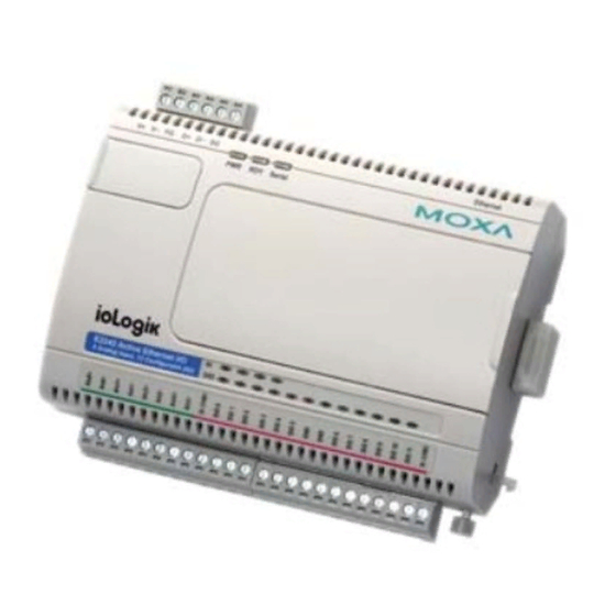
Introduction Chapter 1. The ioLogik E2242 is a stand-alone Active Ethernet I/O product with 4 analog inputs and 12 configurable DIOs. The DIN-Rail mountable E2242 allows users to connect to both digital and analog inputs, and connects digital outputs to switches, buzzers, and alarm lights, over Ethernet and IP-based networks. -
Page 7: Overview
Introduction Overview The ioLogik E2242 is a member of the E2000 line of ioLogik Active Ethernet I/O products, which are designed for intelligent, pro-active status reporting of attached sensors, transmitters, and transducers, over a network. The E2242 comes with 4 embedded analog inputs and 12 configurable DIOs of which the I/O combination is extremely flexible and suitable for various applications. -
Page 8: Click&Go
6 inputs and 6 outputs, 8 inputs and 4 outputs, or 10 inputs and 2 outputs. Digital inputs The ioLogik E2242 supports dry contact, PNP, and NPN sensors. The sensor type is determined by your wiring approach. Sensors can be wired in two different groups, so both PNP and NPN sensors can be connected to the unit at the same time. -
Page 9: Package List
Ethernet to another ioLogik E2000 series device. For typical 100 Mbps LANs, latency is only 100 ms. Power fail counter storage memory The ioLogik E2242 can store event counter values for digital inputs. Moreover, these values will not be lost during a power failure or after disconnection. New internal register and timer functions Two new Click&Go functions have been added to the ioLogik E2242. - Page 10 E2242 User’s Manual Introduction Stop Bits Flow Control None Speed 1200 to 115200 bps Protocol Modbus/RTU Analog Input Inputs 8, differential Resolution 16-bit Input Range +/-150 mV, 0 to 150mV, +/-500 mV, 0 to 500 mV, +/-5 V, 0 to...
-
Page 11: Physical Dimensions (Unit = Mm)
E2242 User’s Manual Introduction Accessories Hot-pluggable attachment for IP display, DI/DO status 16×2 character display Backlit screen 5 buttons Physical Dimensions (Unit = mm) Without LCM With LCM... -
Page 12: Hardware Reference
E2242 User’s Manual Introduction Hardware Reference Panel Guide 24 VDC power input, accepts 12 to 48 VDC RS-485 cascading interface Power, Ready, Serial LEDs Optional LCM Reset RS-485 baudrate dial RJ45 Ethernet System bus I/O module latch Release button for... -
Page 13: Led Indicators
System error (steady) ioLogik E2242 is functioning normally Ready Green (flashing) Click&Go logic is active Green & red (flashing) ioLogik E2242 is in Safe Status Serial (flashing) Serial port is receiving or transmitting data I/O LEDs Green Voltage or 0-20 mA measurement is selected... -
Page 14: Chapter 2. Initial Setup
Initial Setup Chapter 2. This chapter describes how to install the ioLogik E2242. The following topics are covered in this chapter: Hardware Installation Connecting the Power Grounding the Unit Connecting to the Network Adding More I/O Channels Setting the RS-485 Baudrate... -
Page 15: Hardware Installation
Connecting to the Network Connect the ioLogik to the host PC with an Ethernet cable. For initial configuration, it is recommended that the ioLogik E2242 to be configured using a direct connection to a host computer rather than remotely over the Internet. -
Page 16: Setting The Rs-485 Baudrate
8, and stop bit = 1. Baudrate for RS-485 Dial setting and corresponding baudrate: (parameters are N, 8, 1) 0:115200 1:57600 2:38400 3:19200 4:9600 5:4800 6:2400 7:1200 Remember to restart the ioLogik E2242 after making any changes to the RS-485 baud rate. -
Page 17: Connecting The I/O Device
Initial Setup Connecting the I/O Device With 4 channels of analog inputs and 12 configurable DIOs, the ioLogik E2242 offers great flexibility for connecting I/O devices. Also, unlike traditional Ethernet I/O products, the ioLogik E2242 can connect to analog sensors, dry contact, PNP, and NPN sensors at the same time. The... -
Page 18: Software Installation
E2242 User’s Manual Initial Setup ATTENTION When connecting the I/O device to the ioLogik’s dry contacts, we strongly recommended connecting DI.Com to the power of the external sensor to avoid affecting other channels. DI.Com input power should be limited at 12 to 36 VDC. - Page 19 E2242 User’s Manual Initial Setup NOTE: The best approach to set up a previously configured ioLogik is to reset it to the factory default using the reset button (see Chap.1). You can then use ioAdmin to configure the ioLogik.
- Page 20 E2242 User’s Manual Initial Setup Connecting Multiple ioLogik E2000 Units If multiple ioLogik E2000 units are installed on the same network, remember that each unit has the same default IP address. You will need to assign a different IP address to each unit to avoid IP conflicts.
- Page 21 E2242 User’s Manual Initial Setup Monitoring I/O status: Once your unit has been found by ioAdmin, you can view the status of all attached I/O devices on ioAdmin’s main screen. You can now use ioAdmin to setup or configure your unit. Please refer to Chapter 3 for...
-
Page 22: Chapter 3. Using Ioadmin
Using ioAdmin Chapter 3. In this chapter, we explain how to use ioAdmin to configure your ioLogik product. The following topics are covered in this chapter: Introduction to ioAdmin Features of ioAdmin ioAdmin Main Screen Main Screen Overview Wiring Guide Menu Items Main Window ioAdmin Administrator Functions... -
Page 23: Introduction To Ioadmin
E2242 User’s Manual Using ioAdmin Introduction to ioAdmin ioLogik Ethernet I/O can be managed and configured over the Ethernet with ioAdmin, a Windows utility provided with your ioLogik. ioAdmin’s graphical-user interface gives you easy access to all status information and settings. - Page 24 E2242 User’s Manual Using ioAdmin Configuration File ioAdmin allows the entire configuration of the ioLogik E2000 series to be saved as a file. The file is viewable as text and can serve three purposes: As a record or backup of configuration.
-
Page 25: Ioadmin Main Screen
E2242 User’s Manual Using ioAdmin ioAdmin Main Screen Main Screen Overview This is ioAdmin’s main screen. The main window defaults to the I/O Configuration tab, which displays a figure of your unit with the status of every I/O channel. The other tabs in the main window take you to server and network settings, and further functions are available when you log on ioLogik. -
Page 26: Wiring Guide
E2242 User’s Manual Using ioAdmin Wiring Guide ioAdmin provides a wiring guide for the ioLogik E2000 series. You can access the wiring guide by right-clicking the ioLogik figure in the I/O Configuration tab. Select “Wiring Guide” in the submenu to open a help file showing the unit’s wiring information and electrical characteristics. -
Page 27: Menu Items
E2242 User’s Manual Using ioAdmin Menu Items File From the File menu, you can export the list of the ioLogik that are currently displayed in the navigation panel. You also can import a list into ioAdmin. When importing a server list, you will be prompted to select which ioLogik on the list need to be imported. -
Page 28: System
E2242 User’s Manual Using ioAdmin System Several operations can be accessed from the System menu. Auto Scan Active Ethernet I/O Server searches for ioLogiks on the network. When connecting for the first time, or when recovering from a network disconnection, you can use this command to find any ioLogik that is connected to the physical network. -
Page 29: Help
E2242 User’s Manual Using ioAdmin Help In the Help menu, you can view wiring guides and information about ioAdmin. Quick Links Quick links are provided to search for the ioLogik on the network and sort the server list. Search network for I/O servers... -
Page 30: Server Info Tab
E2242 User’s Manual Using ioAdmin Server Info Tab Server information, such as firmware version, is displayed in the Server Info tab. Server Settings Tab (General) The Server Settings tab is where you log in as an ioAdmin administrator. This is required in order to gain access to the ioLogik configuration options. -
Page 31: Message Monitor Tab
E2242 User’s Manual Using ioAdmin Message Monitor Tab The Message Monitor tab will display any TCP/UDP Active Messages reported by the ioLogik E2000 series. When you install the unit for the first time, the ruleset will not have been defined yet, so there will be no messages in the Message Monitor Tab. -
Page 32: I/O Configuration Tab (Administrator)
Configuring Analog Input Channels The ioLogik E2242 is equipped with 4 AI (analog input) channels that can be set individually to +/-150 mV, 0 to 150mV, +/-500 mV, 0 to 500 mV, +/-5V, 0 to 5V, +/-10V, 0 to 10V, 0 to 20 mA, and 4 to 20 mA. - Page 33 E2242 User’s Manual Using ioAdmin Auto Scaling can also help to eliminate high or low end extremes. For example, if 17 mA represents a dangerous situation of high temperature, it will not be necessary to get a temperature that is even higher. In this case, users can cut off values beyond 17 mA and convert it to a proprietary level of danger, such as Level 5.
- Page 34 Power On Settings. To switch between DI and DO channel operation, select the desired mode in the I/O Direction field under Power On Settings. After clicking Apply, you will need to restart the ioLogik E2242 for the new setting to take effect. Configuring Digital Input Channels...
- Page 35 E2242 User’s Manual Using ioAdmin The ioLogik E2242 provides up to 12 digital input (DI) channels,. Software filtering is used to control switch bounces. The filter is configurable in multiples of 0.5 ms and accepts values between 1 and 65535. For example, a setting of 2 would mean a 1 ms filter (2 × 0.5 ms).
- Page 36 The Apply to all channels option applies all settings to DI channels. Configuring Digital Output Channels The ioLogik E2242 provides up to 12 digital output channels. A DO channel can be set to “DO” or “Pulse Output” mode. In DO mode, the specifications are as follows.
-
Page 37: Alias Name
E2242 User’s Manual Using ioAdmin ATTENTION The Host Connection Watchdog is disabled by default and must be enabled for Safe Status Settings to take effect. Testing DI and DO Channels You can test each channel by opening the channel’s configuration window and selecting the Test tab. -
Page 38: Server Settings Tab (Administrator)
E2242 User’s Manual Using ioAdmin Server Settings Tab (Administrator) You can set up a password, server name, location, date, time zone, and time server in the Server Settings tab. ioAdmin supports long server names and a location description up to 58 chars. If you will be using ioEventLog to receive server status reports, such as for warm or cold starts, indicate the IP address and port number for the PC that will be running ioEventLog in the “System Log”... -
Page 39: Network Tab
E2242 User’s Manual Using ioAdmin Network Tab The Network tab is available after you log in as an administrator. You can now configure IP settings, Modbus/TCP Alive Check Timeout settings, DNS settings, Serial settings, SNMP settings, and Web Access settings for the ioLogik. -
Page 40: Firmware Update Tab
E2242 User’s Manual Using ioAdmin SNMP Settings The ioLogik E2000 provides SNMP v2 (Simple Network Management Protocol) to allow monitoring of the network and I/O devices with SNMP Network Management software. It is useful for building automation and telecom applications. Use these fields to enable SNMP and set the read and write community strings. -
Page 41: Watchdog Tab
E2242 User’s Manual Using ioAdmin Watchdog Tab The Watchdog tab is available after you log in as an administrator. When enabled, the Host Connection Watchdog monitors the network connection. If the connection is lost for the specified Timeout value, the Watchdog will display a warning and activate the Safe Status settings for each DO channel and Event Counter channel. -
Page 42: Server Context Menu
E2242 User’s Manual Using ioAdmin Changes in the Click&Go Logic tab are not effective until the ioLogik E2000 series is restarted, just like changes made in other tabs. After logging back in as an administrator and returning to the Click&Go Logic tab, click Download to view the current ruleset. - Page 43 E2242 User’s Manual Using ioAdmin Connect Select this command to try connecting over the network to the selected ioLogik. Disconnect Select this command to drop the network connection with the selected ioLogik. Delete I/O Server Select this command to remove the selected ioLogik. The ioLogik must be disconnected first.
-
Page 44: Using Tftp To Import/Export Configuration
E2000 I/O servers support the use of TFTP to import or export configuration files. The following is an example using Windows TFTP and an ioLogik E2242 with an IP address of 192.168.127.254: 1. -
Page 45: Using Ioeventlog
E2242 User’s Manual Using ioAdmin ATTENTION You can also run TFTP client software, open the configuration file, and enter the remote server’s IP. Note that both ASCII and Octet mode are supported. When the download process is complete, the I/O server will reboot. WinTFTP Client Pro is a trademark of WinTFTP. All rights reserved. -
Page 46: Configuration
E2242 User’s Manual Using ioAdmin Configuration In the System menu, select Settings to configure ioEventLog. The Alarm Listen Port is the TCP port number that will be monitored for status events. You can modify this setting as necessary to receive signals through a firewall. It will need to match the settings for the ioLogik server that is being monitored. -
Page 47: Checking Connected Devices
E2242 User’s Manual Using ioAdmin Checking Connected Devices You can see which I/O servers are already connected to ioEventLog by selecting Connected Device List from the Connection menu. You will be prompted to view which devices are connected. 3-26... -
Page 48: Opening Log Files
E2242 User’s Manual Using ioAdmin Opening Log Files You can view previously saved logs by selecting Open from the Log menu. You will be prompted for the data that you wish to view. The logs for the day that you select will be displayed in the Alarm Log Viewer window. -
Page 49: Chapter 4. Web Console Configuration
Web Console Configuration Chapter 4. The ioLogik E2000 series built in web console can be used to configure many of the ioLogik’s settings. The following topics are covered: Introduction to the Web Console Basic Settings Network Settings General Settings Ethernet Configurations RS-485 Settings I/O Settings DI Channels... -
Page 50: Introduction To The Web Console
E2242 User’s Manual Web Console Configuration Introduction to the Web Console The ioLogik web console is a browser-based configuration utility. When the ioLogik is connected to your network, the server’s IP address in your web browser to access the web console. Note that although most configuration options are available in the web console, some settings are only available through ioAdmin. -
Page 51: Basic Settings
E2242 User’s Manual Web Console Configuration Basic Settings On the Basic Settings page, you can set the ioLogik’s system time or provide the IP address of a time server for time synchronization. Network Settings General Settings On the General Settings page, you can assign a server name and location to assist you in differentiating between different I/O servers and enable the Host Communication Watchdog and define the timeout value. -
Page 52: Rs-485 Settings
E2242 User’s Manual Web Console Configuration RS-485 Settings On the RS-485 Settings page, you can view the serial communication parameters, but no configuration changes are allowed. The baudrate can only be configured using the physical dial on the back of the unit. This is a reserved function. - Page 53 E2242 User’s Manual Web Console Configuration A DI channel can be set to “DI” or “Event Counter” mode. In DI mode, the specifications are as follows: Type Logic 0 Logic 1 Dry contact close to GND open Wet contact 0 to 3 V 3.5 to 30 V...
-
Page 54: Do Channels
E2242 User’s Manual Web Console Configuration DO Channels On the DO Channels page, you can view the status of each DO (digital output) channel. Only DIO channels that are acting as DO channels will be displayed. Click on a channel to see that channel’s configuration options. DO Channels can operate in DO mode or Pulse Output mode. -
Page 55: Ai Channels
E2242 User’s Manual Web Console Configuration AI Channels On the AI Channels page, you can view the status of each AI (analog input) channel. Click on a channel to see that channel’s configuration options. AO Channels can operate in different input modes, such as +/-10V, or 4-20mA. -
Page 56: Alias Name
E2242 User’s Manual Web Console Configuration Alias Name Alias Name helps users configure the alias of a DI, DO, or AI channel and define the status for logic 0/1 to be On/Off or vice versa. System Management Accessible IP Settings On the Accessible IP Settings page, you can control network access to the ioLogik by allowing only specified IP addresses. -
Page 57: Snmp Agent
E2242 User’s Manual Web Console Configuration You can add a specific address or range of addresses by using a combination of IP address and netmask, as follows: To allow access to a specific IP address Enter the IP address in the corresponding field; enter 255.255.255.255 for the netmask To allow access from hosts on a specific subnet For both the IP address and netmask, use 0 for the last digit (e.g., 192.168.1.0 and... -
Page 58: Network Connection
E2242 User’s Manual Web Console Configuration Network Connection On the Network Connection page, you can view the TCP connections from other hosts. This feature can help you manage your devices. Firmware Update On the Firmware Update page, you can load new or updated firmware onto the ioLogik. -
Page 59: Export System Config
E2242 User’s Manual Web Console Configuration Export System Config On the Export System Config page, you can save the ioLogik’s configuration into a file for backup or import into another ioLogik server. If you have installed the optional LCM, you can view the status and firmware details on the LCM page. -
Page 60: Load Factory Default
E2242 User’s Manual Web Console Configuration Load Factory Default This function will reset the ioLogik to factory default settings. All previous settings including the console password will be lost. Save/Restart If you change the configuration, do not forget to reboot the system. -
Page 61: Chapter 5. Click&Go Logic
Click&Go Logic Chapter 5. Click&Go Logic was developed by Moxa to provide an easy way to program your ioLogik E2000 series for Active Ethernet I/O operation. In this chapter, we will show you how Click&Go Logic works and how to use it to develop your Active Ethernet I/O system. The following topics are covered in this chapter: Overview Features... -
Page 62: Overview
E2242 User’s Manual Click&Go Logic Overview The ioLogik E2000 series system eliminates the need for host computers to continually poll I/O devices for status. Instead, the server itself is able to monitors the status of each I/O device and take the appropriate action when the I/O status satisfies a user-defined condition. -
Page 63: Click&Go Logic Basics
E2242 User’s Manual Click&Go Logic Click&Go Logic Basics To use Click&Go Logic, open ioAdmin and log on as an ioLogik administrator on the Server Settings tab. Once you are logged on, go to the Click&Go Logic tab. It should appear as below: Click&Go Logic Tab... -
Page 64: Defining Logic Rules
E2242 User’s Manual Click&Go Logic The configuration window is where the rule is defined. There are two types of rules that can be defined: Logic rules and peer-to-peer I/O rules. Logic rules are used for DI event-based triggers, whereas peer-to-peer I/O rules are used for mapping I/O channels between two ioLogik units. -
Page 65: More Info On Repeat Interval Vs. Edge Detection
InternalREG stands for “internal register.” This condition represents a status flag to link the status of the first logic to the second one. The InternalReg function also allows a PC to control the ioLogik E2242's local output (e.g., digital output, active message, e-mail and SNMP Trap) remotely. - Page 66 E2242 User’s Manual Click&Go Logic No Edge Detection In this scenario, the rule checks each sensor for “on” status, so edge detection is not involved. As long as the sensors remain on, the required conditions are satisfied, and the THEN actions will repeat at interval N.
- Page 67 E2242 User’s Manual Click&Go Logic Edge Detection for Two Conditions In this scenario, the rule checks DI-0 and DI-1 for a change in status and DI-2 for status only. The repeat interval will not have an effect if the AND relationship is used, because the two edge conditions can never be sustained over a length of time.
-
Page 68: Then Actions
E2242 User’s Manual Click&Go Logic THEN Actions Under the THEN column, you can specify up to 3 actions that will be performed when the conditions under the IF column are satisfied. Possible actions include changing the status of a DO channel, starting or stopping an Event Counter, or sending a message by SNMP trap, TCP, UDP, or e-mail. - Page 69 E2242 User’s Manual Click&Go Logic After clicking the memo icon, enter your desired message in the Message Content window. You can select TCP or UDP as the messaging protocol, but you must use the same protocol for all Click&Go Logic rules.
- Page 70 E2242 User’s Manual Click&Go Logic SNMP trap The SNMP trap option sends an SNMP trap to one or more IP destinations. You can select a trap number between 1 and 20. (You may need to consult with your network administrator to determine how trap numbers will be used and defined in your network.) Click the memo icon to specify up to...
- Page 71 E2242 User’s Manual Click&Go Logic E-mail The E-mail option sends a customizable e-mail to one or more e-mail addresses. Click the memo icon to configure the message and parameters. The following figures show how to set up e-mail warning using ioLogik E2000 series product.
-
Page 72: Defining Peer-To-Peer I/O Rules
E2242 User’s Manual Click&Go Logic To manually add e-mail addresses to the Available receiver(s) list, enter the Name and Mail Address and click Add. Once the address has been added to the Recipient Database, use the finger icons to move it to or from the Recipient List. -
Page 73: Configuring Input Module
IP… and enter up to five IP addresses as destinations. Each IP address should belong to an ioLogik E2242 unit that will act as an output module for peer-to-peer I/O operation. You can also set up additional peer-to-peer I/O rules in order to mirror input channels to more than five destinations. -
Page 74: Configuring Output Module
E2242 User’s Manual Click&Go Logic Only DI channels that are set to DI mode can be mirrored on the output module. Peer-to-peer I/O will not function with Event Counter channels. The ioLogik E2000 can simultaneously act as both an input module and an output module. Input module operation would be configured in one rule, and another rule would be used to configure output module operation. -
Page 75: Ruleset Management Bar
E2242 User’s Manual Click&Go Logic 3. After the ioLogik E2000 has been restarted, the ruleset must be activated. After logging into ioAdmin as an administrator, go to the Click&Go Logic tab and click Run in the Ruleset Management bar. The rules in the ruleset will now be active. -
Page 76: Active I/O Messages
Active I/O Messages In this scenario, we have a voltage sensor attached to the AI channel of the ioLogik E2242; a DO channel is connected to a switch on a generator. When the voltage of the battery is low, the ioLogik will trigger the generator to start charging the battery. - Page 77 E2242 User’s Manual Click&Go Logic 1. In ioAdmin, make sure that you have logged in on the Server Settings tab. Go to the Click&Go Logic tab. 2. Double click #0 in the Rules List. The Logic Configuration window will appear.
- Page 78 E2242 User’s Manual Click&Go Logic 10. Click OK to close the Logic Configuration window. 11. Select AI-0 as your condition in the first IF field, and set its operator to “>=”, value to “18” and the unit to “mA”.
-
Page 79: Event Report By E-Mail
A digital sensor is implemented to detect if the door is open or not. When the door has been opened for 60 seconds, the ioLogik E2242 triggers an output to a local alarm light and sends out a warning e-mail at the same time. When the door is closed again, the ioLogik will turn off the alarm light and sent out another e-mail to resolve the situation. - Page 80 E2242 User’s Manual Click&Go Logic Rule 0: IF DI-0=ON, TimerDelay-0 START with interval= 60 Rule 1: IF TimerDelay-0=TIMEOUT, THEN DO-6=ON THEN e-mail Rule 2: IF DI-0=OFF, THEN DO-6=OFF THEN TimerDelay = STOP THEN e-mail 1. In ioAdmin, make sure that you have logged in on the Server Settings tab, and then go to the Click&Go Logic tab.
- Page 81 E2242 User’s Manual Click&Go Logic 14. Click the memo button. The Mail Settings window will appear. 15. Click Keyword Lookup. In the Variable List that pops up, click <Server_time> or other system information is required, and then add a description along with these keywords.
- Page 82 E2242 User’s Manual Click&Go Logic 17. Click Save. Click OK to close the Logic Configuration window. 18. Double click #2 in the Rules List. The Logic Configuration window will appear. 19. Make sure that Enable in the upper left hand corner is checked.
-
Page 83: Remote Output Control When Click&Go Is Activated
In this case, we are monitoring the concentration of oxygen in a factory. When the concentration reaches the LOW level, the ioLogik E2242 will turn on the fan and send out a warning e-mail to the system administrator. At the same time, an alarm buzzer is also turned on. The host computer or SCADA system can use the Modbus/TCP address to silence the buzzer remotely by changing the status of the internal register from true to false. - Page 84 E2242 User’s Manual Click&Go Logic I/O Configuration: The DIO-0 is configured as a digital input and displayed as DI-0 in Click&GO settings tab. The DIO-6 is configured as a digital output and displayed as DO-6 in the Click&GO settings tab.
- Page 85 E2242 User’s Manual Click&Go Logic 6. Select DO-6 as your action in the first THEN field; set its operator value to ON. 7. Select D0-7 as your action in the second THEN field, and then set its value to ON.
-
Page 86: Peer-To-Peer I/O
Rule 0: Send I/O status to 192.168.127.3 1. In ioAdmin, make sure that you have searched for and selected the correct ioLogik E2242, at IP address 192.168.127.154. Also, make sure you are logged in on the Server Settings tab. Go to the Click&Go Logic tab. - Page 87 Rule 1: DI-1 at 192.168.127.154 mapped to DO-1 1. In ioAdmin, make sure that you have searched for and selected the correct ioLogik E2242 server, at IP address 192.168.127.3. Also, make sure you are logged in on the Server Settings tab. Go to the Click&Go Logic tab.
-
Page 88: Appendix A. Liquid Crystal Display Module (Lcm
LCM Options Display Explanation / Actions This is the default “home page” showing the IP address. Press <ioLogik E2242> the down button to view the submenus. Enter this submenu to display information about the specific server you are viewing: serial number name <ioLogik E2242>... - Page 89 E2242 User’s Manual Display Explanation / Actions Enter this submenu to display information and settings for the network: ethernet link mac address ip mode <ioLogik E2242> ip address network netmask gateway dns server-1 dns server-2 Enter this submenu to display information about the Click&Go Logic ruleset currently loaded on the ioLogik:...
-
Page 90: Appendix B. Modbus/Tcp Address Mappings
Modbus/TCP Address Mappings Appendix B. ioLogik E2242 Modbus Mapping 0xxxx Read/Write Coils (Support Functions 1, 5, 15)// DIO Channel Reference Address Data Type Description 00001 0x0000 1 bit CH0 DO Value 0: Off 1: On 00002 0x0001 1 bit CH1 DO Value 0: Off 1: On... - Page 91 E2242 User’s Manual Modbus/TCP Address Mappings 00034 0x0021 1 bit CH9 DO Safe Value 0: Off 1: On 00035 0x0022 1 bit CH10 DO Safe Value 0: Off 1: On 00036 0x0023 1 bit CH11 DO Safe Value 0: Off 1: On...
- Page 92 E2242 User’s Manual Modbus/TCP Address Mappings 00081 0x0050 1 bit CH8 DI Counter Status 0: Off 1: On 00082 0x0051 1 bit CH9 DI Counter Status 0: Off 1: On 00083 0x0052 1 bit CH10 DI Counter Status 0: Off 1: On...
- Page 93 E2242 User’s Manual Modbus/TCP Address Mappings Read : 0 : Normal 1 : Overflow Write : 0 : clear overflow status 1 : return Illegal Data Value 00100 0x0063 1 bit CH3 DI OverFlow Status Read : 0 : Normal...
- Page 94 E2242 User’s Manual Modbus/TCP Address Mappings 00111 0x006E 1 bit CH2 DI Count Trigger 00112 0x006F 1 bit CH3 DI Count Trigger 00113 0x0070 1 bit CH4 DI Count Trigger 00114 0x0071 1 bit CH5 DI Count Trigger 00115...
- Page 95 E2242 User’s Manual Modbus/TCP Address Mappings 00149 0x0094 1 bit CH4 DI set channel Power-off storage enable ON/OFF 1:ON 0:OFF 00150 0x0095 1 bit CH5 DI set channel Power-off storage enable ON/OFF 1:ON 0:OFF 00151 0x0096 1 bit CH6 DI set channel...
- Page 96 E2242 User’s Manual Modbus/TCP Address Mappings 1: OUTPUT 0: INPUT (Default: OUTPUT) 00164 0x00A3 1 bit DIO 07 1: OUTPUT 0: INPUT (Default: OUTPUT) 00165 0x00A4 1 bit DIO 08 1: OUTPUT 0: INPUT (Default: OUTPUT) 00166 0x00A5 1 bit...
-
Page 97: 1Xxxx Read Only Coils (Function 2
E2242 User’s Manual Modbus/TCP Address Mappings 1xxxx Read Only Coils (Function 2) Reference Address Data Type Description 10257 0x0100 1 bit CH0 DI Value 10258 0x0101 1 bit CH1 DI Value 10259 0x0102 1 bit CH2 DI Value 10260... - Page 98 E2242 User’s Manual Modbus/TCP Address Mappings 30024 0x0017 word CH11 DI Counter Value Lo- Word 30025 0x0018 word CH0 Read AI Value 30026 0x0019 word CH1 Read AI Value 30027 0x001A word CH2 Read AI Value 30028 0x001B word...
- Page 99 E2242 User’s Manual Modbus/TCP Address Mappings Word 10 Lo byte = ‘e’ Word 11 Hi byte = ‘r’ Word 11 Lo byte = ‘\0’ … 34102 0x1005 2 word Product serial number (decimal), last 5 digits 34103 0x1006 2 word...
-
Page 100: 4Xxxx Read/Write Registers (Functions 3, 6, 16
E2242 User’s Manual Modbus/TCP Address Mappings 4xxxx Read/Write Registers (Functions 3, 6, 16) Reference Address Data Type Description 40001 0x0000 1 word CH0 DO Pulse Output Count Value Hi-Word 40002 0x0001 1 word CH0 DO Pulse Output Count Value Lo-Word... - Page 101 E2242 User’s Manual Modbus/TCP Address Mappings 40046 0x002D 1 word CH10 DO Pulse Low Signal Width Lo- Word 40047 0x002E 1 word CH11 DO Pulse Low Signal Width Hi- Word 40048 0x002F 1 word CH11 DO Pulse Low Signal Width Lo- Word...
- Page 102 E2242 User’s Manual Modbus/TCP Address Mappings 40084 0x0053 1 word CH11 DO Mode 0: DO 1: Pulse 40085 0x0054 1 word CH0 DI Count Filter 40086 0x0055 1 word CH1 DI Count Filter 40087 0x0056 1 word CH2 DI Count Filter...
- Page 103 E2242 User’s Manual Modbus/TCP Address Mappings 40106 0x0069 1 word CH9 DI Mode 0: DI 1: Count Others : return Illegal Data Value 40107 0x006A 1 word CH10 DI Mode 0: DI 1: Count Others : return Illegal Data Value...
- Page 104 E2242 User’s Manual Modbus/TCP Address Mappings 40163 0x00A2 1 word CH10 DO set/get safe mode wordvalue 40164 0x00A3 1 word CH11 DO set/get safe mode wordvalue 40165 0x00A4 1 word CH0 DO set/get pwm start wordvalue 40166 0x00A5 1 word...
- Page 105 E2242 User’s Manual Modbus/TCP Address Mappings 40212 0x00D3 1 word CH11 DI set/get counter start word 40213 0x00D4 1 word CH0 DI set/get counter clear word 40214 0x00D5 1 word CH1 DI set/get counter clear word 40215 0x00D6 1 word...
- Page 106 E2242 User’s Manual Modbus/TCP Address Mappings 40261 0x0104 1 word CH0 DI set/get safe start word 40262 0x0105 1 word CH1 DI set/get safe start word 40263 0x0106 1 word CH2 DI set/get safe start word 40264 0x0107 1 word...
- Page 107 E2242 User’s Manual Modbus/TCP Address Mappings 40310 0x0135 1 word AI Channel 2 Scale Value Lo-Word (float) 40311 0x0136 1 word AI Channel 3 Scale Value Hi-Word (float) 40312 0x0137 1 word AI Channel 3 Scale Value Lo-Word (float)
- Page 108 E2242 User’s Manual Modbus/TCP Address Mappings 08: 0 - 5V 09: 0 -10V Others: return Illegal Data Value 40515 0x0202 1 word CH2 AI Range 00: +/-150mV 01: +/-500mV 02: +/-5V 03: +/-10V 04: 0-20mA 05: 4-20mA 06 : 0 -150mV...
- Page 109 E2242 User’s Manual Modbus/TCP Address Mappings Word 0= Sec: 00-59 Word 1= Min: 00-59 Word 2= Hour: 00-23 Word 3= Day: 01-31 Word 4= Month: 01-12 Word 5= Year: 2000-2099 44102 0x1005 1 word System Local Time zone (1 ~ 63), refer to appendix time zone code.
-
Page 110: 5Xxxx Write Registers (Function 8
E2242 User’s Manual Modbus/TCP Address Mappings 44120 0x1017 20 word SNMP Manager IP2 (Server Name or IP String) 44121 0x1018 20 word SNMP Manager IP3 (Server Name or IP String) 44122 0x1019 20 word SNMP Manager IP4 (Server Name or IP String) -
Page 111: Appendix C. Used Network Port Numbers
Used Network Port Numbers Appendix C. ioLogik E2242 Network Port Usage Port Type Usage BOOTPC DHCP Export/import file Web Server SNMP Modbus Communication 4800 Auto search 9020 Peer-to-Peer function 9000 Active Message (Default) 9000 Active Message (Default) 4040 ioEventLog... - Page 112 SNMP Agents with MIB II, Appendix D. RS-232-like Groups RFC1213 MIB II Supported SNMP Variables The following SNMP variables are built into the ioLogik firmware and are compliant with RFC1213 MIB II. System MIB Interfaces MIB IP MIB ICMP MIB SysDescr ifNumber ipForwarding...
- Page 113 E2242 User’s Manual SNMP MIBII Interfaces MIB IP MIB ICMP MIB ifInUnknownProtos ipReasmFails IcmpOutTimeExcds ifOutOctets ipFragOKs IcmpOutParmProbs ifOutUcastPkts ipFragFails IcmpOutSrcQuenchs ifOutNUcastPkts ipFragCreates IcmpOutRedirects ifOutDiscards ipAdEntAddr IcmpOutEchos ifOutErrors ipAdEntIfIndex IcmpOutEchoReps ifOutQLen ipAdEntNetMask IcmpOutTimestamps ifSpecific ipAdEntBcastAddr IcmpOutTimestampReps ipAdEntReasmMaxSize IcmpOutAddrMasks ipRouteDest IcmpOutAddrMaskReps...
- Page 114 E2242 User’s Manual SNMP MIBII UDP MIB TCP MIB SNMP MIB UdpInDatagrams tcpRtoAlgorithm snmpInPkts UdpNoPorts tcpRtoMin snmpOutPkts UdpInErrors tcpRtoMax snmpInBadVersions UdpOutDatagrams tcpMaxConn snmpInBadCommunityNames UdpLocalAddress tcpActiveOpens snmpInBadCommunityUses UdpLocalPort tcpPassiveOpens snmpInASNParseErrs tcpAttempFails snmpInTooBigs tcpEstabResets snmpInNoSuchNames Address Translation tcpCurrEstab snmpInBadValues AtIfIndex tcpInSegs...
- Page 115 E2242 User’s Manual SNMP MIBII Private MIB File and SNMP Variables Moxa also provides an SNMP to I/O MIB file that can help you monitor I/O status with SNMP software. You can find the MIB file on the Document and Software CD.
- Page 116 E2242 User’s Manual SNMP MIBII DI010-Status DI010-Filter DI010-Tigger DI010-CntStart DIO10-LowWidth DIO10-HighWidth DI011-Index DI011-Type DI011-Mode DI011-Status DI011-Filter DI011-Tigger DI011-CntStart DIO11-LowWidth DIO11-HighWidth Moxa IO MIB Moxa IO MIB AI00-Index AI02-Index AI00-Type AI02-Type AI00-Range AI02-Range AI00-Value AI02-Value AI00-Min AI02-Min AI00-Max AI02-Max AI01-Index...
-
Page 117: Appendix E. Factory Default Settings
Factory Default Settings Appendix E. The factory default settings for the ioLogik E2242 are as follows: 192.168.127.254 IP address: 255.255.255.0 Netmask: None Gateway: Disable Communication Watchdog: Modbus/TCP Alive Check: Modbus/TCP Timeout Interval: 60 sec DI0-0 to DIO-5 DI Mode: DI Safe Status: 10 ×... -
Page 118: Appendix F. Cable Wiring
Cable Wiring Appendix F. Device Wiring Diagrams Analog Input Digital Input Dry Contact DI Dry Contact Power... -
Page 119: Digital Input Wet Contact
E2242 User’s Manual Cable Wiring ATTENTION When connecting the I/O device to the ioLogik’s dry contacts, we strongly recommended connecting DI.Com to the power of the external sensor to avoid affecting other channels. Digital Input Wet Contact NPN Type Sensors Connection...
Need help?
Do you have a question about the ioLogik E2242 and is the answer not in the manual?
Questions and answers