
Related Manuals for Moxa Technologies ioLogik R1210


Summary of Contents for Moxa Technologies ioLogik R1210
- Page 1 ioLogik R1200 Series User’s Manual Edition 2.1, January 2016 www.moxa.com/product © 2016 Moxa Inc. All rights reserved.
- Page 2 ioLogik R1200 Series User’s Manual The software described in this manual is furnished under a license agreement and may be used only in accordance with the terms of that agreement. Copyright Notice © 2016 Moxa Inc. All rights reserved. Trademarks The MOXA logo is a registered trademark of Moxa Inc.
-
Page 3: Table Of Contents
Package Checklist ..........................1-2 Product Model Information ........................1-2 Ordering Information ........................1-2 Specifications ............................. 1-3 Common Specifications ........................ 1-3 ioLogik R1210 ..........................1-4 ioLogik R1212 ..........................1-4 ioLogik R1214 ..........................1-5 ioLogik R1240 ..........................1-6 ioLogik R1241 ..........................1-6 Physical Dimensions .......................... - Page 4 R1210 Modbus Mapping ........................A-2 0xxxx Read/Write Coils (Functions 1, 5, 15) ................... A-2 1xxxx Read Only Coils (Function 2) ....................A-4 3xxxx Read Only Registers (Function 4) ..................A-4 4xxxx Read/Write Registers (Functions 3, 6, 16) ................A-5 R1212 Modbus Mapping ........................A-6 0xxxx Read/Write Coils (Functions 1, 5, 15) ...................
-
Page 5: Overview
Introduction Product Features Package Checklist Product Model Information Ordering Information Specifications Common Specifications ioLogik R1210 ioLogik R1212 ioLogik R1214 ioLogik R1240 ioLogik R1241 Physical Dimensions Hardware Reference ... -
Page 6: Introduction
Contact your sales representative if any of the above items are missing or damaged. Product Model Information Ordering Information ioLogik R1210 RS-485 remote I/O, 16 DIs, -10 to 75°C operating temperature. ioLogik R1210-T RS-485 remote I/O, 16 DIs, -40 to 85°C operating temperature. -
Page 7: Specifications
ioLogik R1200 Series Overview Specifications Common Specifications Serial Communication Interface: RS-485-2w: Data+, Data-, GND (5-contact terminal block) Serial Line Protection: 15 kV ESD for all signals, Level 2 surge, EN 61000-4-5 (1 kV) Serial Communication Parameters Parity: None, Even, Odd (default = None) Data Bits: 8 Stop Bits: 1, 2 (default = 1) Baudrate: 1200 to 921.6 kbps (default = 9600) -
Page 8: Iologik R1210
R1200 Series Overview ioLogik R1210 Inputs and Outputs Digital Inputs: 16 channels Isolation: 3K VDC or 2K Vrms Digital Input Sensor Type: Wet Contact (NPN or PNP), Dry Contact I/O Mode: DI or Event Counter Dry Contact: • On: short to GND •... -
Page 9: Iologik R1214
ioLogik R1200 Series Overview ioLogik R1214 Inputs and Outputs Digital Inputs: 6 channels Relay Outputs: 6 channels Isolation: 3K VDC or 2K Vrms Digital Input Sensor Type: Wet Contact (NPN or PNP), Dry Contact I/O Mode: DI or Event Counter Dry Contact: •... -
Page 10: Iologik R1240
ioLogik R1200 Series Overview ioLogik R1240 Inputs and Outputs Analog Inputs: 8 channels Isolation: 3K VDC or 2K Vrms Analog Input Type: Differential input Resolution: 16 bits I/O Mode: Voltage / Current Input Range: 0 to 10 VDC, 0 to 20 mA, 4 to 20 mA (burn-out mode) Accuracy: ±0.1% FSR @ 25°C ±0.3% FSR @ -10 and 60°C... -
Page 11: Physical Dimensions
ioLogik R1200 Series Overview Physical Dimensions The dimensions of the ioLogik R1200 product are 27.8 x 124 x 84 mm. The connector for the two RS-485 ports is a 5-pin 3.81 terminal block (2 RS-485 ports with 1 ground pin). The power connector is on the top and the reset button is on the bottom of the product. -
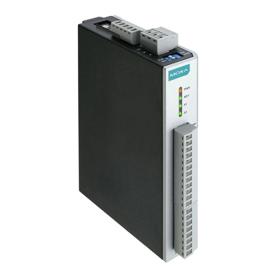
Page 12: Led Indicators
ioLogik R1200 Series Overview NOTE The RESET button restarts the server and resets all settings to factory defaults. Use a pointed object such as a straightened paper clip to hold down the reset button for 5 seconds. The factory defaults will load once the READY LED turns green again. -
Page 13: Dio Circuit Diagram
ioLogik R1200 Series Overview DIO Circuit Diagram... -
Page 14: Relay Circuit Diagram
ioLogik R1200 Series Overview Relay Circuit Diagram AI Circuit Diagram 1-10... -
Page 15: Initial Setup
Initial Setup The following topics are covered in this chapter: Hardware Installation Connecting the Power Grounding the ioLogik R1200 Mounting the ioLogik R1200 Connecting to Digital Sensors and Devices RS-485 Networks Modbus/RTU Devices ... -
Page 16: Hardware Installation
ioLogik R1200 Series Initial Setup Hardware Installation Connecting the Power Connect the 12 to 48 VDC power line to the ioLogik R1200’s terminal block on the top panel. If power is properly supplied, the Power LED will glow a solid amber color. ATTENTION Determine the maximum possible current for each power wire and common wire. -
Page 17: Connecting To Digital Sensors And Devices
ioLogik R1200 Series Initial Setup Connecting to Digital Sensors and Devices Digital Input/Output (Sink Type) A Dry Contact is a contact that does not provide voltage, e.g., the push-to-talk switch of a microphone, which just closes a circuit without providing voltage. A Wet Contact is a contact that will provide voltage when closed, e.g., a switch on the wall that activates a 110 VAC outlet to turn a lamp on in a room. -
Page 18: Rs-485 Networks
ioLogik R1200 Series Initial Setup NOTE A “load” in a circuit schematic is a component or portion of the circuit that consumes electric power. For the diagrams shown in this document, “load” refers to the devices or systems connected to the remote I/O unit. RS-485 Networks RS-485 permits a balanced transmission line to be shared in a party line or multi-drop configuration. -
Page 19: Modbus/Rtu Devices
ioLogik R1200 Series Initial Setup Modbus/RTU Devices The RS-485 port runs Modbus/RTU and can connect to any Modbus device. You may use different methods to connect different combinations of ioLogik R12000 servers and other Modbus devices. Some examples are shown below: Connecting One Modbus/RTU Device Connecting Multiple Modbus/RTU Devices Dual RS-485 or Repeater Settings... -
Page 20: Jumper Settings (Dio And Ai)
ioLogik R1200 Series Initial Setup Jumper Settings (DIO and AI) The models with DIO or AI channels require configuring the jumpers inside the cover. Remove the screw located on the back panel and open the cover to configure the jumpers. DIO mode configuration is shown to the right (default: DO Mode). -
Page 21: Software Installation
ioLogik R1200 Series Initial Setup DIP switches inside the cover of the ioLogik R1200 are used to set the pull high/low resistor values for each serial port. To set the pull high/low resistors to 150 kΩ, make sure both of the assigned DIP switches are in the OFF position (default setting). - Page 22 ioLogik R1200 Series Initial Setup • If multiple ioLogik R1200 units are installed on the same network, remember to assign a unique device ID to each unit to avoid conflicts. • If ioSearch is unable to find the ioLogik R1200 device, there may also be a problem with your COM port settings.
-
Page 23: Initial Setup By Usb
ioLogik R1200 Series Initial Setup Initial Setup by USB When setting up your ioLogik R1200 for the first time, you need to import the initial configuration and firmware files onto a USB drive. But before you connect the USB drive to the ioLogik R1200’s USB port to install and upgrade configurations and firmware, you first need to place the configuration files under a designated folder. -
Page 24: Restore Factory Default Settings
ioLogik R1200 Series Initial Setup Restore Factory Default Settings There are two ways to restore the ioLogik R1200 device to the factory default settings. 1. Hold the reset button for 5 seconds. 2. Right-click on the ioLogik unit you want to restore in the ioSearch utility and change “Reset” to “Default.” 2-10... -
Page 25: Using Iosearch
Using ioSearch The following topics are covered in this chapter: Introduction to ioSearch ioSearch Main Screen Main Screen Overview ioSearch Setup System Sort Help Quick Links Main Functions Locate Connect/Disconnect ... -
Page 26: Introduction To Iosearch
ioLogik R1200 Series Using ioSearch Introduction to ioSearch The ioSearch utility is used for locating or searching for an Logik R1200 unit on the physical network. The following functions are supported by the ioSearch utility. • Search for and locate ioLogik R1200 units •... -
Page 27: Iosearch Setup
ioLogik R1200 Series Using ioSearch ioSearch Setup System Several functions are available from the System menu. Auto Search Remote Ethernet I/O Servers will search for ioLogik servers on the network. When connecting for the first time or recovering from a network disconnection, you can use this command to find I/O servers that are on the network. - Page 28 ioLogik R1200 Series Using ioSearch Auto Search Timeout Interval: The timeout interval sets the preferred waiting time for an ioLogik R1200 device to respond to a search. After exceeding the preset time limit, ioSearch will proceed to the next device on the network.
-
Page 29: Sort
ioLogik R1200 Series Using ioSearch Once the ioLogik R1200 device has been discovered by the ioSearch utility, you will be able to monitor the I/O status from the first tab of the ioSearch utility. You will also be able to configure each DI and DO channel from this tab after first logging in under the Management tab. -
Page 30: Help
ioLogik R1200 Series Using ioSearch Help In the Help menu, you can view vendor and version information. Quick Links Quick links are provided to search for I/O servers on the RS-485 network and sort the server list. 1. Automatically searches the local network 2. -
Page 31: Firmware Upgrade
ioLogik R1200 Series Using ioSearch Firmware Upgrade The ioLogik R1200 supports a remote firmware upgrade function. Enter the path of the firmware file or click on the icon to browse for the file. The wizard will lead you through the process until the server restarts. Import Select this command to reload a configuration that was exported to a text file. -
Page 32: Restart System
ioLogik R1200 Series Using ioSearch Restart System Select this command to restart the selected ioLogik R1200 device. Restart multiple ioLogik R1200 units by right-clicking on an ioLogik R1200 and selecting this function. Delete ioLogik Device Select this function to remove an ioLogik R1200 unit from the tree manually. Reset to Default Select this function to reset all settings, including console passwords, to factory default values. -
Page 33: Main Screen
ioLogik R1200 Series Using ioSearch Main Screen I/O Configuration Tab (General) The I/O Configuration tab shows the status of every I/O channel. This is the default tab when you first open ioSearch. Configuring Digital Input Channels The ioLogik R1200’s digital channel can be separately set to “DI” or “Event Counter Mode.” In “DI” mode, the specifications are as follows: Type Logic 0 (OFF) - Page 34 ioLogik R1200 Series Using ioSearch In “Event Counter” mode, the ioLogik R1200’s DI channel accepts data from limit or proximity switches, and counts events according to the ON/OFF status. You may select from two modes, “Lo to Hi” or “Hi to Lo.” When “Lo to Hi”...
-
Page 35: Configuring Digital Output Channels
ioLogik R1200 Series Using ioSearch Configuring Digital Output Channels Each ioLogik R1200 digital output channel can be set to “DO” or “Pulse Output” mode. In DO mode, the specifications are as follows. Type Logic 0 (OFF) Logic 1 (ON) DO mode Open Short In “Pulse Output”... - Page 36 ioLogik R1200 Series Using ioSearch Power On Settings: Use this field to set the initial status for the DO channel when the ioLogik is powered on. Safe Status Settings: Use this field to specify how the DO channel responds to a break in network communication.
-
Page 37: Configuring Analog Input Channels
ioLogik R1200 Series Using ioSearch Configuring Analog Input Channels The current status of each AI (analog input) channel can be viewed on the I/O Setting: Click on a specific channel to enable or disable the AI channel by selecting the “Enable AI Channel” field. There are two modes for the AI channels: 1. -
Page 38: Configuring Analog Output Channels
ioLogik R1200 Series Using ioSearch Users can define burnout values (BO, default 2 mA) for selected ranges. When input values are in the burnout range, raw data will register as 0000h to indicate analog input burnout. The definition of raw data is as follows: Burnout Value (BO) 0.0 <... - Page 39 ioLogik R1200 Series Using ioSearch Click on a specific channel to access the AO channel settings. There are two modes for the AI channels, Voltage Mode (V) and Current Mode (mA). See Jumper Settings (DIO and AI) in Chapter 2 for more information. Power On Settings: For AO channels in Event Counter mode, you may configure whether or not counting begins at power up.
-
Page 40: Server Info Tab
ioLogik R1200 Series Using ioSearch Test I/O: You can test AO channels in the Test tab. You may see how the status or counter value responds when the attached input device is manipulated. Server Info Tab The Server Information tab provides the Modbus addresses for all system configurations. This helps you verify the access authority of each address. -
Page 41: Server Settings Tab (General)
ioLogik R1200 Series Using ioSearch Server Settings Tab (General) The Server Settings tab is where you log in as an administrator. This is required in order to gain access to the ioLogik R1200 configuration options. If no administrator password has been set up, simply click on Login and leave the Password for entry field blank. -
Page 42: Watchdog
ioLogik R1200 Series Using ioSearch Watchdog The Watchdog tab is where you configure the Host Connection Watchdog, which is used with the Safe Status settings to define each channel’s response to a lost connection. When the ioLogik R1200 loses its connection as specified in the timeout, the Host Connection Watchdog will switch the ioLogik R1200 to Safe Status and all channels will reset to their Safe Status settings. -
Page 43: Modbus Mapping
Modbus Mapping The following topics are covered in this appendix: R1210 Modbus Mapping 0xxxx Read/Write Coils (Functions 1, 5, 15) 1xxxx Read Only Coils (Function 2) 3xxxx Read Only Registers (Function 4) 4xxxx Read/Write Registers (Functions 3, 6, 16) ... -
Page 44: R1210 Modbus Mapping
ioLogik R1200 Series Modbus Mapping R1210 Modbus Mapping 0xxxx Read/Write Coils (Functions 1, 5, 15) Reference Address Data Type Description 00001 0x0000 1Bit CH0 DI Counter start, 0=OFF, 1=ON 00002 0x0001 1Bit CH1 DI Counter start, 0=OFF, 1=ON 00003 0x0002 1Bit CH2 DI Counter start, 0=OFF, 1=ON 00004... - Page 45 ioLogik R1200 Series Modbus Mapping Reference Address Data Type Description 00079 0x004E 1Bit CH14 DI Counter overflow, 0=no effect, 1=overflow 00080 0x004F 1Bit CH15 DI Counter overflow, 0=no effect, 1=overflow 00097 0x0060 1Bit CH0 DI Power on counter start, 0=OFF, 1=ON 00098 0x0061 1Bit...
-
Page 46: 1Xxxx Read Only Coils (Function 2
ioLogik R1200 Series Modbus Mapping 1xxxx Read Only Coils (Function 2) Reference Address Data Type Description 10001 0x0000 1Bit CH0 DI Bit value, 0=OFF, 1=ON 10002 0x0001 1Bit CH1 DI Bit value, 0=OFF, 1=ON 10003 0x0002 1Bit CH2 DI Bit value, 0=OFF, 1=ON 10004 0x0003 1Bit... -
Page 47: 4Xxxx Read/Write Registers (Functions 3, 6, 16
ioLogik R1200 Series Modbus Mapping Reference Address Data Type Description 30059 0x003A 2 Word CH13 DI counter value 30061 0x003C 2 Word CH14 DI counter value 30063 0x003E 2 Word CH15 DI counter value 4xxxx Read/Write Registers (Functions 3, 6, 16) Reference Address Data Type... -
Page 48: R1212 Modbus Mapping
ioLogik R1200 Series Modbus Mapping Reference Address Data Type Description 40077 0x004C 1 Word CH12 DI counter trigger type, 0:L2H, 1:H2L, 2: Both 40078 0x004D 1 Word CH13 DI counter trigger type, 0:L2H, 1:H2L, 2: Both 40079 0x004E 1 Word CH14 DI counter trigger type, 0:L2H, 1:H2L, 2: Both 40080 0x004F... - Page 49 ioLogik R1200 Series Modbus Mapping Reference Address Data Type Description 00073 0x0048 1Bit CH8 DI Counter overflow, 0=no effect, 1=overflow 00074 0x0049 1Bit CH9 DI Counter overflow, 0=no effect, 1=overflow 00075 0x004A 1Bit CH10 DI Counter overflow, 0=no effect, 1=overflow 00076 0x004B 1Bit...
- Page 50 ioLogik R1200 Series Modbus Mapping Reference Address Data Type Description 00173 0x00AC 1Bit CH12 DI power failing counter storage, 0=OFF, 1=ON 00174 0x00AD 1Bit CH13 DI power failing counter storage, 0=OFF, 1=ON 00175 0x00AE 1Bit CH14 DI power failing counter storage, 0=OFF, 1=ON 00176 0x00AF 1Bit...
-
Page 51: 1Xxxx Read Only Coils (Function 2
ioLogik R1200 Series Modbus Mapping 1xxxx Read Only Coils (Function 2) Reference Address Data Type Description 10001 0x0000 1Bit CH0 DI Bit value, 0=OFF, 1=ON 10002 0x0001 1Bit CH1 DI Bit value, 0=OFF, 1=ON 10003 0x0002 1Bit CH2 DI Bit value, 0=OFF, 1=ON 10004 0x0003 1Bit... -
Page 52: 4Xxxx Read/Write Registers (Functions 3, 6, 16
ioLogik R1200 Series Modbus Mapping Reference Address Data Type Description 30043 0x002A 2 Word CH5 DI counter value 30045 0x002C 2 Word CH6 DI counter value 30047 0x002E 2 Word CH7 DI counter value 30049 0x0030 2 Word CH8 DI counter value 30051 0x0032 2 Word... - Page 53 ioLogik R1200 Series Modbus Mapping Reference Address Data Type Description 40045 0x002C 1 Word CH12 DI filter value 40046 0x002D 1 Word CH13 DI filter value 40047 0x002E 1 Word CH14 DI filter value 40048 0x002F 1 Word CH15 DI filter value 40065 0x0040 1 Word...
-
Page 54: R1214 Modbus Mapping
ioLogik R1200 Series Modbus Mapping Reference Address Data Type Description 40481 0x01E0 1 Word CH0 DO save mode status, 0: OFF, 1: ON, 3: hold last 40482 0x01E1 1 Word CH1 DO save mode status, 0: OFF, 1: ON, 3: hold last 40483 0x01E2 1 Word... - Page 55 ioLogik R1200 Series Modbus Mapping Reference Address Data Type Description 00133 0x0084 1Bit CH4 DI Safe mode counter start, 0=OFF, 1=ON 00134 0x0085 1Bit CH5 DI Safe mode counter start, 0=OFF, 1=ON 00161 0x00A0 1Bit CH0 DI power failing counter storage, 0=OFF, 1=ON 00162 0x00A1 1Bit...
-
Page 56: 1Xxxx Read Only Coils (Function 2
ioLogik R1200 Series Modbus Mapping 1xxxx Read Only Coils (Function 2) Reference Address Data Type Description 10001 0x0000 1Bit CH0 DI Bit value, 0=OFF, 1=ON 10002 0x0001 1Bit CH1 DI Bit value, 0=OFF, 1=ON 10003 0x0002 1Bit CH2 DI Bit value, 0=OFF, 1=ON 10004 0x0003 1Bit... -
Page 57: R1240 Modbus Mapping
ioLogik R1200 Series Modbus Mapping Reference Address Data Type Description 40038 0x0025 1 Word CH5 DI filter value 40065 0x0040 1 Word CH0 DI counter trigger type, 0:L2H, 1:H2L, 2: Both 40066 0x0041 1 Word CH1 DI counter trigger type, 0:L2H, 1:H2L, 2: Both 40067 0x0042 1 Word... -
Page 58: 3Xxxx Read Only Registers (Function 4
ioLogik R1200 Series Modbus Mapping 3xxxx Read Only Registers (Function 4) Reference Address Data Type Description 30705 0x02C0 1 Word CH0 AI raw value 30706 0x02C1 1 Word CH1 AI raw value 30707 0x02C2 1 Word CH2 AI raw value 30708 0x02C3 1 Word... -
Page 59: 4Xxxx Read/Write Registers (Functions 3, 6, 16
ioLogik R1200 Series Modbus Mapping Reference Address Data Type Description 3:under-ranged 30994 0x03E1 1 Word CH1 AI status, 0: normal, 1:burnout, 2: over-ranged, 3:under-ranged 30995 0x03E2 1 Word CH2 AI status, 0: normal, 1:burnout, 2: over-ranged, 3:under-ranged 30996 0x03E3 1 Word CH3 AI status, 0: normal, 1:burnout, 2: over-ranged, 3:under-ranged 30997... -
Page 60: R1241 Modbus Mapping
ioLogik R1200 Series Modbus Mapping R1241 Modbus Mapping 4xxxx Read/Write Registers (Functions 3, 6, 16) Reference Address Data Type Description 41185 0x04A0 1 Word CH0 AO raw value (0 to 4095) 41186 0x04A1 1 Word CH1 AO raw value (0 to 4095) 41187 0x04A2 1 Word... -
Page 61: Factory Defaults
Factory Defaults The ioLogik R1200 series comes configured with the following factory default settings: Baudrate 9600 Data Bits Parity None Stop Bits Watchdog Disable Watchdog Time Out 10 seconds Server Name Blank Server Location Blank DI Mode Filter Time 100 ms Trigger for Counter Lo to Hi Counter Status... -
Page 62: Pinouts
Pinouts R1210 R1212 R1214 R1240 R1241... -
Page 63: Fcc Interference Statement
FCC Interference Statement Federal Communication Commission Warning This equipment has been tested and found to comply with the limits for a Class A digital device, pursuant to part 15 of the FCC Rules. Operation is subject to the following two conditions: (1) This device may not cause harmful interference, and (2) this device must accept any interference received, including interference that may cause undesired operation. -
Page 64: European Community (Ce
European Community (CE) This is a Class A product. In a domestic environment, this product may cause radio interference in which case the user may be required to take adequate measures.
Need help?
Do you have a question about the ioLogik R1210 and is the answer not in the manual?
Questions and answers