Table of Contents

Related Manuals for Bender ISOMETER IRDH575


Summary of Contents for Bender ISOMETER IRDH575
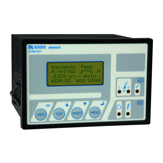
- Page 1 ISOMETER® IRDH575 Insulation monitoring device for IT AC and DC sys- tems with integrated test generator and controller for EDS46..., EDS47... and EDS49... systems Software version: D0185 V1.80 Manual EN IRDH575_D00089_05_M_XXEN/01.2020...
-
Page 2: Table Of Contents
Table of Contents 1. Important information ..................8 How to use this manual ................. 8 Technical support: service and support ........... 9 1.2.1 First level support ..................... 9 1.2.2 Repair service ..................... 9 1.2.3 Field service ..................... 10 Training courses ..................... 10 Delivery conditions .................. - Page 3 Table of Contents 3.5.5 Function input F1/F2 for connection or disconnection of IT systems being monitored ................... 22 3.5.6 ISOnet function for central control of the insulation monitoring process when several IRDH575 are interconnected in IT systems ..3.5.7 Self test ......................26 3.5.8 Relay K3: device fault alarm and EDS common message ....
- Page 4 Table of Contents 6.5.3 Changing the measuring principle from AMP to DC (Measure: AMP) ....................55 6.5.4 Setting the repetition time for automatic self tests (Autotest: 24h) ....................55 6.5.5 Setting the real-time clock (Clock) ............55 6.5.6 Setting the date (Date) ................56 6.5.7 Specifying the starting time of the automatic self test (Test) ..
- Page 5 Table of Contents 6.9.1 Bus address (Addr: ) ................... 75 6.9.2 ISO Monitor ...................... 75 6.9.3 ISOnet ........................ 76 6.9.4 Diagram COM SETUP ................... 76 6.10 PASSWORD menu ..................77 6.10.1 Activating and setting the password ............. 77 6.10.2 Diagram PASSWORD ..................77 6.11 Menu LANGUAGE ..................
- Page 6 Table of Contents 9. Technical data IRDH575 ................91 Data in tabular form ..................91 Standards, approvals and certifications ..........95 Characteristic curves ..................96 9.3.1 Characteristic curves of the ISOMETER® ..........96 9.3.2 Characteristic curves of the insulation fault locators EDS46… / EDS49…...
-
Page 7: Important Information
1. Important information 1.1 How to use this manual This manual is intended for qualified personnel working in electrical engineering and electronics! Always keep this manual within easy reach for future reference. To make it easier for you to understand and revisit certain sections in this man- ual, we have used symbols to identify important instructions and information. -
Page 8: Technical Support: Service And Support
Important information 1.2 Technical support: service and support For commissioning and troubleshooting Bender offers you: 1.2.1 First level support Technical support by phone or e-mail for all Bender products Questions concerning specific customer applications Commissioning Troubleshooting ... -
Page 9: Field Service
**Mo-Thu 7.00 a.m. - 8.00 p.m., Fr 7.00 a.m. - 13.00 p.m 1.3 Training courses Bender is happy to provide training regarding the use of test equipment. The dates of training courses and workshops can be found on the Internet at www.bender-de.com ->... -
Page 10: Inspection, Transport And Storage
Important information Sale and delivery conditions can be obtained from Bender in printed or elec- tronic format. 1.5 Inspection, transport and storage Inspect the dispatch and equipment packaging for damage, and compare the contents of the package with the delivery documents. In the event of damage in transit, please contact Bender immediately. -
Page 11: Disposal
13 August 2005 must be taken back by the manufacturer and disposed of properly. For more information on the disposal of Bender devices, refer to our homepage at www.bender-de.com -> Service & support. -
Page 12: Safety Instructions
2. Safety instructions 2.1 General safety instructions Part of the device documentation in addition to this manual is the enclosed "Safety instructions for Bender products". 2.2 Work activities on electrical installations Only qualified personnel are permitted to carry out the work necessary to install, commission and run a device or system. -
Page 13: Device-Specific Safety Information
Safety instructions 2.3 Device-specific safety information Children and unauthorised persons must not have access to or contact with the ISOMETER®. WARNING Make sure that the operating voltage is correct! Prior to insulation and voltage tests, the ISOMETER® must be disconnected from the IT system for the duration of the test. CAUTION In order to check the correct connection of the device, a functional test has to be carried out before starting the... - Page 14 Safety instructions When using ISOMETER®s in IT systems, make sure that only one active ISOMETER® is connected in each interconnected system. If IT systems are interconnected via coupling switches, make sure that ISOMETER®s not currently used are disconnected from the IT system and deactivated. IT systems coupled via diodes or capacitances may also influence the insulation monitoring process so that a central control of the different ISOMETER®s is required.
-
Page 15: Use For The Intended Purpose
Safety instructions 2.4 Use for the intended purpose The ISOMETER® is exclusively intended for: monitoring the insulation resistance of IT systems and localization of insulation faults in combination with insulation fault evaluators EDS4… In order to meet the requirements of the applicable standards, customised pa- rameter settings must be made on the equipment in order to adapt it to local equipment and operating conditions. -
Page 16: Function
Memory with real-time clock to store all alarm messages with date and time stamp RS-485 interface (BMS protocol) for data exchange with other Bender devices (RS-485 electrically isolated) Remote setting of certain parameters via the Internet (option;... -
Page 17: Essential Functions Of The Insulation Fault Location System (Eds)
(IP42) or a front-face transparent cover (IP65) are available as accessories, see page 112. The IRDH575 can be used in combination with a control and indicating device, PRC1470 version 2 or higher, for example, on the BMS (BMS = Bender Measu- ring Device Interface) bus. IRDH575_D00089_05_M_XXEN/01.2020... -
Page 18: Function
Function 3.5 Function The IRDH575 ISOMETER® is connected between the unearthed system and the protective conductor (PE). The response values and other function parameters are set via the function keys. The parameters are indicated on the LC display and are stored in a non-vola- tile memory (EEPROM) after the setting is completed. -
Page 19: Current Output For External Measuring Instrument
R1/R2 not connected + Memory: on fault memory activated R1/R2 not connected + Memory: off fault memory deactivated measuring principle "adaptive measuring pulse", a measuring principle developed by Bender. 3.5.1 Current output for external measuring instrument The current output of IRDH575 provides 0(4)…20 mA. The current output is electrically isolated from the device electronics and the RS-485 interface. -
Page 20: Interconnected Systems
Function IRDH575 via the RS-485 interface (BMS protocol) and is then indicated by an alarm LED and indicated on the display. In the Master mode (Addr. 1), this alarm message is indicated by the alarm relay K3 as common alarm. During the insulation fault location process the insulation monitoring func- tion is deactivated. -
Page 21: Function Input F1/F2 For Connection Or Disconnection Of It Systems Being Monitored
Function 3.5.5 Function input F1/F2 for connection or disconnection of IT systems being monitored The ISOMETER® can be disconnected from the IT system and set to STANDBY mode with the function input F1/F2. When the input F1/F2 is bridged, the ter- minals L1/L2 are isolated from the measuring circuit via internal coupling re- lays and terminal L3 remains connected to the measuring circuit via a resistor of 10 MΩ. - Page 22 Function BMS bus (A/B, RS485) addr. 1 addr. 2 IT system 1 IT system 2 IT system 4 IT system 3 addr. 4 addr. 3 Example: Let as assume, in the before-mentioned ring-type arrangement, the associa- ted coupling switch of the Slave ISOMETER® 2 were open. The coupling swit- ches of the BMS Master (Addr.
-
Page 23: Isonet Function For Central Control Of The Insulation Monitoring Process When Several Irdh575 Are Interconnected In It Systems
Function 3.5.6 ISOnet function for central control of the insulation monitoring process when several IRDH575 are interconnected in IT systems Up to 30 ISOMETER® can communicate with each other in an ISOnet network. The ISOnet network can only be activated when a BMS bus is used for inter- connection. - Page 24 Function Each ISOnet slave checks the network for an ISOnet master. If there is no mas- ter available, the display will show the fault message “ISOnet Master?“ after approximately 1 hour. Additionally, the LED for device errors lights and the Relay K3 switches.
-
Page 25: Self Test
Function This has the advantage that no auxiliary contacts of a coupling switch are re- quired. Furthermore, this solution is recommended for IT systems coupled via capacitances or diodes. 3.5.7 Self test In order to guarantee high functional reliability, the ISOMETER® provides com- prehensive self test functions. - Page 26 2. Press the TEST button terminals 3. Switch the supply voltage KE to earth (PE) on and off Device error x Internal device 1. Press the TEST button error 2. Switch the supply voltage on and off 3. Please contact Bender IRDH575_D00089_05_M_XXEN/01.2020...
-
Page 27: Relay K3: Device Fault Alarm And Eds Common Message
Function 3.5.8 Relay K3: device fault alarm and EDS common message Relay K3 is intended to signal device and connection errors of the ISOMETER®. In the Master mode with bus address 1, EDS alarm messages can be collectively indicated by the K3 relay as well as system fault messages. Coll- ective indication of the EDS alarms by K3 can be disabled by selecting „K3 Alarm: off“... -
Page 28: Connection
4. Connection Only qualified personnel are permitted to carry out the work necessary to install, commission and run a device or system. Risk of electrocution due to electric shock! Touching live parts of the system carries the risk of: An electric shock ... - Page 29 Connection Only one ISOMETER® may be connected to an external TEST or RESET button. The TEST and RESET inputs of different insulation monitoring devices must not be connected in parallel for collective testing. Risk of property damage due to unprofessional installation! If more than one insulation monitoring device is connected CAUTION...
- Page 30 Connection IRDH575_D00089_05_M_XXEN/01.2020...
- Page 31 Connection Legend to wiring diagram : For external indicating instrument: current output 0…20 mA or 4…20 mA External TEST button (NO contact) External RESET button (NC contact or wire jumper), (with the terminals open and the ISO-SETUP menu set to Memory: off, insulation fault alarms will not be stored).
-
Page 32: Commissioning Flow Chart
5. Commissioning flow chart 5.1 Commissioning of the ISOMETER® function range (1) IRDH575_D00089_05_M_XXEN/01.2020... - Page 33 Commissioning flow chart Commissioning of the ISOMETER® function range (2) Perform a functional test between system and earth using a suitable resistance for the mains voltage. Resistance value: 50% of the response value ALARM2. IRDH575_D00089_05_M_XXEN/01.2020...
-
Page 34: Commissioning Of The Insulation Fault Location Function (Eds)
Commissioning flow chart 5.2 Commissioning of the insulation fault location function (EDS) (1) Disconnect the electrical installation before connecting the device ! Install the respective devices of Project manual EDS470/EDS473 and the insulation fault location system manual for EDS470, DS460/490 or EDS473 EDS46x/47x and the associated measuring transformers Connect the RS485 interface of... - Page 35 Commissioning flow chart Commissioning of the insulation fault location function (EDS) (2) Shall the basic setting be Change the settings in EDS SETUP, maintained? EDS460/490 resp. EDS470 menu Carry out the test in the EDS460/490 resp. EDS470 menu Are all bus nodes available after Check the wiring and bus nodes the completion of the test ? (RS485 LED)
- Page 36 Commissioning flow chart Commissioning of the insulation fault location function (EDS) (3) Remove the resistance Alarm LEDs extinguished? Did the alarm relays respond ? Delete the alarm messages by pressing the RESET button of the EDS4... or selecting EDS RESET from the EDS460/490 menu of the IRDH575 The EDS4...
-
Page 37: Operation And Setting
6. Operation and setting 6.1 Operating features and displays IRDH575 INFO button: to query standard information/ ESC key: back (menu function), confirmation parameter change TEST button: to call up the self test (ISOMETER® only)/ Up key: parameter change, moving up in the menu RESET button: to delete insulation fault alarms (ISOMETER®... - Page 38 Operation and setting EDS LED lights: insulation fault location has been started EDS alarm LED lights: insulation fault is detected Alarm LED 1 lights: insulation fault, first warning level reached Alarm LED 2 lights: insulation fault, second warning level reached Device fault LED lights: IRDH575 defective IRDH575_D00089_05_M_XXEN/01.2020...
-
Page 39: Display In Case Of Active Eds And Detected Fault
Operation and setting 6.1.1 Display in case of active EDS and detected fault Insulation resistance is indicated in kΩ Additional information about the insulation resistance: „+“: insulation fault at L+ „–“: insulation fault at L– „s“: new measurement has started Bus address of the active EDS4…... -
Page 40: Display In The Menu Mode
Operation and setting = Polarity of the test current pulse = valid RS-485 traffic H = a new entry is made in the memory data base C = flashing, if the clock has to be set Messages: - Insulation fault - Connection system? - Connection PE? - Device error x... - Page 41 COM Setup (IRDH575 bus address) Please have the details above on hand if you have a problem and if you con- tact Bender for technical questions. Activating the TEST button starts the self test of the ISOMETER®. Pressing the RESET key resets insulation and fault messages of the ISOMETER®.
- Page 42 Operation and setting For controlling the menu system, the Up/Down keys, the ENTER key and the ESC key are used: Up key: Moving up in the menu, increasing a parameter Down key: Moving down in the menu, decreasing a parameter ENTER key: Selecting a menu item or sub menu item, confirming or sto- ring a parameter change and going back to the associated sub...
-
Page 43: Menu Structure And Menu Mode
Operation and setting 6.2 Menu structure and menu mode The presentation of the menu structure consists of two parts. One part con- sists of the menu options 1 to 8, the other one of the menu options 9 to 12. All EDS-related menu options are grouped together and are represented on one display. - Page 44 Operation and setting Changing from the menu mode to the standard mode Pressing the ESC key allows fast changing from the menu mode to the stan- dard mode. Thus, the menu item "EXIT" need not to be activated. Automatic switchover from the menu mode to the standard mode takes place when no key is pressed for approximately 5 minutes in a main or sub menu.
-
Page 45: Diagram Menu Structure
Operation and setting 6.2.1 Diagram menu structure IRDH575_D00089_05_M_XXEN/01.2020... - Page 46 Operation and setting IRDH575_D00089_05_M_XXEN/01.2020...
-
Page 47: History Info Menu
Operation and setting 6.3 HISTORY INFO menu 99 events with date and time stamp can be stored in the memory database. The database is designed as a ring memory, i.e. the eldest entry is overwritten. Data is written into a non-volatile memory and therefore provides protection against voltage failure. -
Page 48: Diagram History Info
Operation and setting 6.3.1 Diagram HISTORY INFO IRDH575_D00089_05_M_XXEN/01.2020... -
Page 49: Iso Setup Menu: Setting Of The Basic Isometer® Functions
Operation and setting 6.4 ISO SETUP menu: Setting of the basic ISOMETER® functions The response values (Alarm 1/2, prewarning and main alarm), the operating principle of the alarm relays K1 and K2 (N.O = N/O operation, N.C = N/C ope- ration), the fault storage behaviour and the selection of the current output between two different ranges are set in this menu. -
Page 50: Operating Principle Of The Alarm Relays
Operation and setting 6.4.3 Operating principle of the alarm relays K1/K2 are factory set to N.O Test, that means N/O operation. When the supple- ment "Test" has been selected, the alarm relays switch over during a manual self test. If, for any reason, the alarm relays may not switch over during a manual self test, the settings N.C or N.O are to be selected. - Page 51 Operation and setting Diagram ISO SETUP IRDH575_D00089_05_M_XXEN/01.2020...
-
Page 52: Memory Setting (On/Off)
Operation and setting K2: N.C Test = N/C operation contacts 21-22-24, with relay test (the alarm relay is energized during normal operation) K2: N.O Test = N/O operation contacts 21-22-24, with relay test (the alarm relay is deenergized during normal operation) K2 : N.C = N/C operation contacts 21-22-24, without relay test (the alarm relay is energized during normal operation) -
Page 53: Current Output For External Measuring Instruments
Operation and setting 6.4.5 Current output for external measuring instruments Factory setting: 0…20 mA The current output of the IRDH575 can be set to "0…20 mA" or "4…20 mA" via the menu point "M+/M-:". The maximum load is 500 Ω. Function 0…20 mA: Ω... -
Page 54: Iso Advanced Menu: Setting Of The Extended Functions
Operation and setting 6.5 ISO ADVANCED menu: Setting of the extended functions 6.5.1 External coupling device (AGH: no = factory setting) Coupling devices cannot be connected to the IRDH575. 6.5.2 Selecting the system leakage capacitance range This menu allows to select the maximum system leakage capacitance C max. -
Page 55: Setting The Date (Date)
Operation and setting 6.5.6 Setting the date (Date) As well as the time, the date is required for the memory, too. In the event of power supply failure, the date function is not influenced for at least 30 days. If the device is switched on again after this period, a new setting of date and time of the real-time clock is required. -
Page 56: Diagram Iso Advanced
Operation and setting 6.5.8 Diagram ISO ADVANCED IRDH575_D00089_05_M_XXEN/01.2020... -
Page 57: Eds-Setup Menu: Settings For Fault Location
Operation and setting 6.6 EDS-SETUP menu: Settings for fault location This menu allows to carry out the necessary settings for the insulation fault lo- cation system (EDS). 6.6.1 EDS auto / on / off / pos / 1cycle A selection of the start and stop conditions for EDS systems and their meaning are listed below: ... -
Page 58: Diagram Eds-Setup
Operation and setting 6.6.2 Diagram EDS-SETUP IRDH575_D00089_05_M_XXEN/01.2020... -
Page 59: System Dc / 1 Ac / 3 Ac
Operation and setting 1cycle EDS47… : As soon as the insulation resistance has fallen below the ISOMETER® response values ALARM 1 and 2, the EDS system is automatically acti- vated once. It remains active until every EDS47… has measured all channels once and as long as the test current during the measure- ments is above 1.5 mA (EDS470) or 0.15 mA (EDS473). - Page 60 Operation and setting Do not use these settings for supply voltages > 575 V. Otherwise test currents up to 7 mA can occur, which can damage sensitive equipment. 10, 25 and 50 mA for EDS470 / 460 / 490 systems, preferably 25 mA. ...
- Page 61 Operation and setting Type of sup- EDS470 EDS473 ply system min. max. min. max. 10 mA 25 mA 1 mA 2.5 mA 25 mA 25 mA 2.5 mA 2.5 mA 25 mA 25 mA 2.5 mA 2.5 mA * = Set the response value of EDS460/490 to < 5 mA (See EDS460/490 manual, Chap.
-
Page 62: K3 Alarm: On
Operation and setting 6.6.5 K3 alarm: ON The K3 relay can be used either for one or for two functions. It is always used for signalling IRDH575 device errors. K3 alarm: on = K3 signals additionally occurring EDS alarms as common alarm. Please note that this function is only active in the master mode (BMS address 1 = factory setting). -
Page 63: Channel
Operation and setting N. freq Use this menu option to select the nominal frequency of the system to be mo- nitored. You may select 50, 60 or 400 Hz. Factory setting = 50 Hz. System Use this menu option to select the type of the distribution system to be moni- tored. - Page 64 Operation and setting Diagram EDS460 /490 with General and Channel IRDH575_D00089_05_M_XXEN/01.2020...
- Page 65 Operation and setting ResVal Use this menu option to set the response values of the EDS device to be para- meterized. This applies to: EDS460 / EDS490: 2…10 mA in 1 mA steps, factory setting = 5 mA EDS461 / EDS491: 200…1000 µA in 1 µA steps, factory setting = 500 µA ...
-
Page 66: Relay
Operation and setting Op.mode Use this menu option to determine the operating mode of the 12 channel-re- lated alarm relays of an EDS490 / EDS491; Factory setting = N/O. 6.7.3 Relay Use this menu to set the parameters for common alarm and system fault alarm at the relays of EDS46…... -
Page 67: Eds Test
Operation and setting 6.7.4 EDS Test After activating this menu option, the IRDH575 checks all BMS bus nodes dis- playing the following details: Device address Device type Software version CT connection at EDS47… means: –... -
Page 68: Diagram Eds46
Operation and setting 6.7.6 Diagram EDS46… /49… with Relay, EDS-Test and EDS- Reset IRDH575_D00089_05_M_XXEN/01.2020... -
Page 69: Eds 470 Menu
Operation and setting 6.8 EDS 470 menu This menu can only be opened in the Master mode (bus address 1). When se- veral IRDH575 are interconnected via the BMS bus, all these settings can only be carried out with a Master device. 6.8.1 EDS Monitor Indication of all detected insulation faults signalled to the IRDH575 via... -
Page 70: Details About The Menu Points Relay, Memory And N-Peak
Operation and setting 6.8.4 Details about the menu points Relay, Memory and n-peak The parameters indicated on the IRDH575 display do not necessarily corres- pond to the EDS47… settings. Only when a control command is sent to EDS by pressing Return, the EDS settings of EDS47… correspond to the IRDH575 indication. -
Page 71: Diagram Eds 470
Operation and setting 6.8.5 Diagram EDS 470 IRDH575_D00089_05_M_XXEN/01.2020... -
Page 72: Relay
Operation and setting 6.8.6 Relay Operating principle of the alarm relays of EDS47…: N.C = N/C operation N.O = N/O operation = factory setting 6.8.7 Memory Setting of the memory behaviour of EDS47… The factory setting is „on“. When the memory is in "on"... -
Page 73: N-Peak
Operation and setting The CT connection monitoring of the EDS4…-12 recognizes whether a measuring current transformer is correctly connected. This will be indicated on the display after a test has been carried out as described in "Chapter 6.8.2 EDS Test". In "off position" this function is deactivated. 6.8.9 n-peak: n-peak: 1-255... -
Page 74: Com Setup Menu: Setting The Bms Interface
Operation and setting 6.9 COM SETUP menu: Setting the BMS interface 6.9.1 Bus address (Addr: ) This menu item is used to set the BMS bus address of the IRDH575. Take care that the bus address is not assigned twice. The device is factory set to address 1 and hence acts as a Master. -
Page 75: Isonet
Operation and setting 6.9.3 ISOnet Use this menu item to activate the ISOnet function of an IRDH575. Refer to page 24 for an ISOnet description. 6.9.4 Diagram COM SETUP IRDH575_D00089_05_M_XXEN/01.2020... -
Page 76: Password Menu
Operation and setting 6.10 PASSWORD menu 6.10.1 Activating and setting the password This menu can be used to activate a "Password" query. This protects the ISOMETER® against unauthorized settings and modifications. The desired password (menu item 2. Password: xxx) can be set with the UP/ DOWN keys and confirmed with the ENTER key. -
Page 77: Menu Language
Operation and setting 6.11 Menu LANGUAGE 6.11.1 Setting the national language The menu item "Language" allows fault messages of the ISOMETER® to be set to different languages. There is the choice of "German" and "English". The device menu is not influenced by the language selection. 6.11.2 Diagram Language IRDH575_D00089_05_M_XXEN/01.2020... -
Page 78: Menu Service
Operation and setting 6.12 Menu SERVICE This menu item is provided for the Bender service personnel and is protected by a password against erroneous settings. It is intended to provide fast fault clearance by qualified experts in the event of a device error. -
Page 79: Serial Interfaces
7. Serial interfaces 7.1 RS-485 interface with BMS protocol The RS-485 interface is galvanically isolated from the device electronics and current output serves as a physical transmission medium for the BMS proto- col. If several IRDH575 or other bus-capable devices are interconnected in a network via the BMS bus, the BMS bus must be terminated at both ends with a 120 Ω... -
Page 80: Topology Rs-485 Network
(e.g. J-Y(St)Y 2x0.6), screen on one side connected to earth (PE). Connection to the terminals A and B. The number of bus nodes is restricted to 32 devices. When more devices are to be connected, Bender recommends to use an RS-485 repeater DI1. IRDH575_D00089_05_M_XXEN/01.2020... -
Page 81: Bms Protocol (Bms)
Serial interfaces 7.3 BMS protocol (BMS) This protocol is an essential part of the Bender Measuring Device Interface. Data transmission generally makes use of ASCII characters. Interface data are: Baud rate: 9600 baud Transmission: 1 start bit, 7 data bits, 1 parity bit, 1 stop bit (1, 7, ... -
Page 82: Bms-Slave
Serial interfaces Master receives no answer from five subsequent addresses, the scanning cyc- le is started again. If the Master recognizes incorrect answers from a slave, the fault message "Fault RS485" is issued by the Master. Faults may be caused when: Addresses are assigned twice ... -
Page 83: Bms Operation In The Standby Mode
Serial interfaces If no flashing point appears, it may be attributed to the following: No Master available in the network More than one Master available in the network RS-485 interface (terminal A/B) not connected or reversed ... - Page 84 Serial interfaces The following table gives an overview about essential alarm messages and the assignment of the messages indicated on the display or operator panels, e.g. PRC1470. Message Channel Meaning Insulation Fault Insulation resistance < setting Alarm 1 Insulation Fault Insulation resistance <...
-
Page 85: Combination With Eds46
Serial interfaces 7.3.4 Combination with EDS46… devices The following illustration shows an IRDH575 device in combination with EDS46… and the measuring current transformers W…for insulation fault lo- cation.The factory setting of the devices can usually be maintained. If several EDS46… are used, the addresses within the range 2 to 30 in subsequent order must be used. -
Page 86: Commissioning Of An Rs-485 Network With Bms Protocol
Serial interfaces The following operating manuals are available when using the IRDH575 in combination with EDS systems for other applications: Manual for EDS470 application: power supply systems, extended systems, systems with frequency con- verters, response sensitivity of at least 5 mA Manual for EDS473 application: ... - Page 87 Serial interfaces BMS bus address ranges Addresses* Device Meaning There is no device with address 0 ! Information sent to BMS address 0 applies to all devices connected to the BMS bus (broadcast) PRC1470 Control and indicating device … IRDH275B Insulation monitoring device /375B/575 …...
-
Page 88: Factory Settings
8. Factory settings Menu Submenu Setting 1. EXIT 2. HISTORY INFO 3. ISO SETUP 1. Exit 2. Alarm1: 40 kΩ 3. Alarm2: 10 kΩ 4. K1: N.O Test 5. K2: N.O Test ---------- N.C fixed setting 7. Memory: 8. M+/M-: 0-20 mA 4. - Page 89 2. Password: 3. Status: 10. LANGUAGE 1. Exit 2. Text: German 9. SERVICE (Access only for Bender service personnel) Please check if the basic setting of the ISOMETER® complies with the require- ments of the system to be monitored. IRDH575_D00089_05_M_XXEN/01.2020...
-
Page 90: Technical Data Irdh575
9. Technical data IRDH575 9.1 Data in tabular form The values marked with * are absolute values Insulation coordination acc. to IEC 60664-1 Rated voltage..............................AC 800 V Rated impulse voltage/pollution degree......................8 kV/3 Voltage ranges IRDH575B1-4235: Nominal voltage range U ......................AC, 3NAC 20…150 V* Nominal frequency f .......................... - Page 91 Technical data IRDH575 Relative uncertainty (1 kΩ…20 kΩ) ......................+2 kΩ/+20 % Relative uncertainty (1 MΩ…10 MΩ) ....................0.2 MΩ/+20 % Measuring time......................... see characteristic curves Hysteresis (1 kΩ…10 kΩ)........................... +2 kΩ Hysteresis (10 kΩ…10 MΩ)..........................25 % Measuring circuit for insulation measurement Measuring voltage U ............................
- Page 92 Technical data IRDH575 Serial interface Interface/protocol ............................RS-485/BMS Cable length ..............................≤ 1,200 m Recommended cable (screened, screen on one side connected to PE)..........J-Y(St)Y 2x0,6 Terminating resistor..........................120 Ω (0,5 W) Switching elements Switching components............... 3 changeover contacts: K1 (Alarm 1), K2 (Alarm2), ......................
- Page 93 Technical data IRDH575 Conductor sizes (AWG)............................24…12 Degree of Protection, internal components (DIN EN 60529) .................. IP30 Degree of Protection, terminals (DIN EN 60529)..................... IP20 Degree of Protection, in case of door mounting (DIN EN 60529) ................IP40 Degree of Protection, in case of mounting into a door with panel sealing (DIN EN 60529)........IP42 Type of enclosure: suitable for panel mounting ................
-
Page 94: Standards, Approvals And Certifications
Technical data IRDH575 9.2 Standards, approvals and certifications The ISOMETER® was designed under consideration of the following standards: - DIN EN 61557-8 (VDE 0413-8): 2015-12 - DIN EN 61557-8 Ber 1 (VDE 0413-8 Ber 1): 2016-12 - IEC 61557-8: 2014 - IEC 61557-8: 2014/COR1: 2016 - DIN EN 61557-9 (VDE 0413-9): 2015-10 - IEC 61557-9: 2014... -
Page 95: Characteristic Curves
Technical data IRDH575 9.3 Characteristic curves 9.3.1 Characteristic curves of the ISOMETER® ISOMETER® response times in relation to system leakage capaci- tances of: = 1…500 µF = 20…575 V (Version B1) / 50 Hz = 340…760 V (Version B2) / 50 Hz 1000 ≤... - Page 96 Technical data IRDH575 Max. AC voltage between system and earth in the frequency range < 50 Hz IRDH575_D00089_05_M_XXEN/01.2020...
- Page 97 Technical data IRDH575 Current output 0…20 mA Ω Ω Insulation fault in kΩ Current output in mA IRDH575_D00089_05_M_XXEN/01.2020...
- Page 98 Technical data IRDH575 Current output 4…20 mA Ω Ω Insulation fault in kΩ Current output in mA IRDH575_D00089_05_M_XXEN/01.2020...
-
Page 99: Characteristic Curves Of The Insulation Fault Locators Eds46
Technical data IRDH575 9.3.2 Characteristic curves of the insulation fault locators EDS46… /EDS49… Allowable response values for AC systems Ω] 2 mA 5 mA 10 mA Allowable response values for 3AC systems Ω] 2 mA 5 mA 10 mA IRDH575_D00089_05_M_XXEN/01.2020... - Page 100 Technical data IRDH575 Allowable response values for DC systems [k Ω] 2 mA 5 mA 10 mA IRDH575_D00089_05_M_XXEN/01.2020...
-
Page 101: Characteristic Curves For The Insulation Fault Location System
Technical data IRDH575 9.3.3 Characteristic curves for the insulation fault location system EDS470 Allowable response values Curve 1a: Allowable response values in relation to the system voltage to be monitored for a maximum system leakage capacitance C as shown by curve 2a In order to start automatic insulation fault location, the resistance values to be selected for ALARM 1 and ALARM 2 must be sufficiently low at a given nominal voltage. - Page 102 Technical data IRDH575 Curve 1b: Allowable response values in relation to the system voltage to be monitored for a maximum system leakage capacitance C as shown in curve 2b. IRDH575_D00089_05_M_XXEN/01.2020...
- Page 103 Technical data IRDH575 Maximum system leakage capacitances for the insulation fault lo- cation system EDS470 Curve 2a: Maximum allowable system leakage capacitance in relation to the system vol- tage to be monitored. Up to this limiting value of the system leakage capaci- tance, the EDS system has the sensitivity illustrated in curve 1a.
- Page 104 Technical data IRDH575 Curve 3: A reduction of the response sensitivity at system leakage capacitances greater than the maximum permissible value of C taken from the curves 2a and 2b. The indication of the test current on the IRDH575 display in case of high sys- tem leakage capacitance also changes.
- Page 105 Technical data IRDH575 Limiting values for the insulation fault location system EDS473 In order to start automatic insulation fault location, the resistance values set for ALARM 1 and ALARM 2 at a given nominal voltage must not be too high. Otherwise, the EDS test current will not be sufficient for the detection of the insulation fault.
- Page 106 Technical data IRDH575 Maximum system leakage capacitances for the insulation fault lo- cation system EDS473 Curve 5: Maximum allowable system leakage capacitance in relation to the system vol- tage to be monitored. DC: the test current is to be set to 1 or 2.5. AC: the test current is to be set to 2.5 mA.
- Page 107 Technical data IRDH575 max [P F] Curve 6: When the system leakage capacitances are greater than the maximum per- missible value for C , as shown in curve 5, the response sensitivity decreases. The indication of the test current on the IRDH575 display in case of high sys- tem leakage capacitance also changes.
- Page 108 Technical data IRDH575 Status number IRDH575_D00089_05_M_XXEN/01.2020...
- Page 109 Technical data IRDH575 Dimension diagram enclosure IRDH575 All dimensions in mm Panel cut out 138 x 90 mm IRDH575_D00089_05_M_XXEN/01.2020...
-
Page 110: Ordering Details
Technical data IRDH575 9.4 Ordering details 9.4.1 Standard version Nominal volt. Supply volt. Type Art. No. IRDH575B1-427 AC 20…575 V B91065502 DC 20…575 V DC 19.2…72 V IRDH575B1-435 AC 20…575 V AC 88…264 V B91065500 DC 20…575 V DC 77…286 V IRDH575B1-4227 AC 20…150 V B91065505... -
Page 111: Protection Against Dust And Moisture
Technical data IRDH575 9.4.2 Protection against dust and moisture Type Dimensions Art. No. Panel sealing, degree of 144 x 96 mm B98060006 protection IP42 Transparent cover, degree of protection 144 x 96 mm B98060007 IP65 9.4.3 Adaptor for rail mounting The following adaptor allows fast mounting of the IRDH575 on a DIN rail according to IEC 60715. - Page 112 Technical data IRDH575 IRDH575_D00089_05_M_XXEN/01.2020...
- Page 113 INDEX - Allowable system leakage capacitance in relation to the system Alarm LED 1 39 voltage 104 Alarm LED 2 39 - Reduction of the response sensitivity Alarm messages 85 in relation to Cemax 105 Alarm relays, operating principle setting 51 Characteristic curves, EDS473 Automatic self test, repetition time 55 - Allowable response values insulation...
- Page 114 alarm 2 (Relay/op.mode) 67 - Setting the response delay, T(on) 66 Dimension diagram enclosure 110 - Setting the system coupling (DC/1 Display in the menu mode 41 AC/3 AC) 64 - Starting the EDS with IRDH575 or EDS4... continuous EDS mode (Trigger) 63 - Common message 28 - To enable or disable the CT monito- - Max.
- Page 115 How to use this manual 8 Operating features and displays IRDH575 Option "W" 17 INFO button 38 Insulation fault evaluator (EDS) 18 Insulation fault location 18 Parameter setting via Internet 79 Interconnected systems 21 Product description 18 ISO Monitor 75 ISOnet function Real-time clock 20 - activate, deactivate 76...
- Page 116 EDS470 102 - of the insulation fault evaluator EDS473 106 - see characteristic curves 96 Standards 95 Status number 109 Support 9 System leakage capacity, adaptation 55 Technical data 91 Terminating resistor 80 TEST button 38 Test current 20 Test of all bus nodes, EDS test 68 Topology RS-485 81 Training courses 10 Wiring 81...
Need help?
Do you have a question about the ISOMETER IRDH575 and is the answer not in the manual?
Questions and answers