Table of Contents
Advertisement
Quick Links
Manual
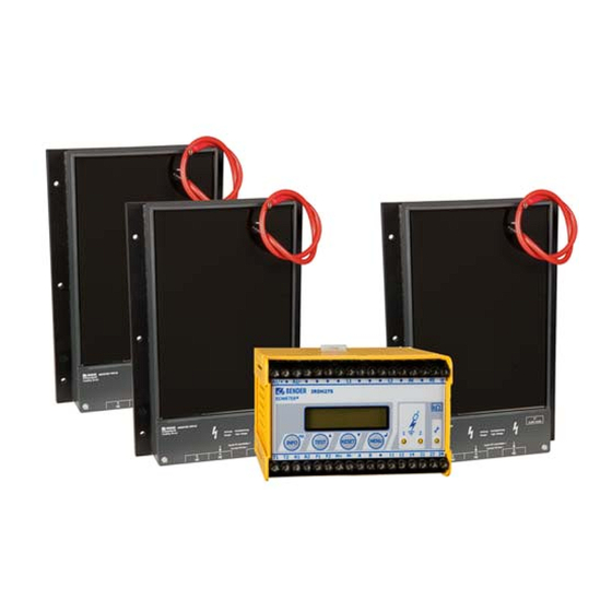
ISOMETER® IRDH275BM-7
Coupling device AGH675S-7
and AGH675S-7MV15
Insulation monitoring device for medium voltage
IT systems with galvanically connected rectifiers
and converters up to AC/DC 15.5 kV in combination with
the coupling devices AGH675S-7 and AGH675S-7MV15
IRDH275BM-7_D00123_06_M_XXEN/07.2018
Advertisement
Table of Contents

Related Manuals for Bender AGH675S-7


Summary of Contents for Bender AGH675S-7
- Page 1 Manual ISOMETER® IRDH275BM-7 Coupling device AGH675S-7 and AGH675S-7MV15 Insulation monitoring device for medium voltage IT systems with galvanically connected rectifiers and converters up to AC/DC 15.5 kV in combination with the coupling devices AGH675S-7 and AGH675S-7MV15 IRDH275BM-7_D00123_06_M_XXEN/07.2018...
- Page 2 P.O. Box 1161 • 35301 Grünberg • Germany Tel.: +49 6401 807-0 Fax: +49 6401 807-259 E-mail: info@bender.de Web: http://www.bender.de © Bender GmbH & Co. KG All rights reserved. Reprinting only with permission of the publisher. Subject to change! Photos: Bender archives and bendersystembau archives.
-
Page 3: Table Of Contents
Directions for installation ................16 3. Function ......................18 Characteristics IRDH275BM-7 incl. AGH675S-7… ......18 Product description ..................19 Function ......................19 4. Installation and connection ................. 24 Installation of the coupling device AGH675S-7… ......24 Wiring diagram ....................25 IRDH275BM-7_D00123_06_M_XXEN/07.2018... - Page 4 Table of Contents 5. Operation and setting .................. 30 Operating features and displays IRDH275BM-7 ......... 30 5.1.1 Display in the standard mode ..............31 5.1.2 Display in the menu mode ................. 31 5.1.3 Function keys ....................32 Menu structure and menu mode ............34 5.2.1 Diagram menu structure ................
- Page 5 6.3.1 BMS Master ...................... 53 6.3.2 BMS Slave ......................54 6.3.3 Commissioning of an RS-485 network with BMS protocol .... 55 7. Technical data IRDH275BM-7 with AGH675S-7… ........57 Data in tabular IRDH275BM-7 ..............57 Standards and approvals ................60 Data in tabular AGH675S-7 ................
- Page 6 Table of Contents IRDH275BM-7_D00123_06_M_XXEN/07.2018...
-
Page 7: Important Information
1. Important information 1.1 How to use this manual This manual is intended for qualified personnel working in electrical engineering and electronics! Always keep this manual within easy reach for future reference. To make it easier for you to understand and revisit certain sections in this man- ual, we have used symbols to identify important instructions and information. -
Page 8: Technical Support: Service And Support
Important information 1.2 Technical support: service and support For commissioning and troubleshooting Bender offers you: 1.2.1 First level support Technical support by phone or e-mail for all Bender products Questions concerning specific customer applications Commissioning Troubleshooting ... -
Page 9: Field Service
ZVEI (Zentralverband Elektrotechnik- und Elektronikindustrie e. V.) (German Electrical and Electron- ic Manufacturer's Association) also applies. Sale and delivery conditions can be obtained from Bender in printed or elec- tronic format. IRDH275BM-7_D00123_06_M_XXEN/07.2018... -
Page 10: Inspection, Transport And Storage
Inspect the dispatch and equipment packaging for damage, and compare the contents of the package with the delivery documents. In the event of damage in transit, please contact Bender immediately. The devices must only be stored in areas where they are protected from dust, damp, and spray and dripping water, and in which the specified storage tem- peratures can be ensured. -
Page 11: Disposal
13 August 2005 must be taken back by the manufacturer and disposed of properly. For more information on the disposal of Bender devices, refer to our homepage at www.bender-de.com -> Service & support. -
Page 12: Safety Instructions
2. Safety instructions 2.1 General safety instructions Part of the device documentation in addition to this manual is the enclosed "Safety instructions for Bender products". 2.2 Work activities on electrical installations Only qualified personnel are permitted to carry out the work necessary to install, commission and run a device or system. -
Page 13: Device-Specific Safety Information
Safety instructions 2.3 Device-specific safety information Children and unauthorised persons must not have access to or contact with the ISOMETER®. WARNING Make sure that the operating voltage is correct! Prior to insulation and voltage tests, the ISOMETER® must be disconnected from the IT system for the duration of the test. CAUTION In order to check the correct connection of the device, a functional test has to be carried out before starting the... - Page 14 Safety instructions When using ISOMETER®s in IT systems, make sure that only one active ISOMETER® is connected in each interconnected system. If IT systems are interconnected via coupling switches, make sure that ISOMETER®s not currently used are disconnected from the IT system and deactivated. IT systems coupled via diodes or capacitances may also influence the insulation monitoring process so that a central control of the different ISOMETER®s is required.
-
Page 15: Intended Use
Safety instructions 2.4 Intended use The ISOMETER® with additional coupling devices is intended for: monitoring the insulation resistance of IT systems. In order to meet the requirements of the applicable standards, customised pa- rameter settings must be made on the equipment in order to adapt it to local equipment and operating conditions. -
Page 16: Directions For Installation
Safety instructions 2.5 Directions for installation Risk of property damage due to unprofessional installation! If more than one insulation monitoring device is connected CAUTION to a conductively connected system, the system can be damaged. If several devices are connected, the device does not function and does not signal insulation faults. - Page 17 Safety instructions IThe devices, variant -7.. are delivered with the following factory setting: ISO SETUP Alarm 1 / Alarm 2 = 2 MΩ / 100 kΩ (response values) ISO SETUP Operating principle K1/K2 = N/O operation ISO SETUP Memory = off = 2 µF System leakage capacitance ADVAN-...
-
Page 18: Function
Memory with real-time clock to store all alarm messages with date and time stamp. BMS interface (BMS protocol) for data exchange with other Bender devices (RS-485 electrically isolated). Current output 0 (4)…20mA (galvanically separated) in relation to the ... -
Page 19: Product Description
The device automatically adapts itself to the existing system leakage capaci- tance. The IRDH275BM-7 can be used in combination with a control and indi- cation panel, e.g. PRC1470 version 2 or higher, on the BMS (BMS = Bender Measuring Device Interface) bus. - Page 20 The connections for an external kΩ display supplied by the current output 0(4)…20 mA at M+/M- are galvanically isolated. measuring principle "adaptive measuring pulse", a measuring principle developed by Bender (European Patent: EP 0 654 673 B1). IRDH275BM-7_D00123_06_M_XXEN/07.2018...
- Page 21 Function Self test A self test can be carried out manually using the TEST button or automatically. In order to guarantee high functional reliability, the ISOMETER® IRDH275BM- 7 provides comprehensive self test functions. After switching the supply volt- age on, all internal measuring functions, the components of the process con- trol such as data and parameter memory as well as the earth connections are checked using the self test functions.
- Page 22 1. Press TEST button 2. Switch the supply voltage off and on 3. Contact Bender If the on/off switching of the supply voltage is not possible for technical reasons, a RESET of the process control can be carried out by pressing the "ESC“, "RESET“ and "MENU“ key.
- Page 23 Function Function input F1/F2 to switch over to the standby mode When the input terminals F1/F2 are bridged, the measuring function is stopped and the message "STANDBY" appears on the display. The currently measured value is blanked and the value > 10 MΩ is indicated. The alarm re- lays and alarm LEDs no longer provide alarm messages.
-
Page 24: Installation And Connection
4. Installation and connection 4.1 Installation of the coupling device AGH675S-7… Danger of electric shock! The coupling device is operated with voltages above 1000 V, which can be life-threatening in case of direct contact. Make DANGER sure that only electrically skilled persons work on or with the device. -
Page 25: Wiring Diagram
Installation and connection 4.2 Wiring diagram Connect the terminals A1/+ and A2/- to the supply voltage U in accordance with IEC 60364-4-43. The connections to the supply voltage shall be provided with protective devices to afford protection in the event of a short circuit (a 6 A fuse is recommended). - Page 26 Installation and connection Wiring diagram AGH675S-7 IRDH275BM-7_D00123_06_M_XXEN/07.2018...
- Page 27 Installation and connection Wiring diagram AGH675S-7MV15 DC 15,5 kV 15,5 kV AC/DC 15,5 kV AC/DC AGH675S-7MV15 AGH675S-7MV15 IRDH275BM-7_D00123_06_M_XXEN/07.2018...
- Page 28 5: 200 V Separate connection of and KE to PE Separate connection of the terminals 3 and 4 of the AGH675S-7 or AGH675S-7MV15 to PE External TEST button (NO contact) External RESET button (NC contact or wire jumper),...
- Page 29 Installation and connection The wiring diagram before is to be taken by way of example. IRDH275BM-7_D00123_06_M_XXEN/07.2018...
-
Page 30: Operation And Setting
5. Operation and setting 5.1 Operating features and displays IRDH275BM-7 1 INFO key: to query standard information / ESC key: back to the menu function, confirmation parameter change 2 TEST button: to call up the self test/ Up key: parameter change, moving up in the menu 3 RESET button: to delete insulation fault alarms Down key: parameter change, moving down in the menu 4 MENU key: to activate the menu system / Enter key: confirmation para-... -
Page 31: Display In The Standard Mode
Operation and setting 5.1.1 Display in the standard mode 1 Indication of the insulation resistance in kΩ 2 Additional information about the insulation resistance: "+" = insulation fault at L+ "–" = insulation fault at L– "s" = new measurement has started = polarity of the measuring pulse = valid bus communication signals H = new entry in the memory data base... -
Page 32: Function Keys
COM-Setup (own bus address) Please have the details above on hand if you have a prob- lem and if you contact Bender for technical questions. Activating the TEST button starts the ISOMETER® self test. Pressing the RESET button resets insula- tion and fault alarm messages stored in the ISOMETER®. - Page 33 Operation and setting For controlling the menu system, the arrow keys, the ENTER key and the ESC key are used: Arrow up key: Moving up in the menu, increasing a parameter Arrow down key: Moving down in the menu, reducing a parameter ENTER key Selecting a menu item or sub menu item, confirming or stor- ing a parameter change and going back to the associated sub...
-
Page 34: Menu Structure And Menu Mode
Operation and setting 5.2 Menu structure and menu mode Switchover to the menu mode After pressing the MENU key, you can change from the standard mode to the menu mode. From the menu mode you can link to the different sub menus. Navigation within the menu Select the desired menu item using the UP/DOWN keys. -
Page 35: Diagram Menu Structure
Operation and setting 5.2.1 Diagram menu structure IRDH275BM-7_D00123_06_M_XXEN/07.2018... -
Page 36: Menu History Info
Operation and setting 5.3 Menu HISTORY INFO 99 events with date and time stamp can be stored in the memory database. The database is designed as a ring memory, i.e. the eldest entry is overwritten. Data is written into a non-volatile memory and therefore provides protection against voltage failure. -
Page 37: Diagram History Info
Operation and setting 5.3.1 Diagram HISTORY INFO IRDH275BM-7_D00123_06_M_XXEN/07.2018... -
Page 38: Menu Iso Setup: Setting Of The Basic Isometer® Functions
Operation and setting 5.4 Menu ISO SETUP: Setting of the basic ISOMETER® functions All alarm functions such as Alarm 1 and Alarm 2 (prewarning and main alarm), the operating principle of the alarm relays K1 and K2 (N.O = N/O operation, N.C = N/C operation), the fault storage behaviour and a selection of two cur- rent output ranges are set in this menu. -
Page 39: Operating Principle Of The Alarm Relays
Operation and setting 5.4.2 Operating principle of the alarm relays K1/K2 are factory set to N.O Test, that means N/O operation. When the supple- ment "Test" has been selected, the alarm relays switch over during a manual self test. If, for any reason, the alarm relays may not switch over during a manual self test, the settings N.C or N.O are to be selected. - Page 40 Operation and setting Diagram ISO SETUP IRDH275BM-7_D00123_06_M_XXEN/07.2018...
-
Page 41: Memory Setting (On/Off)
Operation and setting During the automatic self test, the alarm relays are not switched over. When a system fault occurs at the ISOMETER®, the relay K2 will automatically be activated as a system fault relay. 5.4.3 Memory setting (on/off) Memory: on = Fault memory is activated The device must be reset with the RESET button after clearing the fault. -
Page 42: Menu Iso Advanced: Setting Of The Extended Functions
5.5.1 Coupling devices AGH: 675S-7… The ISOMETER® is connected to the AGH675S-7 by connecting the terminal AK to terminal 5. The nominal operating range is extended to AC 0…7.2 kV (AGH475S-7) or AC 0…15.5 kV (two AGH475S-7MV). When terminal 2 will be connected to the midpoint of the DC intermediate circuit, a voltage of 14.4 kV... -
Page 43: Setting The Date (Date)
Operation and setting 5.5.6 Setting the date (Date) As well as the time, the date is required for the memory, too. In the event of power supply failure, the date function is not influenced for at least 30 days. If the device is switched on again after this period, a new setting of date and time of the real-time clock is required. -
Page 44: Diagram Iso Advanced
Operation and setting 5.5.8 Diagram ISO ADVANCED IRDH275BM-7_D00123_06_M_XXEN/07.2018... -
Page 45: Menu Com Setup: Setting The Bms Interface
Operation and setting 5.6 Menu COM SETUP: Setting the BMS interface 5.6.1 Bus address „Addr:“ This menu item is used to set the BMS bus address of the ISOMETER®. Since there are several ISOMETERs in one system, take care that the bus address is not assigned twice. -
Page 46: Diagram Com Setup
Operation and setting 5.6.2 Diagram COM SETUP IRDH275BM-7_D00123_06_M_XXEN/07.2018... -
Page 47: Menu Password
Operation and setting 5.7 Menu PASSWORD 5.7.1 Activating and setting the password This menu can be used to activate a "Password" query. This protects the ISOMETER® against unauthorized settings and modifications. The desired password (menu item 2. Password: xxx) can be set with the UP/DOWN keys and confirmed with the ENTER key. -
Page 48: Diagram Password
Operation and setting 5.7.2 Diagram PASSWORD IRDH275BM-7_D00123_06_M_XXEN/07.2018... -
Page 49: Menu Language
Operation and setting 5.8 Menu LANGUAGE 5.8.1 Setting the national language The menu item "Language" allows fault messages of the ISOMETER® to be set to different languages. There is the choice of German and English. The device menu is not influenced by the language selection. 5.8.2 Diagram Language IRDH275BM-7_D00123_06_M_XXEN/07.2018... -
Page 50: Menu Service
Operation and setting 5.9 Menu SERVICE This menu item is provided for the Bender service personnel and is protected by a password against erroneous settings. It is intended to provide fast fault clearance by qualified experts in the event of a device error. -
Page 51: Serial Interfaces
6. Serial interfaces 6.1 RS-485 interface with BMS protocol The RS-485 interface which is galvanically isolated from the device electronics and current output serves as a physical transmission medium for the BMS pro- tocol. If several ISOMETER®s or other bus-capable devices are interconnected in a network via the BMS bus, the BMS bus must be terminated at both ends with a 120 Ω... -
Page 52: Topology Rs-485 Network
(e.g. J-Y(ST)Y 2x0.6), screen on one side connected to earth (PE). Connection to the terminals A and B. The number of bus nodes is restricted to 32 devices. When more devices are to be connected, Bender recommends to use an RS-485 repeater DI1. IRDH275BM-7_D00123_06_M_XXEN/07.2018... -
Page 53: Bms Protocol
Serial interfaces 6.3 BMS protocol This protocol is an essential part of the Bender Measuring Device Interface. Data transmission generally makes use of ASCII characters. Interface data are: Baud rate: 9600 baud transmission: 1 start bit, 7 data bits, 1 parity bit, 1 stop bit (1, 7, E, 1) ... -
Page 54: Bms Slave
Serial interfaces Faults may be caused when: addresses are assigned twice a second master exists on the BMS bus interference signals occur on the bus lines a defective device is connected to the bus ... -
Page 55: Commissioning Of An Rs-485 Network With Bms Protocol
Serial interfaces The following table gives an overview about essential alarm messages and the assignment of the messages indicated on the display or operator panels, e.g. PRC1470. Message Channel Meaning Insulation Insulation resistance < setting Alarm 1 Fault Insulation Insulation resistance < setting Alarm 2 Fault Connection PE Connection error... - Page 56 Serial interfaces BMS-bus address ranges Addresses* Device Meaning There is no device with address 0 ! Information sent to address 0 applies to all devices connected to the interface (broadcast) PRC1470 Control and indicating device 1…30 IRDH275B/ Insulation monitoring device 375B/575 1…30 FTC470…...
-
Page 57: Technical Data Irdh275Bm-7 With Agh675S-7
7. Technical data IRDH275BM-7 with AGH675S-7… 7.1 Data in tabular IRDH275BM-7 Insulation coordination acc. to IEC 60664-1 Rated voltage..............................AC 800 V Rated impulse voltage/pollution degree......................8 kV/3 Voltage ranges Nominal voltage range U .........................via AGH675S-7… Supply voltage U (refer to nameplate for other values) ..............DC 19.2…72 V Power consumption ............................ -
Page 58: Serial Interface
Technical data IRDH275BM-7 with AGH675S-7… Displays Display, illuminated ..........................two-line display Characters (number of characters).........................2 x 16 Display range, measuring value ......................50 kΩ…10 MΩ Relative percentage error 50…500 kΩ ......................±50 kΩ Relative percentage error 500 kΩ…10 MΩ ..................... ±10 % Outputs/inputs TEST/RESET button ..........................internal/external... - Page 59 Technical data IRDH275BM-7 with AGH675S-7… Environment/EMC EMC immunity ............................acc. to EN 61326 EMC emission ............................acc. to EN 61326 Shock resistance IEC 60068-2-27 (device in operation) ................15 g/11 ms Bumping IEC 60068-2-29 (during transport) ....................40 g/6 ms Vibration resistance IEC 60068-2-6 (device in operation)..............1 g/10…150 Hz Vibration resistance IEC 60068-2-6 (during transport) ..............
-
Page 60: Standards And Approvals
Technical data IRDH275BM-7 with AGH675S-7… 7.2 Standards and approvals Standards The ISOMETER® was designed under consideration of the following standard: - IEC 61557-8: 2007 + Corrigendum 2007-05 - IEC 61326: 2002-02 - DIN EN 61557-8: 2007-12 - EN 61557-8: 2007 - EN 61326-2-4: 2006-06 Ed. -
Page 61: Data In Tabular Agh675S-7
Technical data IRDH275BM-7 with AGH675S-7… 7.3 Data in tabular AGH675S-7 Insulation coordination in consideration of IEC 61800-5-1:2003 Rated voltage..............................AC 7.2 V Voltage test in consideration of IEC 61800-5-1:2003 Type test: Rated impulse voltage (basic insulation)....................... 40 kV AC voltage test (basic insulation)........................... 20 kV Partial discharge test ..............................14 kV... - Page 62 Technical data IRDH275BM-7 with AGH675S-7… General data Operating mode..........................continuous operation Mounting..............................any position Protection class, internal components (DIN EN 60529) ..................IP64 Protection class, terminals (DIN EN 60529)......................IP20 Type of enclosure ........................resin-encapsulated block Screw mounting................................. M5 Flammability class ............................UL94 V-0 Weight approx.
-
Page 63: Data In Tabular Agh675S-7Mv15
Technical data IRDH275BM-7 with AGH675S-7… 7.4 Data in tabular AGH675S-7MV15 Insulation coordination in consideration of IEC 61800-5-1:2003 Rated voltage..............................AC 15.5 V Voltage test in consideration of IEC 61800-5-1:2003 Type test: Rated impulse voltage (basic insulation)......................111 kV AC voltage test (basic insulation)........................... 70 kV Partial discharge test ..............................29 kV... - Page 64 Technical data IRDH275BM-7 with AGH675S-7… General data Operating mode..........................continuous operation Mounting..............................any position Protection class, internal components (DIN EN 60529) ..................IP64 Protection class, terminals (DIN EN 60529)......................IP20 Type of enclosure ........................resin-encapsulated block Screw mounting................................. M5 Flammability class ............................UL94 V-0 Weight approx.
-
Page 65: Characteristic Curves
Technical data IRDH275BM-7 with AGH675S-7… 7.5 Characteristic curves Current output 0…20 mA (IRDH275BM-7) Insulation fault in kΩ Current output in mA IRDH275BM-7_D00123_06_M_XXEN/07.2018... - Page 66 Technical data IRDH275BM-7 with AGH675S-7… Current output 4…20 mA (IRDH275BM-7) Insulation fault in kΩ Current output in mA IRDH275BM-7_D00123_06_M_XXEN/07.2018...
- Page 67 Technical data IRDH275BM-7 with AGH675S-7… Status number IRDH275BM-7_D00123_06_M_XXEN/07.2018...
- Page 68 Technical data IRDH275BM-7 with AGH675S-7… Dimension diagram enclosure IRDH275 All dimensions in mm DIN rail mounting according to IEC 60715 Screw mounting by means of a plug-in trapezoidal support Order No.: 990056 IRDH275BM-7_D00123_06_M_XXEN/07.2018...
- Page 69 Technical data IRDH275BM-7 with AGH675S-7… Dimension diagram enclosure AGH675S-7 and AGH675S-7MV15 > 146 > 78 R > 64 15.5 kV AC/DC AGH675S-7MV15 All dimensions in mm IRDH275BM-7_D00123_06_M_XXEN/07.2018...
-
Page 70: Ordering Details
Technical data IRDH275BM-7 with AGH675S-7… 7.6 Ordering details 7.6.1 ISOMETER® and coupling devices Nominal Supply Cable voltage voltage Type Art.-No. length IRDH275BM – AC 19.2…55 V B91065120 – -727 42…460 Hz DC 19.2…72 V AC/DC 0…7.2 kV – B913061 2,000 mm AGH675S-7- 0…460 Hz... - Page 71 Display in the standard mode 31 - Bestellnummern 70 Automatic self test 42 External coupling devices 42 External RESET button 28 Bender Measuring Device Interface 53 External TEST button 28 BMS bus - correct arrangement 52 - wrong arrangement 52...
- Page 72 Setting the real-time clock (Clock) 42 Standards 60 Memory database 36 Status number 67 Memory setting (on/off) 41 Support 8 Menu system fault LED 21 - COM SETUP 45 - HISTORY INFO 37 - ISO ADVANCED 42 Technical data IRDH275B 57 - ISO SETUP 38 TEST button 30 - LANGUAGE 49...
- Page 76 Bender GmbH & Co. KG Londorfer Str. 65 • 35305 Grünberg • Germany P.O. Box 1161 • 35301 Grünberg • Germany Tel.: +49 6401 807-0 Fax: +49 6401 807-259 E-mail: info@bender.de Web: http://www.bender.de Photos: Bender archives and bendersystembau archives.
Need help?
Do you have a question about the AGH675S-7 and is the answer not in the manual?
Questions and answers