Table of Contents
Advertisement
Quick Links
Advertisement
Table of Contents

Related Manuals for Bender A-ISOMETER IRDH275


Summary of Contents for Bender A-ISOMETER IRDH275
-
Page 1: Operating Manual
Operating Manual A-ISOMETER® IRDH275 IRDH275B Insulation monitoring device for IT AC systems with galvanically connected rectifiers and converters and for IT DC systems Software version IRDH275: D160 V1.4 Software version IRDH275B: D159 V1.4 Power in electrical safety TGH1361en/11.2009... - Page 2 Dipl.-Ing. W. Bender GmbH & Co. KG Londorfer Str. 65 • 35305 Grünberg • Germany Postfach 1161 • 35301 Grünberg • Germany Tel.: +49 6401-807-0 Fax: +49 6401-807-259 © Dipl.-Ing. W. Bender GmbH & Co. KG E-mail: info@bender-de.com All rights reserved.
-
Page 3: Table Of Contents
Table of Contents 1. Safety information .................. 7 Use for the intended purpose ................7 Warranty and liability ..................... 7 1.2.1 Personnel ........................8 1.2.2 About the operating manual ................8 1.2.3 Hazards when handling the A-ISOMETER® IRDH275 ........8 1.2.4 Inspection, transport and storage .............. - Page 4 Table of Contents 5. Operation and setting ................31 Operating features and displays IRDH275(B) ..........31 5.1.1 Display in the standard mode ................32 5.1.2 Display in the menu mode ................. 32 5.1.3 Function keys ......................33 Menu structure and menu mode ........... 36 5.2.1 Diagram menu structure ..................
- Page 5 Table of Contents Menu LANGUAGE ................49 5.8.1 Setting the national language ................49 5.8.2 Diagram Language ....................49 Menu SERVICE ......................50 5.10 Parameterization via Internet ................50 6. Serial interfaces ..................51 RS485 interface with IsoData protocol (IRDH275) ........51 RS485 interface with BMS protocol (IRDH275B) .........
-
Page 7: Safety Information
IT systems Any other use, or any use which goes beyond the foregoing, is deemed to be use other than for the intended purpose. The BENDER companies shall not be liable for any losses or damage arising therefrom. -
Page 8: Personnel
1.2.2 About the operating manual This operating manual has been compiled with the greatest possible care. Nevertheless, errors and mistakes cannot be entirely ruled out. The BENDER companies assume no liability whatsoever for any injury to persons or dam- age to property which may be sustained as a result of faults or errors in this operating manual. -
Page 9: Inspection, Transport And Storage
Inspect the dispatch packaging and equipment packaging for damage, and compare the contents of the package with the delivery documents. In the event of damage in transit, please inform the BENDER company immediate- The devices must only be stored in areas protected from dust, damp and spray or dripping water, and in which the specified storage temperatures are maintained. -
Page 10: Directions For Installation
Safety information 1.4 Directions for installation Only one insulation monitoring device may be used in each intercon- nected IT system. When insulation or voltage test are to be carried out, the device shall be isolated from the system for the test period. The terminals and KE shall be connected by a separate wire to the pro- tective conductor (PE). -
Page 11: Function
Memory with real-time clock to store all alarm messages with date and time stamp. BMS interface (BMS protocol) for data exchange with other Bender devices (RS485 electrically isolated). Internal disconnection of the A-ISOMETER from the IT system to be monitored (using a control signal;... -
Page 12: Product Description
Suitable coupling devices are available to extend the nominal voltage range The IRDH275B can be used in combination with a control and indicating de- vice, e.g. PRC1470 version 2 or higher, on the BMS (BMS = Bender Measur- ing Device Interface) bus. - Page 13 0...400 µA or 0/4...20 mA (IRDH275B) at M+/M- are galvanically isolated. measuring principle "adaptive measuring pulse", a measuring principle developed by BENDER (European Patent: EP 0 654 673 B1). Self test A self test can be carried out manually using the TEST button or automatical- ly.
- Page 14 Device error x 2. Switch the supply voltage off and on error 3. Contact BENDER If the on/off switching of the supply voltage is not possible for technical reasons, a RESET of the process control can be carried out by pressing the "ESC“, "RESET“...
-
Page 15: Additional Functions Irdh275B
Function 2.5 Additional functions IRDH275B Current output for external measuring instrument The current output of IRDH275B provides 0(4)...20 mA. The current output is galvanically isolated from the device electronics and the RS485 interface. The ISO SETUP menu, on page 43, allows to switch over between 0...20 mA and 4...20 mA. - Page 16 Function sulation monitoring is started. With this function, selective disconnection of an IRDH275 in interconnected IT systems can be carried out via auxiliary contacts of the respective coupling switch. One coupling switch each in a line-type or ring-type arrangement can deactivate a subsequent IRDH275.
- Page 17 Function ISOnet Function (COM SETUP) Select "ISOnet=ON" from the COM SETUP menu to activate this function. This function is a type of scanning function. The BMS Master activated via the ISOnet function controls the ISOnet slave devices via the BMS bus. Once an A-ISOMETER®...
- Page 18 Function TGH1361en/11.2009...
-
Page 19: Commissioning Flow Chart (Threepart)
3. Commissioning flow chart (threepart) Due to limitations of space, the three-part flow chart begins on the next page. TGH1361en/11.2009... - Page 20 Commissioning of the A-ISOMETER® (1) Is the system to be monitored an The IRDH275 is not suitable for this unearthed system (IT system)? application( contact BENDER). U n is too high for direct Is the maximum nominal voltage connection. A coupling device...
- Page 21 Commissioning flow chart (threepart) Commissioning of the A-ISOMETER® (2) Connect the supply voltage U S The A-ISOMETER carries out a self test. The display indicates the insulation value after finishing Connect the voltage U n of the the measurement. IT system to be monitored Only IRDH275B: set the clock Shall the basic setting...
- Page 22 Commissioning flow chart (threepart) Commissioning of the A-ISOMETER® (3) In order to check the proper connection, a functional test using a suitable resistance is to be carried out. Size of the resistance: 50% of the preset response value Alarm 2. Check the connecting leads ! Do both alarm LEDs light up? Is voltage Un applied to the...
-
Page 23: Connection
4. Connection 4.1 Wiring Connect the terminals A1/+ and A2/- to the supply voltage U in accordance with IEC 60364-4-43. The connections to the supply voltage shall be provid- ed with protective devices to afford protection in the event of a short circuit (a 6 A fuse is recommended). - Page 24 Connection 3 AC - System AC - System 3/N AC - System DC - System A1/+ A2/- IRDH275(B) T1 T2 R1 R2 F1 F2 M+ M- A B 11 12 14 21 22 24 TGH1361en/11.2009...
- Page 25 Connection Legend to wiring diagram: 1 Supply voltage U (see nameplate) via 6 A fuse 2, 3 Connection to the 3AC system to be monitored: connect terminals L1, L2 to neutral conductor N or terminals L1, L2 to conductor L1, L2 4 Connection to the AC system to be monitored: connect terminals L1, L2 to conductor L1, L2 5 Connection to the DC system to be monitored:...
-
Page 26: Wiring Diagrams With Coupling Devices
Connection 4.2 Wiring diagrams with coupling devices Please observe the settings in the "ISO ADVANCED AGH“ menu ! Adapt the settings to the coupling device to be used. 4.2.1 Connection with AGH150W-4 Connected to the A-ISOMETER® this coupling device extends the nominal voltage range to DC 1760 V in DC systems. -
Page 27: Connection With Agh520S
Connection 4.2.2 Connection with AGH520S Connected to the A-ISOMETER® this coupling device extends the nominal voltage range to AC 7200 V in pure AC systems. In case of 3 AC systems, Pin 2 of AGH520S is to be connected to L1, in case of 3/N/AC systems, Pin 2 is to be connected to the N-conductor. -
Page 28: Connection With Agh204S-4
Connection 4.2.3 Connection with AGH204S-4 This coupling device extends the nominal voltage range of A-ISOMETERs® used in AC systems including rectifiers. AK160 AK80 IRDH275 AGH204S-4 = 3AC 0..1650 V (DC max. 1000 V) 1 without rectifiers = 3AC 0..1300 V (max. AC voltage; max. DC voltage 2 with rectifiers after rectifiers in intermediate circuits of frequency con- verters:1840 V) - Page 29 Connection In case of current-controlled intermediate circuits of frequency converters, higher DC voltages are to be expected. The given voltage values for AC/DC systems take into account values found by previous experience (factor 1.414 between DC voltage and AC voltage). The maximum DC voltage in case of insulation faults in the DC part of the IT system, for example converter intermediate circuit, is DC 1840 V.
- Page 30 Connection TGH1361en/11.2009...
-
Page 31: Operation And Setting
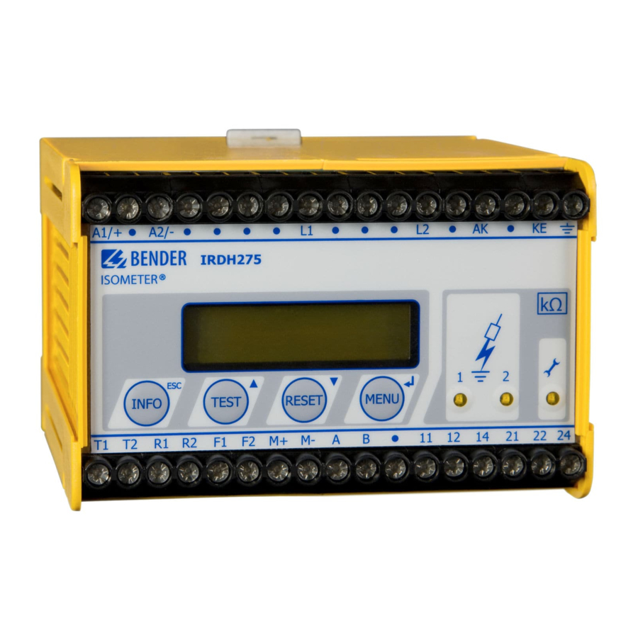
5. Operation and setting 5.1 Operating features and displays IRDH275(B) A-ISOMETER® IRDH275 * * * I T - S Y S T E M * * * * R = 0 8 6 k W INFO TEST RESET MENU 1 INFO key: to query standard information / ESC key: back (menu function), confirmation parameter change 2 TEST button: to call up the self test/ Up key: parameter change, moving up in the menu... -
Page 32: Display In The Standard Mode
Operation and setting 5.1.1 Display in the standard mode I n s u l a t i o n F a u l t R s = 0 1 1 k 1 Indication of the insulation resistance in kΩ 2 Additional information about the insulation resistance: "+"... -
Page 33: Function Keys
Setup status (for details refer to the table of the status numbers on page 68) COM-Setup (IRDH275 bus address) Please have the details above on hand if you have a problem and if you con- tact BENDER for technical questions. Activating the TEST button starts the A-ISOMETER® self test. TEST... - Page 34 Operation and setting For controlling the menu system, the arrow keys, the ENTER key and the ESC key are used: Arrow up key: Moving up in the menu, increasing a parameter TEST Arrow down key: Moving down in the menu, reducing a parameter RESET ENTER key Selecting a menu item or sub menu item, confirming or storing a...
- Page 35 Operation and setting TGH1361en/11.2009...
-
Page 36: Menu Structure And Menu Mode
Operation and setting 5.2 Menu structure and menu mode Switchover to the menu mode After pressing the MENU key, you can change from the standard mode to the menu mode. From the menu mode you can link to the different sub menus. Navigation within the menu Select the desired menu item using the UP/DOWN keys. -
Page 37: Diagram Menu Structure
Operation and setting 5.2.1 Diagram menu structure *** IT-SYSTEM *** MENU R >010 MW 1. EXIT 2. HISTORY INFO 3. ISO SETUP 4. ISO ADVANCED 5. COM SETUP 6. PASSWORD 7. LANGUAGE 8. SERVICE HISTORY INFO ISO SETUP ISO ADVANCED COM SETUP PASSWORD LANGUAGE... -
Page 38: Menu History Info (Irdh275B)
Operation and setting 5.3 Menu HISTORY INFO (IRDH275B) 99 events with date and time stamp can be stored in the memory database. The database is designed as a ring memory, i.e. the eldest entry is overwrit- ten. Data is written into a non-volatile memory and therefore provides pro- tection against voltage failure. -
Page 39: Diagram History Info (Irdh275B)
Operation and setting 5.3.1 Diagram HISTORY INFO (IRDH275B) *** IT-SYSTEM *** R >010 MW 1. EXIT 2. HISTORY INFO 3. ISO SETUP 4. ISO ADVANCED 5. COM SETUP 6. PASSWORD 7. LANGUAGE 8. SERVICE Nr.: 01 #Nr: 08 Power on Nr.: 01 #Nr: 08 Clear all: off Nr.: 01 #Nr: 08... -
Page 40: Menu Iso Setup: Setting Of The Basic A-Isometer® Functions
Operation and setting 5.4 Menu ISO SETUP: Setting of the basic A-ISOMETER® functions All alarm functions such as Alarm 1 and Alarm 2 (prewarning and main alarm), the operating principle of the alarm relays K1 and K2 (N.O = N/O operation, N.C = N/C operation), the fault storage behaviour and a selection of two current output ranges are set in this menu. - Page 41 Operation and setting Diagram ISO SETUP *** IT-SYSTEM *** R >010 MW 1. EXIT 2. HISTORY INFO 3. ISO SETUP 4. ISO ADVANCED 5. COM SETUP 6. PASSWORD 7. LANGUAGE 8. SERVICE 1. Exit 2. Alarm1: 100 KW Alarm1 : 100 KW 3.
-
Page 42: Memory Setting (On/Off)
Operation and setting During the automatic self test, the alarm relays are not switched over. When a device fault occurs at the A-ISOMETER®, the relay K2 will au- tomatically be activated as a device fault relay. 5.4.3 Memory setting (on/off) Memory: on = Fault memory is activated The device must be reset with the RESET button after... -
Page 43: Menu Iso Advanced: Setting Of The Extended Functions
Operation and setting 5.5 Menu ISO ADVANCED: Setting of the extended functions 5.5.1 External coupling devices (AGH: no) Basic setting "no", when no coupling device is used (factory setting). AGH: 204 AK80 Terminal AK of the IRDH275 is connected to terminal AK80 of the AGH204S-4. -
Page 44: Adaptation To The System Leakage Capacitance (Cemax : 150 Μf)
Operation and setting 5.5.2 Adaptation to the system leakage capacitance (Cemax: 150 µ This menu allows to adapt the A-ISOMETER® to the maximum system leak- age capacitance (max. 500 µF). Please note that the basic measuring time will be increased to approximately 10 seconds when the setting is C = 500 µF. -
Page 45: Diagram Iso Advanced
Operation and setting 5.5.8 Diagram ISO ADVANCED *** IT-SYSTEM *** R >010 MW 1. EXIT 2. HISTORY INFO 3. ISO SETUP 4. ISO ADVANCED 5. COM SETUP 6. PASSWORD 7. LANGUAGE 8. SERVICE 150 AK160 204 AK160 520S 204 AK80 1. -
Page 46: Menu Com Setup: Setting The Bms Interface
Operation and setting 5.6 Menu COM SETUP: Setting the BMS interface 5.6.1 Bus address „Addr:“ (IRDH275B) This menu item is used to set the BMS bus address of the IRDH275. Since there are several A-ISOMETERs in one system, take care that the bus address is not assigned twice. -
Page 47: Diagram Com Setup (Irdh275B)
Operation and setting 5.6.4 Diagram COM SETUP (IRDH275B) *** IT-SYSTEM *** R >010 MW 1. EXIT 2. HISTORY INFO 3. ISO SETUP 4. ISO ADVANCED 5. COM SETUP 6. PASSWORD 7. LANGUAGE 8. SERVICE 1. Exit 2. Addr: 003 Addr : 003 3. -
Page 48: Menu Password
Operation and setting 5.7 Menu PASSWORD 5.7.1 Activating and setting the password This menu can be used to activate a "Password" query. This protects the A- ISOMETER® against unauthorized settings and modifications. The desired password (menu item 2. Password: xxx) can be set with the UP/DOWN keys and confirmed with the ENTER key. -
Page 49: Menu Language
Operation and setting 5.8 Menu LANGUAGE 5.8.1 Setting the national language The menu item "Language" allows fault messages of the A-ISOMETER® to be set to different languages. There is the choice of German and English. The device menu is not influenced by the language selection. 5.8.2 Diagram Language *** IT-SYSTEM *** R >010 M... -
Page 50: Menu Service
Operation and setting 5.9 Menu SERVICE This menu item is provided for the BENDER service personnel and is pro- tected by a password against erroneous settings. It is intended to provide fast fault clearance by qualified experts in the event of a device error. -
Page 51: Serial Interfaces
6. Serial interfaces The A-ISOMETERs® IRDH275 and IRDH275B have differently designed se- rial interfaces. -RS485 and IsoData protocol IRDH275 -galvanically isolated -ASCII, unidirectional -RS485 and BMS protocol IRDH275B -galvanically isolated -ASCII, bidirectional 6.1 RS485 interface with IsoData protocol (IRDH275) Data transmission is continuously carried out and can neither be interrupted by the data slave station nor be influenced in any other way. - Page 52 Serial interfaces Start US= Unit separator Response value Measuring value Alarm1 e.g. 60 kW e.g. 128 kW = No alarm Response value = Alarm1 Alarm2 e.g. 120 kW = Alarm2 = Alarm1/2 = K1 off, K2 off = AC fault = K1 on, K2 off = DC- fault = K1 off, K2 on...
-
Page 53: Rs485 Interface With Bms Protocol (Irdh275B)
Serial interfaces 6.2 RS485 interface with BMS protocol (IRDH275B) The RS485 interface galvanically isolated from the device electronics and cur- rent output serves as a physical transmission medium for the BMS protocol. If several IRDH275B or other bus-capable devices are interconnected in a network via the BMS bus, the BMS bus must be terminated at both ends with a 120 Ω... -
Page 54: Topology Rs485 Network (Irdh275B)
(e.g. J-Y(St)Y 2 x 0.6), screen on one side connected to earth (PE). Connection to the terminals A and B. The number of bus nodes is restricted to 32 devices. When more devices are to be connected, Bender recommends to use an RS485 repeater DI1. TGH1361en/11.2009... -
Page 55: Bms Protocol (Irdh275B)
Serial interfaces 6.4 BMS protocol (IRDH275B) This protocol is an essential part of the Bender Measuring Device Interface. Data transmission generally makes use of ASCII characters. Interface data are: Baud rate:9600 baud transmission:1 start bit, 7 data bits, 1 parity bit, 1 stop bit (1, 7, E, 1) -
Page 56: Bms Slave
Serial interfaces 6.4.2 BMS Slave All IRDH275B are factory set to slave mode (address 3). In a BMS network, one address must be selected from the address range 2...30 for each slave. There may be no gaps of more than five subsequent addresses, so that all slaves can be scanned by the Master. -
Page 57: Commissioning Of An Rs485 Network With Bms Protocol
Serial interfaces The following table gives an overview about essential alarm messages and the assignment of the messages indicated on the display or operator panels, e.g. PRC1470. Message Meaning Channel Insulation Fault Insulation resistance < setting Alarm 1 Insulation Fault Insulation resistance <... - Page 58 Serial interfaces BMS-bus address ranges Addresses* Device Meaning There is no device with address 0 ! Information sent to address 0 applies to all devices connected to the interface (broadcast) 1 PRC1470 Control and indicating device IRDH275B/ 1...30 Insulation monitoring device 375B/575 1...30 FTC470...
-
Page 59: Technical Data Irdh275(B)
7. Technical data IRDH275(B) 7.1 Data in tabular form The values marked with * are absolute values Insulation coordination acc. to IEC 60664-1 Rated voltage ..........................AC 800 V Rated impulse voltage/pollution degree..................8 kV / 3 Voltage ranges IRDH275..: Nominal voltage range U ................1AC / 3 (N) AC 0...793 V* Nominal frequency f (for f<50 Hz see characteristic curve on page 64) ...... - Page 60 Technical data IRDH275(B) ................≤ DC 1200 V Permissible extraneous DC voltage U ................≤ 500 μF Permissible system leakage capacitance C Factory setting ..........................150 μF Displays Display, illuminated......................two-line display Characters (number of characters) ....................2 x 16 Ω...
-
Page 61: General Data
Technical data IRDH275(B) General data EMC immunity ......................... acc. to EN 61326 EMC emission ........................acc. to EN 61326 Shock resistance IEC 60068-2-27 (device in operation) ............15 g / 11 ms Bumping IEC 60068-2-29 (during transport)................. 40 g / 6 ms Vibration resistance IEC 60068-2-6 (device in operation)..........1 g / 10...150 Hz Vibration resistance IEC 60068-2-6 (during transport) ..........2 g / 10...150 Hz Ambient temperature (during operation) ................-10 °C...+55 °C... -
Page 62: Standards And Approvals
Technical data IRDH275(B) 7.2 Standards and approvals The A-ISOMETER® was designed under consideration of the following standards: - DIN EN 61557-8 (VDE 0413-8):1998-05 - EN 61557-8:1997-03 - IEC 61557-8:1997-02 - EN 61326 - DIN EN 60664-1 (VDE 0110-1):2003-11 - DIN EN 60664-3 (VDE 0110-3):2003-09 - ASTM F1669M-96(2002) - ASTM F1207M-96(2002) TGH1361en/11.2009... -
Page 63: Characteristic Curves
Technical data IRDH275(B) 7.3 Characteristic curves A-ISOMETER® response times in relation to system leakage capacitances of: = 1...500 µF, U = 0...793 V / 50 Hz 1000 ≤ Ω 10 M ≥ Ω 1000 [μF] TGH1361en/11.2009... - Page 64 Technical data IRDH275(B) Max. AC voltage between the IT system and earth in the frequency range <50 Hz 10000 AGH520S AGH204S-4 1000 IRDH275 [Hz] TGH1361en/11.2009...
- Page 65 Technical data IRDH275(B) Current output 0...400 μA (only IRDH275) [ kW] [ mA] 400 mA x 120 kW - 120 kW = Insulation fault in kΩ I = Current output in mA TGH1361en/11.2009...
- Page 66 Technical data IRDH275(B) Current output 0...20 mA (IRDH275B) [kW] 10 000 1000 I [mA] 20 mA x 120 kW - 120 kW = Insulation fault in kΩ = Current output in mA TGH1361en/11.2009...
- Page 67 Technical data IRDH275(B) Current output 4...20 mA (IRDH275B) [kW] 10 000 1000 I [mA] 16 mA x 120 kW - 120 kW I - 4 mA = Insulation fault in kΩ = Current output in mA TGH1361en/11.2009...
- Page 68 Technical data IRDH275(B) Status number TGH1361en/11.2009...
- Page 69 Technical data IRDH275(B) Dimension diagram enclosure IRDH275(B) ø 4,5 mm DIN rail mounting according to IEC 60715 Screw mounting by means of a plug-in trapezoidal support Order No.: 990056 (Option W) TGH1361en/11.2009...
-
Page 70: Ordering Details
Technical data IRDH275(B) 7.4 Ordering details 7.4.1 A-ISOMETER® Nominal voltage Supply voltage Type Art.-No. 3(N)AC 0...793 V AC 88...264 V IRDH275-435 B 9106 5100 DC 0...650 V DC 77...286 V IRDH275W-435 „ „ B 9106 5100W IRDH275B-435 „ „ B 9106 5101 IRDH275BW-435 „... -
Page 71: Coupling Devices
Technical data IRDH275(B) 7.4.2 Coupling devices Nominal voltage Art. No. Type range U AGH204S-4 AC 0...1650 V B 914 013 AGH520S AC 0...7200 V B 913 033 AGH150W-4 DC 0...1760 V B 9801 8006 7.4.3 Measuring instruments Type Measuring range Dimensions Art. - Page 72 Technical data IRDH275(B) TGH1361en/11.2009...
- Page 73 Alarm messages Display in the menu mode Approvals Display in the standard mode Automatic self test Explanations of symbols and warnings Bender Measuring Device Interface External coupling devices BMS bus External RESET button - correct arrangement External TEST button - wrong arrangement...
- Page 74 INDEX Setting the response values Alarm 1 and Alarm 2 Measuring instruments Setting the system leakage capacitance Memory database Standards Menu Status number - COM SETUP - HISTORY INFO - ISO ADVANCED - ISO SETUP Technical data IRDH275 - LANGUAGE Terminating resistor - PASSWORD TEST button...
- Page 76 Dipl.-Ing. W. Bender GmbH & Co. KG Londorfer Str. 65 • 35305 Grünberg • Germany Postfach 1161 • 35301 Grünberg • Germany Tel.: +49 6401-807-0 Fax: +49 6401-807-259 E-Mail: info@bender-de.com Web: http://www.bender-de.com...
Need help?
Do you have a question about the A-ISOMETER IRDH275 and is the answer not in the manual?
Questions and answers