Table of Contents
Advertisement
Quick Links
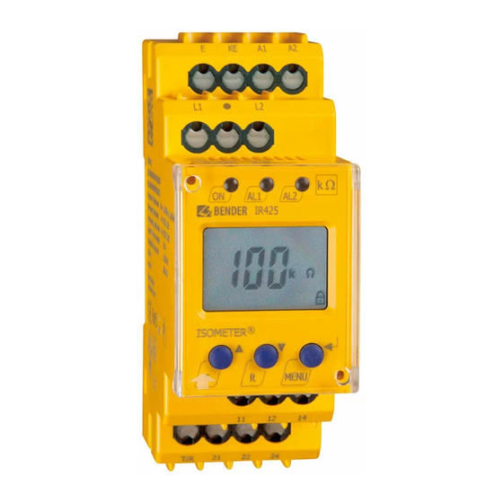
ISOMETER® IR425-D4
Controllore di isolamento
Destinazione d'uso
®
ISOMETER
IR425 controlla la resistenza d'isolamento R
cuito ausiliario AC o DC isolato da terra (sistema IT), rispettiva-
mente a 0...300 V AC o a 0...300 V DC. La capacità di dispersione
massima ammissibile del sistema C
Informazioni generali di sicurezza
Oltre alla presente scheda tecnica, la documentazione dell'appa-
recchio include anche un documento contenente istruzioni im-
portanti sulla sicurezza per i prodotti Bender.
Informazioni di sicurezza specifiche per l'apparecchio
In ciascun sistema interconnesso è possibile collegare
un solo controllore d'isolamento.
Prima di eseguire i test d'isolamento e di tensione, il
controllore d'isolamento deve essere disconnesso dal
sistema IT per la durata delle prove.
Funzionamento
®
Il controllore ISOMETER
IR425 genera una tensione di misura
pulsante, che viene applicata al sistema IT da sorvegliare tramite
i morsetti L1/L2 e KE/E. Un eventuale guasto d'isolamento ohmi-
co tra sistema IT e terra chiude il circuito di misura. La resistenza
d'isolamento attuale misurata viene visualizzata sul display
dell'apparecchio.
Funzione Preset
Dopo avere collegato per la prima volta la tensione di alimenta-
zione U
e il sistema IT, i valori di soglia R
S
gono automaticamente impostati sui seguenti valori:
U
> 72 V: valore di soglia 1 = 46 kΩ, valore di soglia 2 = 23 kΩ
n
≤
U
72 V: valore di soglia 1 = 20 kΩ, valore di soglia 2 = 10 kΩ
n
La funzione Preset viene nuovamente eseguita in seguito al ripri-
stino dell'apparecchio alle impostazioni di fabbrica.
Test automatico
Dopo il collegamento della tensione di alimentazione U
recchio esegue una verifica interna, che viene quindi ripetuta
ogni 24 ore. Durante questa verifica vengono rilevati gli eventuali
guasti funzionali o di collegamento e visualizzati sotto forma di
codice di errore sul display. I relè di uscita non vengono control-
lati durante questo test.
Test manuale
Premendo il pulsante Test interno/esterno per > 1,5 s, l'apparec-
chio esegue una verifica durante la quale vengono rilevati gli
eventuali guasti funzionali o di collegamento e visualizzati sotto
forma di codice di errore sul display. I relè di uscita vengono con-
trollati durante questo test.
Mantenendo premuto il pulsante Test sul display appaiono tutti i
segni grafici utilizzati dal'apparecchio.
Malfunzionamento
In caso di malfunzionamento, il relè K2 (21, 22, 24) commuta e tut-
ti e tre i LED lampeggiano. Il display mostra un codice di errore.
E01 =
errore di collegamento conduttore di protezione (PE),
nessun collegamento a bassa resistenza tra E e KE.
E02 =
errore di collegamento alla rete controllata,
nessun collegamento a bassa resistenza tra L1 e L2.
E03...Exx
= errore interno dell'apparecchio
IR425-D4_D00039_00_M_ITEN / 07.2013
Italiano
di un cir-
F
max è pari a 20 μF.
e
/R
(Alarm 1/2) ven-
an1
an2
l'appa-
S
Insulation monitoring device
Intended use
®
The IR425 ISOMETER
monitors the insulation resistance of an un-
earthed AC or DC control circuit (IT system) of AC 0...300 V respec-
tively DC 0...300 V. The maximum permissible system leakage
capacitance C
is 20 μF.
e
Safety instructions
In addition to this data sheet, the documentation of the device in-
cludes a sheet entitled "Important safety instructions for Bender
products".
Device-specific safety information
Only one insulation monitoring device may be used
in each interconnected system.
When insulation and voltage tests are to be carried
out, the device shall be isolated from the system for
the test period.
Function
®
The IR425 ISOMETER
generates a pulsating measuring voltage
which is superimposed on the IT system being monitored via the
terminals L1/L2 and KE/earth. Ohmic insulation faults close the
measuring circuit between the IT system and earth. The currently
measured insulation resistance is shown on the display of the de-
vice.
Preset function
After connecting the supply voltage U
tem for the first time, the response values R
are automatically set once to:
U
> 72 V: response value 1 = 46 kΩ, response value 2 = 23 kΩ
n
≤
U
72 V: response value 1 = 20 kΩ, response value 2 = 10 kΩ
n
After resetting the device values to its factory settings, the Preset
function is automatically active again.
Automatic self test
The device automatically carries out a self test after connecting to
the supply voltage U
and later every 24 hours. During the self
S
test, internal functional faults or connection faults will be deter-
mined and will appear in form of an error code on the display. The
alarm relays are not checked during this test.
Manual self test
After pressing the internal/external test button for > 1.5 s, the de-
vice carries out a self test. During this test, internal functional
faults, or connection faults will be determined and will appear in
form of an error code on the display. The alarm relays are checked
during this test.
With the test button pressed and held down, all device-related
display elements appear on the display.
Malfunction
In case of a malfunction, the relay K2 (21, 22, 24) switches and all
of the three LEDs flash. An error code appears on the display.
E01 =
PE connection fault, no low-resistance
connection between E and KE.
E02 =
system connection fault,
no low-resistance connection between L1 and L2.
E03...Exx
= internal device error
English
and connecting the IT sys-
S
/R
(Alarm 1/2)
an1
an2
1
Advertisement
Table of Contents

Related Manuals for Bender ISOMETER IR425-D4


Summary of Contents for Bender ISOMETER IR425-D4
- Page 1 Oltre alla presente scheda tecnica, la documentazione dell'appa- In addition to this data sheet, the documentation of the device in- recchio include anche un documento contenente istruzioni im- cludes a sheet entitled "Important safety instructions for Bender portanti sulla sicurezza per i prodotti Bender. products".
- Page 2 ISOMETER® IR425-D4 Temporizzazioni t e t Time delays t and t I tempi t e t descritti nel seguito determinano dei ritardi nelle segna- The times t and t described below delay the indication of lazioni degli allarmi tramite LED e relè. alarms via LEDs and relays.
- Page 3 ISOMETER® IR425-D4 Schema di collegamento Wiring diagram MENU ~/– TEST RESET IT-System Morsetto Collegamento Terminal Connection E, KE Collegare separatamente E e KE al conduttore di E, KE Connect the leads E and KE separately to PE protezione (PE) A1, A2 Tensione di alimentazione U (v.
- Page 4 ISOMETER® IR425-D4 Ele- Pannello frontale/ Ele- Funzione Function mento Front of the device ment LED di funzionamento, verde Power ON LED, green LED allarme 1 acceso (giallo): valore LED Alarm 1 lights ( yellow): AL1, rilevato minore del valore di soglia 1 AL1, value below response value 1 LED allarme 2 acceso (giallo): valore...
- Page 5 ISOMETER® IR425-D4 Impostazione dei parametri Parameter settings Di seguito viene fornito un esempio di come modificare il valore An example is given below on how to change the alarm response di soglia dell'allarme R (R 2). Procedere come segue: value R (R 2).
- Page 6 ISOMETER® IR425-D4 Regolazione delle temporizzazioni Setting the time delay Questa voce di menù permette di impostare un ritardo d'inter- Use this segment to enter the response delay t (0...99 s) and the vento t (0...99 s) ed un ritardo iniziale t (0...10 s). starting delay t (0...10 s).
- Page 7 ISOMETER® IR425-D4 Dati tecnici IR425-D4.. Technical data IR425-D4.. Coordinamento dell'isolamento sec. IEC 60664-1/IEC 60664-3 Insulation coordination acc. to IEC 60664-1/IEC 60664-3 Tensione nominale d'isolamento ................... 250 V Rated insulation voltage......................250 V Tensione nominale di tenuta all'impulso / grado di inquinamento ........4 kV / 3 Rated impulse voltage / Pollution degree................
- Page 8 Soggetto a modifiche! Subject to change! © © Bender GmbH & Co. KG Bender GmbH & Co. KG Bender GmbH & Co. KG Tel.: +49 6401 807-0 E-Mail: info@bender-de.com •...
Need help?
Do you have a question about the ISOMETER IR425-D4 and is the answer not in the manual?
Questions and answers