Table of Contents
Advertisement
Quick Links
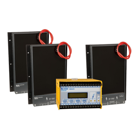
ISOMETER® IRDH275BM-7
Coupling device AGH675S-7
and AGH675S-7MV15
Insulation monitoring device for medium voltage IT systems with galva-
nically connected rectifiers and converters up to AC/DC 15.5 kV in com-
bination with the coupling devices AGH675S-7 and AGH675S-7MV15
IRDH275BM-7_D00123_07_M_XXEN / 08/2020
Manual EN
Advertisement
Table of Contents

Subscribe to Our Youtube Channel
Related Manuals for Bender ISOMETER IRDH275BM-7


Summary of Contents for Bender ISOMETER IRDH275BM-7
- Page 1 ISOMETER® IRDH275BM-7 Coupling device AGH675S-7 and AGH675S-7MV15 Insulation monitoring device for medium voltage IT systems with galva- nically connected rectifiers and converters up to AC/DC 15.5 kV in com- bination with the coupling devices AGH675S-7 and AGH675S-7MV15 IRDH275BM-7_D00123_07_M_XXEN / 08/2020 Manual EN...
- Page 2 Service and support for Bender products First-level support Technical support Carl-Benz-Strasse 8 • 35305 Grünberg • Germany Telephone: +49 6401 807-760 0700BenderHelp * Fax: +49 6401 807-629 E-mail: support@bender-service.de Available on 365 days from 7.00 a.m. to 8.00 p.m. (MEZ/UTC +1) * Landline German Telekom: Mon-Fri from 9.00 a.m.
-
Page 3: Table Of Contents
1.2.1 Signs and symbols ......................5 Training courses and seminars.................5 Delivery conditions .......................5 Inspection, transport and storage ................5 Warranty and liability....................6 Disposal of Bender devices ..................6 Safety ..........................6 Device-specific safety information .................6 1.10 Intended use ........................7 1.11 Directions for installation ...................7 Function ....................9... - Page 4 4.5.1 Coupling devices AGH: 675S-7… ................. 23 4.5.2 Adaptation to the system leakage capacitance C max ....... 23 4.5.3 Measuring principle (Measure: AMP) ..............23 4.5.4 Setting the repetition time for automatic self tests (Autotest: 24h) ..23 4.5.5 Setting the real-time clock (Clock) ............... 23 4.5.6 Setting the date (Date) .....................
-
Page 5: General Instructions
Training courses and seminars www.bender.de > Know-how-> Seminars. Delivery conditions The conditions of sale and delivery set out by Bender apply. These can be obtained from Bender in printed or electronic format. The following applies to software products: “Software clause in respect of the licensing of standard software as part of de-... -
Page 6: Warranty And Liability
• Non-observance of technical data. • Repairs carried out incorrectly. • Use of accessories and spare parts not recommended by Bender. • Catastrophes caused by external influences and force majeure. • Mounting and installation with device combinations not recommended by the manufacturer. -
Page 7: Intended Use
ISOMETER® IRDH275BM-7 In the event of an alarm message of the ISOMETER®, the insulation fault should be eliminated as qui- ckly as possible. If the device is installed inside a control cabinet, the insulation fault message must be audible and/or visible to attract attention. When using ISOMETER®s in IT systems, make sure that only one active ISOMETER®... - Page 8 General instructions Factory setting device variant -7... ISO SETUP: Alarm 1 / Alarm 2 = 2 MΩ/ 100 kΩ (response value) ISO SETUP: Operating principle K1/K2 = N/O operation ISO SETUP: Memory = off ISO ADVANCED: System leakage capacitance = 2 μF ISO ADVANCED: Coupling device = AGH: 675S-7...
-
Page 9: Function
• Automatic device self test • Memory with real-time clock to store all alarm messages with date and time stamp. • BMS interface (BMS protocol) for data exchange with other Bender devices (RS-485 electrically isolated). • Current output 0 (4)…20mA (galvanically separated) in relation to the measured insulation value. -
Page 10: Function Description
(adaptive measuring pulse) a measuring principle developed by Bender (European Patent: EP 0 654 673 B1). Self test A self test can be carried out manually using the TEST button or automatically. In order to guarantee high functional reliability, the ISOMETER®... - Page 11 1. Press TEST button 2. Switch the supply voltage off and on 3. Contact Bender If the on/off switching of the supply voltage is not possible for technical reasons, a RESET of the pro- cess control can be carried out by pressing the „ESC“, „RESET“ and „MENU“ key.
-
Page 12: Dimensions, Installation And Connection
Dimensions, installation and connection Dimensions, installation and connection Dimension diagrams > 146 > 78 R > 64 ø 8 AGH675S-7… ø M4 Dimension diagram IRDH275, all dimensions in mm Dimension diagram AGH675S-7, all dimensions in mm Mounting IRDH275 DIN rail mounting according to DIN EN 60715/IEC 60715 or Screw mounting by means of a plug-in trapezoidal support (Order No.: 990056) Installation of the coupling device AGH675S-7…... -
Page 13: Wiring Diagrams (By Way Of Example)
ISOMETER® IRDH275BM-7 Wiring diagrams (by way of example) Wiring AGH675S-7 IRDH275BM-7_D00123_07_M_XXEN / 08/2020... - Page 14 Dimensions, installation and connection Wiring AGH675S-7MV15 DC 15,5 kV 15,5 kV AC/DC 15,5 kV AC/DC AGH675S-7MV15 AGH675S-7MV15 Legend wiring diagrams Supply voltage U (see nameplate) via 6 A fuse 2, 3 Terminals L1, L2 are not connected! Connection to the coupling device AGH675S-7 or the two coupling devices AGH675S-7MV15: connect terminal AK to terminal(s) 5 of the coupling device AGH675S-7 (or the two coupling devices AGH675S-7MV15), connection with standard low-voltage cable, maximum voltage at terminal 5: 200 V Separate connection of...
- Page 15 ISOMETER® IRDH275BM-7 Serial interface RS-485 (termination 120 Ω resistor) Alarm relay 1; changeover contacts provided Alarm relay 2 (system fault relay); changeover contacts provided Connection of the coupling device AGH675S-7 to the converter: connect the high voltage cable encapsulated on one end to the mid-point of the DC intermediate circuit.
-
Page 16: Operation And Setting
Operation and setting Operation and setting Operating features and displays IRDH275BM-7 IRDH275 ISOMETER® INFO key: to query standard information / ESC key: back to the menu function, confirmation parameter change TEST button: to call up the self test/ Up key: parameter change, moving up in the menu RESET button: to delete insulation fault alarms Down key: parameter change, moving down in the menu MENU key: to activate the menu system / Enter key: confirmation parameter change... -
Page 17: Display In The Menu Mode
• COM-Setup (own bus address) Please have the details above on hand if you have a problem and if you contact Bender for technical questions.. Starts the ISOMETER® self test. Moving up in the menu, increasing a parameter... -
Page 18: Menu Structure And Menu Mode
Operation and setting Menu structure and menu mode ENTER In the following menu diagrams these symbols are used for the UP/DOWN sake of clarity: ESCAPE Switchover to the menu mode After pressing the MENU key, you can change from the standard mode to the menu mode. From the menu mode you can link to the different sub menus. -
Page 19: Diagram Menu Structure
ISOMETER® IRDH275BM-7 4.2.1 Diagram menu structure Menu HISTORY INFO 99 events with date and time stamp can be stored in the memory database. The database is designed as a ring memory, i.e. the eldest entry is overwritten. Data is written into a non-volatile memory and therefore provides protection against voltage failure. -
Page 20: Diagram History Info
Operation and setting 3...99 Device error released Device error 3...99 Device error cleared Device error 3...99 System reset (watchdog) System reset Before storing the events with the actual date and time stamp, set the realtime clock in the ADVANCED menu. The following function keys are provided to query data from the „HISTORY INFO“... -
Page 21: Menu Iso Setup: Setting Of The Basic Isometer® Functions
ISOMETER® IRDH275BM-7 Menu ISO SETUP: Setting of the basic ISOMETER® functions All alarm functions such as Alarm 1 and Alarm 2 (prewarning and main alarm), the operating principle of the alarm relays K1 and K2 (N.O = N/O operation, N.C = N/C operation), the fault storage behaviour and a selection of two current output ranges are set in this menu. -
Page 22: Diagram Iso Setup
Operation and setting 4.4.3 Diagram ISO SETUP During the automatic self test, the alarm relays are not switched over. When a system fault occurs at the ISOMETER®, the relay K2 will automatically be activated as a sys- tem fault relay. 4.4.4 Memory settings (on/off) Memory: on Fault memory is activated... -
Page 23: Current Output For External Measuring Instruments
ISOMETER® IRDH275BM-7 4.4.5 Current output for external measuring instruments Factory setting: 0…20 mA The current output of the IRDH275BM-7 can be set to „0…20 mA“ or „4…20 mA“ via the menu point „M+/M-:“. The maximum load is 500 Ω. Function 0…20 mA: = 20 mA x 2800 kΩ... -
Page 24: Setting The Date (Date)
Operation and setting 4.5.6 Setting the date (Date) As well as the time, the date is required for the memory, too. In the event of power supply failure, the date function is not influenced for at least 30 days. If the device is switched on again after this period, a new setting of date and time of the real-time clock is required. -
Page 25: Menu Com Setup: Setting The Bms Interface
ISOMETER® IRDH275BM-7 Menu COM SETUP: Setting the BMS interface 4.6.1 Bus address „Addr:“ This menu item is used to set the BMS bus address of the ISOMETER®. Since there are several ISOMETERs in one system, take care that the bus address is not assigned twice. The device is factory set to address 3 and hence acts as a slave. -
Page 26: Menu Password
Operation and setting Menu PASSWORD 4.7.1 Activating and setting the password This menu can be used to activate a „Password“ query. This protects the ISOMETER® against unauthori- zed settings and modifications. The desired password (menu item 2. Password: xxx) can be set with the UP/DOWN keys and confirmed with the ENTER key. -
Page 27: Diagram Language
4.8.2 Diagram Language Menu SERVICE This menu item is provided for the Bender service personnel and is protected by a password against er- roneous settings. It is intended to provide fast fault clearance by qualified experts in the event of a device error. -
Page 28: Serial Interfaces
Serial interfaces Serial interfaces RS-485 interface with BMS protocol The RS-485 interface which is galvanically isolated from the device electronics and current output ser- ves as a physical transmission medium for the BMS protocol. If several ISOMETER®s or other bus-capa- ble devices are interconnected in a network via the BMS bus, the BMS bus must be terminated at both ends with a 120 resistor. -
Page 29: Wrong Arrangement
0.6 mm (e.g. J-Y(ST)Y 2x0.6), screen on one side connected to earth (PE). Connection to the terminals A and B. The number of bus nodes is restricted to 32 devices. When more devices are to be connected, Bender recommends to use an RS-485 repeater DI1. -
Page 30: Bms Slave
Serial interfaces Faults may be caused when: • addresses are assigned twice • a second master exists on the BMS bus • interference signals occur on the bus lines • a defective device is connected to the bus • terminating resistors are not activated 5.3.2 BMS Slave All IRDH275B are factory set to slave mode (address 3). -
Page 31: Commissioning Of An Rs-485 Network With Bms Protocol
ISOMETER® IRDH275BM-7 5.3.3 Commissioning of an RS-485 network with BMS protocol • Connect the terminals A and B of all bus nodes in one line • Switch the terminating resistors on at the beginning and end of the RS-485 network or in case of devices without a terminating switch, at the end of the bus, connect a 120 resistor to the terminals A and B. -
Page 32: Technical Data Irdh275Bm-7 With Agh675S-7
Technical data IRDH275BM-7 with AGH675S-7… Technical data IRDH275BM-7 with AGH675S-7… Data in tabular IRDH275BM-7 Insulation coordination acc. to IEC 60664-1 Rated voltage ....................................AC 800 V Rated impulse voltage/pollution degree ............................8 kV/3 Voltage ranges Nominal voltage range U ............................via AGH675S-7… Supply voltage U (refer to nameplate for other values) .................... - Page 33 ISOMETER® IRDH275BM-7 Switching components Switching components ................. 2 changeover contacts: K1 (Alarm 1), K2 (Alarm 2, system fault) Operating principle K1, K2 (Alarm 1, Alarm 2) ......................N/O or N/C operation Factory setting (Alarm 1/Alarm 2) ............................N/O operation Electrical endurance ............................12,000 switching operations Contact class.
-
Page 34: Data In Tabular Agh675S-7
Technical data IRDH275BM-7 with AGH675S-7… Data in tabular AGH675S-7 Insulation coordination in consideration of IEC 61800-5-1:2003 Rated voltage ....................................AC 7.2 V Voltage test in consideration of IEC 61800-5-1:2003 All voltage tests were performed with a minimum device distance; see „Chapter Mounting the coupling device AGH675S-7...“. Type test: Rated impulse voltage (basic insulation) ............................40 kV AC voltage test (basic insulation). -
Page 35: Data In Tabular Agh675S-7Mv15
ISOMETER® IRDH275BM-7 Data in tabular AGH675S-7MV15 Insulation coordination in consideration of IEC 61800-5-1:2003 Rated voltage .................................... AC 15.5 V Voltage test in consideration of IEC 61800-5-1:2003 All voltage tests were performed with a minimum device distance; see „Chapter Mounting the coupling device AGH675S-7...“. Type test: Rated impulse voltage (basic insulation) ............................111 kV AC voltage test (basic insulation). -
Page 36: Characteristic Curves
Technical data IRDH275BM-7 with AGH675S-7… Characteristic curves Current output 0…20 mA (IRDH275BM-7) [kW] 100000 = 20 mA x 2800 kΩ - 2800 kΩ 10000 = Insulation fault in kΩ I = Current output in mA 1000 I [mA] Current output 0…20 mA (IRDH275BM-7 F [kW] 100000 = 16 mA x 2800 kΩ... - Page 37 ISOMETER® IRDH275BM-7 Status number Value of the respective number Position of num- bers from the left K1: N/O operation Test K1: N/C operation Test K1: flashing function K1: N/O operation K1: N/C operation K2: N/O operation Test K2: N/C operation Test K2: flashing function K2: N/O operation K2: N/C operation...
-
Page 38: Standards And Approvals
Technical data IRDH275BM-7 with AGH675S-7… Standards and approvals Standards The ISOMETER® was designed under consideration of the following standard: • IEC 61557-8: 2007 + Corrigendum 2007-05 • IEC 61326: 2002-02 • DIN EN 61557-8: 2007-12 • EN 61557-8: 2007 • EN 61326-2-4: 2006-06 Ed. 1.0 •... - Page 39 ISOMETER® IRDH275BM-7 IRDH275BM-7_D00123_07_M_XXEN / 08/2020...
- Page 40 Nachdruck und Vervielfältigung Reprinting and duplicating nur mit Genehmigung des Herausgebers. only with permission of the publisher. Bender GmbH & Co. KG Bender GmbH & Co. KG Postfach 1161 • 35301 Grünberg • Deutschland PO Box 1161 • 35301 Grünberg • Germany Londorfer Str.
Need help?
Do you have a question about the ISOMETER IRDH275BM-7 and is the answer not in the manual?
Questions and answers